key JEEP CJ 1953 Workshop Manual
[x] Cancel search | Manufacturer: JEEP, Model Year: 1953, Model line: CJ, Model: JEEP CJ 1953Pages: 376, PDF Size: 19.96 MB
Page 338 of 376

Q
WHEELS
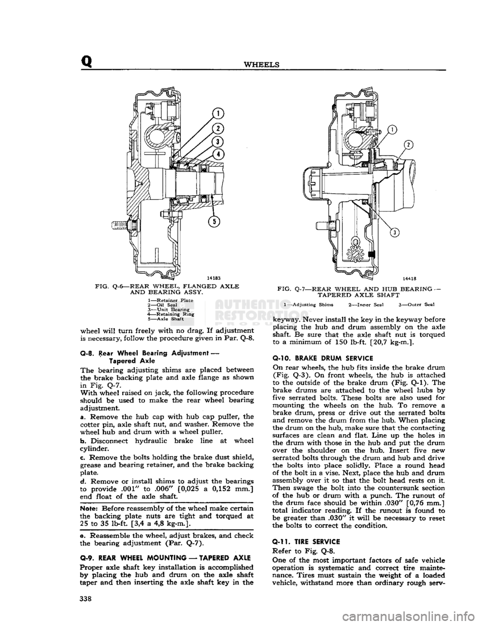
FIG.
Q-6—REAR
WHEEL,
FLANGED
AXLE
AND
BEARING
ASSY.
1—
Retainer
Plate
2— Oil
Seal
3—
Unit
Bearing
4—
Retaining
Ring
5—
Axle
Shaft
wheel
will
turn
freely with no drag. If adjustment
is necessary, follow the procedure given in Par. Q-8.
Q-8.
Rear Wheel Bearing Adjustment
—
Tapered Axle
The
bearing adjusting shims are placed
between
the brake backing plate and axle flange as shown
in
Fig. Q-7.
With
wheel raised on
jack,
the following procedure
should be used to make the
rear
wheel bearing
adjustment.
a.
Remove the hub cap with hub cap puller, the
cotter pin, axle shaft nut, and washer. Remove the
wheel hub and drum with a wheel puller.
b.
Disconnect hydraulic brake line at wheel
cylinder.
c.
Remove the
bolts
holding the brake dust shield, grease and bearing retainer, and the brake backing
plate.
d.
Remove or install shims to adjust the bearings
to provide .001" to .006" [0,025 a 0,152 mm.]
end float of the axle shaft.
Note:
Before reassembly of the wheel make certain
the backing plate nuts are tight and torqued at 25 to 35 lb-ft [3,4 a 4,8 kg-m.].
e. Reassemble the wheel, adjust brakes, and check
the bearing adjustment (Par. Q-7).
0-9.
REAR WHEEL MOUNTING
—
TAPERED AXLE
Proper
axle shaft key installation is accomplished by placing the hub and drum on the axle shaft
taper and then inserting the axle shaft key in the
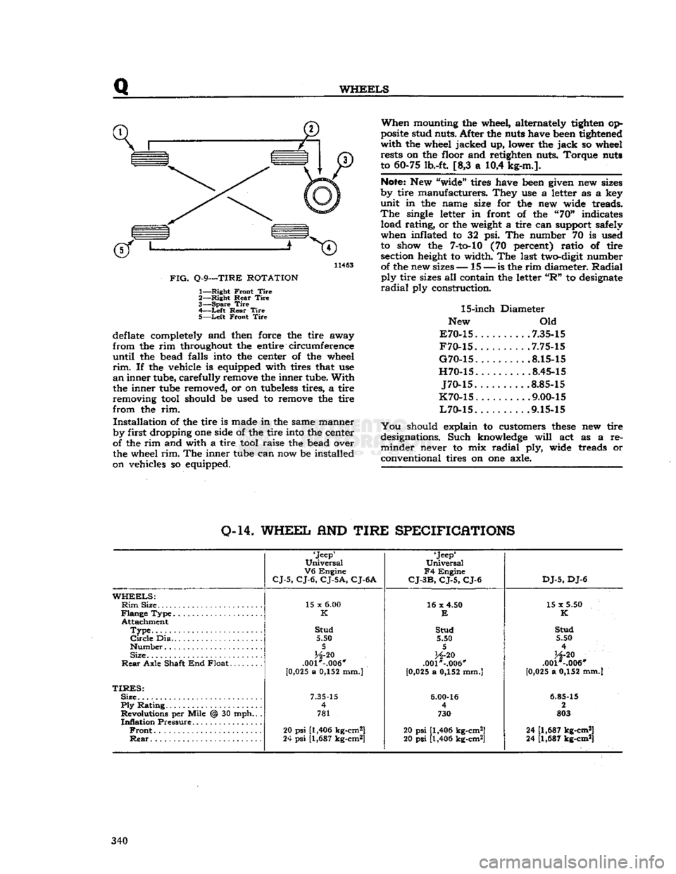
FIG.
Q-7—REAR
WHEEL
AND HUB
BEARING
—
TAPERED
AXLE
SHAFT
1—-Adjusting
Shims
2—Inner
Seal
3—Outer
Seal
keyway.
Never install the key in the keyway before
placing
the hub and drum assembly on the axle
shaft. Be sure that the axle shaft nut is torqued
to a minimum of 150 lb-ft. [20,7 kg-m.].
O-10.
BRAKE
DRUM
SERVICE
On
rear
wheels, the hub fits inside the brake drum
(Fig.
Q-3). On front wheels, the hub is attached
to the outside of the brake drum (Fig. Q-l). The
brake
drums are attached to the wheel hubs by
five serrated bolts. These
bolts
are also used for
mounting the wheels on the hub. To remove a
brake
drum,
press or drive out the serrated
bolts
and
remove the drum from the hub. When placing
the drum on the hub, make sure that the contacting
surfaces are clean and flat.
Line
up the
holes
in
the drum with
those
in the hub and put the drum
over the shoulder on the hub. Insert five new
serrated
bolts
through the drum and hub and drive
the
bolts
into place solidly. Place a round head of the bolt in a vise. Next, place the hub and drum
assembly over it so that the bolt head rests on it.
Then
swage
the bolt into the countersunk section of the hub or drum with a punch. The runout of
the drum face should be within .030" [0,76 mm.]
total indicator reading. If the runout is found to be greater than .030" it
will
be necessary to reset
the
bolts
to correct the condition.
0-11.
TIRE SERVICE
Refer
to Fig. Q-8.
One
of the most important factors of safe vehicle
operation is systematic and correct tire mainte nance.
Tires
must sustain the weight of a loaded vehicle, withstand more than ordinary rough serv- 338
Page 340 of 376

Q
WHEELS
11463
FIG.
Q-9—TIRE
ROTATION
1—
Right
Front
Tire
2—
Right
Rear
Tire
3—
Spare
Tire
4—
-Left
Rear
Tire
5—
Left
Front
Tire
deflate completely and then force the tire away
from
the rim throughout the entire circumference
until
the bead falls into the center of the wheel
rim.
If the vehicle is equipped with tires that use
an
inner tube, carefully remove the inner tube.
With
the inner tube removed, or on tubeless tires, a tire
removing tool should be used to remove the tire
from
the rim.
Installation
of the tire is made in the same manner
by first dropping one side of the tire into the center
of the rim and with a tire tool raise the bead over
the wheel
rim.
The inner tube can now be installed
on vehicles so equipped.
When
mounting the wheel, alternately tighten op
posite stud nuts. After the nuts have been tightened
with
the wheel jacked up, lower the
jack
so wheel rests on the floor and retighten nuts. Torque nuts
to 60-75 lb.-ft. [8,3 a 10,4 kg-m.].
Note:
New "wide" tires have been given new sizes
by tire manufacturers. They use a letter as a key
unit
in the name size for the new wide treads.
The
single letter in front of the "70" indicates load rating, or the weight a tire can support safely
when inflated to 32 psi. The number 70 is used to show the
7-to-10
(70 percent) ratio of tire section height to width. The last two-digit number of the new sizes— 15 —
is
the rim diameter.
Radial
ply
tire sizes all contain the letter
"R"
to designate
radial
ply construction.
15-inch
Diameter
New Old
E70-15
7.35-15
F70-15
.7.75-15
G70-15
8.15-15
H70-15
8.45-15
J70-15
.8.85-15
K70-15
. .... .9.00-15
L70-15
9.15-15
You
should explain to customers
these
new tire
designations. Such knowledge
will
act as a re
minder
never to mix
radial
ply, wide treads or
conventional tires on one axle.
0-14.
WHEEL
AND
TIRE
SPECIFICATIONS
'Jeep'
Universal
V6
Engine
CJ-5,
CJ-6,
CJ-5A,
CJ-6A
'Jeep*
Universal
F4
Engine
CJ-3B,
CJ-5,
CJ-6
DJ-5,
DJ-6
WHEELS:
Rim
Size 15 x
6.00
16 x 4.50
15 x 5.50
K
E
K
Attachment
Type
Stud
Stud Stud
Circle
Dia 5.50 5.50 5.50
5 5
4
Size
H-20
H-20
H-20
Rear
Axle Shaft End Float .001*-.006"
.001"-.006" .001 *-.006"
[0 ,025 a 0,152 mm.)
[0,025 a 0,152 mm.] [0,025 a 0,152 mm.]
TIRES:
Size.
7.35-15
6.00-16
6.85-15
Ply
Rating 4
4 2
Revolutions per Mile @ 30 mph.. . 781 730 803
Inflation
Pressure
Front
20
psi
[1,406 kg-cm2]
20 psi [1,406 kg-cm2] 24 [1,687 kg-cm*]
Rear
24
psi
[1,687 kg-cm*]
20 psi [1,406 kg-cm2] 24 [1,687 kg-cm*] 340