service JEEP CJ 1953 Manual PDF
[x] Cancel search | Manufacturer: JEEP, Model Year: 1953, Model line: CJ, Model: JEEP CJ 1953Pages: 376, PDF Size: 19.96 MB
Page 104 of 376
Dl
DAUNTLESS
V-6
ENGINE
e.
Connect electrical wiring harness to coolant
temperature sending unit. Connect two distributor leads to ignition coil. Connect fuel line
between
fuel pump and carburetor, vacuum
hose
between
distributor and carburetor, and crankcase vent
hose
to intake manifold
below
rear
of carburetor.
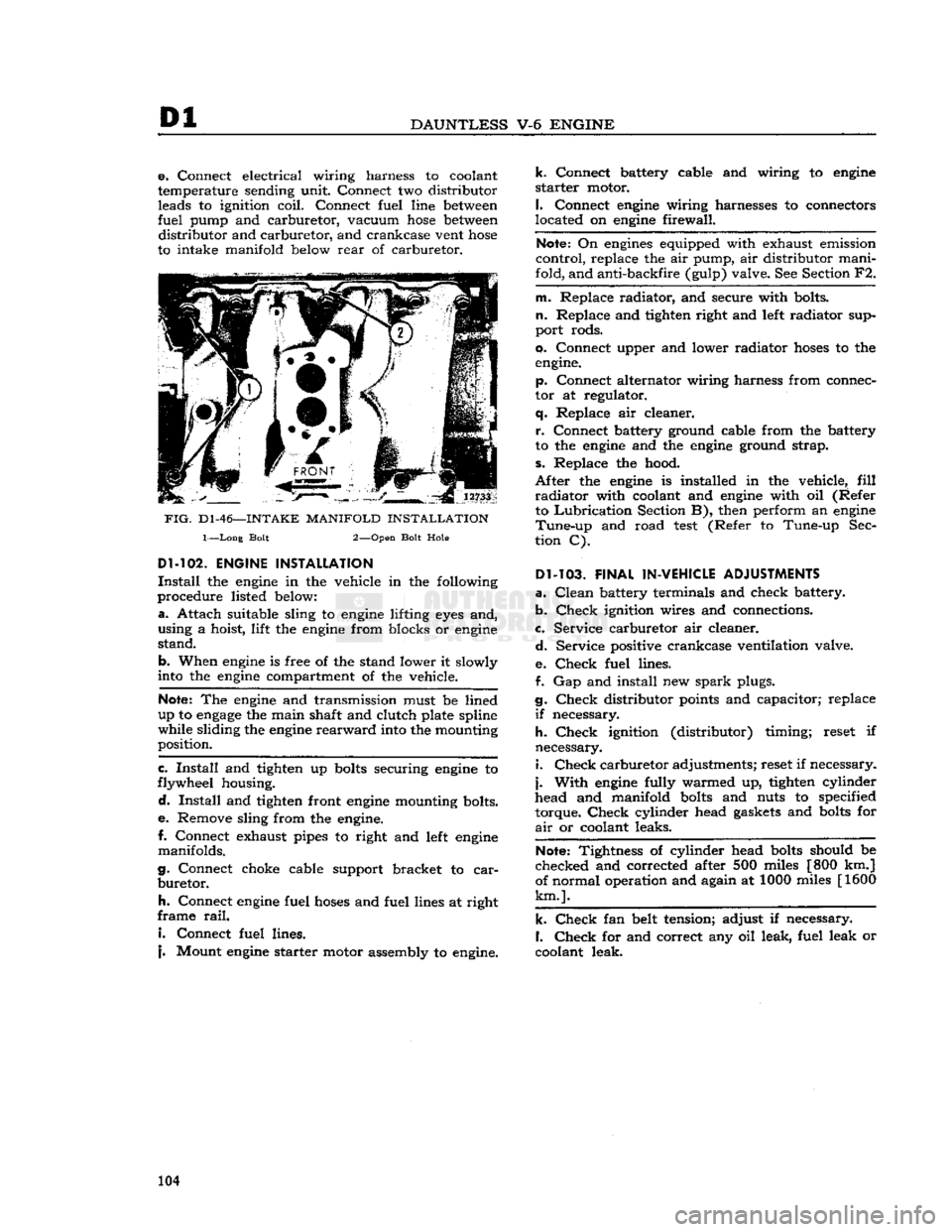
FIG.
D1-46—-INTAKE
MANIFOLD
INSTALLATION
1—Long Bolt 2—Open Bolt Hole
Dl-102.
ENGINE INSTALLATION
Install
the
engine
in the vehicle in the following
procedure listed
below:
a.
Attach suitable sling to
engine
lifting
eyes
and,
using a hoist, lift the
engine
from blocks or
engine
stand.
b. When
engine
is free of the stand lower it slowly
into
the
engine
compartment of the vehicle.
Note:
The
engine
and transmission must be lined
up to
engage
the main shaft and clutch plate spline
while sliding the
engine
rearward
into
the mounting
position.
c.
Install
and tighten up
bolts
securing
engine
to
flywheel housing.
d.
Install
and tighten front
engine
mounting bolts.
e.
Remove sling from the
engine.
I.
Connect exhaust pipes to right and
left
engine
manifolds.
g. Connect choke cable support bracket to
car
buretor.
h.
Connect
engine
fuel
hoses
and fuel lines at right
frame
rail.
I.
Connect fuel lines.
j.
Mount
engine
starter motor assembly to
engine.
k.
Connect battery cable and wiring to
engine
starter
motor.
I.
Connect
engine
wiring harnesses to connectors
located on
engine
firewall.
Note:
On
engines
equipped with exhaust emission
control, replace the air pump, air distributor mani
fold, and anti-backfire (gulp) valve. See Section F2.
m. Replace radiator, and secure with bolts,
n.
Replace and tighten right and
left
radiator sup
port rods.
0. Connect upper and lower radiator
hoses
to the
engine.
p. Connect alternator wiring harness from connec
tor at regulator,
q.
Replace air cleaner.
r.
Connect battery ground cable from the battery
to the
engine
and the
engine
ground strap,
s.
Replace the hood.
After
the
engine
is installed in the vehicle,
fill
radiator
with coolant and
engine
with oil (Refer to
Lubrication
Section B), then perform an
engine
Tune-up
and road
test
(Refer to Tune-up Sec
tion C).
Dl-103.
FINAL IN-VEHICLE ADJUSTMENTS
a.
Clean
battery terminals and check battery.
b.
Check
ignition wires and connections.
c. Service carburetor air cleaner.
d.
Service positive crankcase ventilation valve.
e.
Check
fuel lines.
f. Gap and install new
spark
plugs.
g.
Check
distributor
points
and capacitor; replace
if
necessary.
h.
Check
ignition (distributor) timing; reset if
necessary. 1.
Check
carburetor adjustments; reset if necessary,
j.
With
engine
fully warmed up, tighten cylinder
head and manifold
bolts
and nuts to specified
torque.
Check
cylinder head
gaskets
and
bolts
for
air
or coolant leaks.
Note:
Tightness of cylinder head
bolts
should be
checked and corrected after 500 miles [800 km.]
of normal operation and again at 1000 miles [1600
km.].
k.
Check
fan belt tension; adjust if necessary.
I.
Check
for and correct any oil leak, fuel leak or
coolant leak. 104
Page 105 of 376
'Jeep'
UNIVERSAL
SERIES SERVICE
MANUAL
Dl
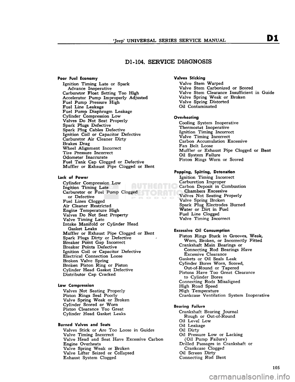
Dl-104.
SERVICE
DIAGNOSIS
Poor Fuel Economy
Ignition Timing Late or Spark Advance Inoperative
Carburetor
Float Setting Too High
Accelerator Pump Improperly Adjusted
Fuel
Pump Pressure High
Fuel
Line
Leakage
Fuel
Pump Diaphragm Leakage
Cylinder
Compression Low
Valves Do Not Seat Properly
Spark
Plugs
Defective
Spark
Plug Cables
Defective
Ignition
Coil
or Capacitor
Defective
Carburetor
Air Cleaner Dirty
Brakes
Drag
Wheel Alignment Incorrect
Tire
Pressure Incorrect Odometer Inaccurate
Fuel
Tank
Cap Clogged or
Defective
Muffler or Exhaust Pipe Clogged or Bent
Lack
of
Power
Cylinder
Compression Low
Ingitdon Timing Late
Carburetor
or
Fuel
Pump Clogged or
Defective
Fuel
Lines Clogged
Air
Cleaner Restricted
Engine Temperature High Valves Do Not Seat Property
Valve
Timing Late Intake Manifold or Cylinder Head
Gasket Leaks
Muffler or Exhaust Pipe Clogged or Bent
Spark
Plugs Dirty or
Defective
Breaker
Point Gap Incorrect
Breaker
Points
Defective
Ignition
Coil
or Capacitor
Defective
Electrical
Connection Loose
Broken
Valve Spring
Broken
Piston Ring or Piston
Cylinder
Head Gasket
Defective
Distributor Cap Cracked
Low
Compression
Valves Not Seating Properly Piston Rings Seal Poorly
Valve
Spring Weak or Broken
Cylinder
Scored or Worn
Piston Clearance Too Great
Cylinder
Head Gasket Leaks
Burned
Valves and
Seats
Valves Stick or Are Too Loose in Guides
Valve
Timing Incorrect
Valve
Head and Seat Have Excessive Carbon
Engine Overheats
Valve
Spring Weak or Broken
Valve
Lifter Seized or Collapsed
Exhaust
System Clogged
Valves Sticking
Valve
Stem Warped
Valve
Stem Carbonized or Scored
Valve
Stem Clearance Insufficient in Guide
Valve
Spring Weak or Broken
Valve
Spring Distorted
Oil
Contaminated
Overheating
Cooling System Inoperative
Thermostat Inoperative Ignition Timing Incorrect
Valve
Timing Incorrect
Carbon
Accumulation Excessive
Fan
Belt Loose
Muffler or Exhaust Pipe Clogged or Bent
Oil
System Failure
Piston Rings Worn or Scored
Popping,
Spitting,
Detonation
Ignition Timing Incorrect
Carburetion
Improper
Carbon
Deposit
in Combustion
Chambers Excessive
Valves Not Seating Properly
Valve
Spring Broken
Spark
Plug Electrodes Burned
Water or Dirt in
Fuel
Fuel
Line
Clogged
Valve
Timing Incorrect
Excessive
Oil
Consumption
Piston Rings Stuck in Grooves, Weak,
Worn,
Broken, or Incorrectly Fitted
Crankshaft
Main Bearings or
Connecting Rod Bearings Have
Excessive Clearance
Gaskets or Oil Seals
Leak
Cylinder
Bores Worn, Scored,
Out-of-Round or Tapered
Pistons Have Too Great Clearance to Cylinder Bores
Connecting Rods Misaligned High Road Speed
High Temperature
Crankcase
Ventilation System Inoperative
Bearing Failure
Crankshaft
Bearing Journal Rough or Out-of-Round
Oil
Level Low
Oil
Leakage
Oil
Dirty
Oil
Pressure Low or Lacking
(Oil
Pump Failure)
Drilled
Passages
in Crankshaft or
Crankcase
Clogged
Oil
Screen Dirty
Connecting Rod Bent 105
Page 107 of 376
'Jeep*
UNIVERSAL
SERIES
SERVICE
MANUAL
Dl
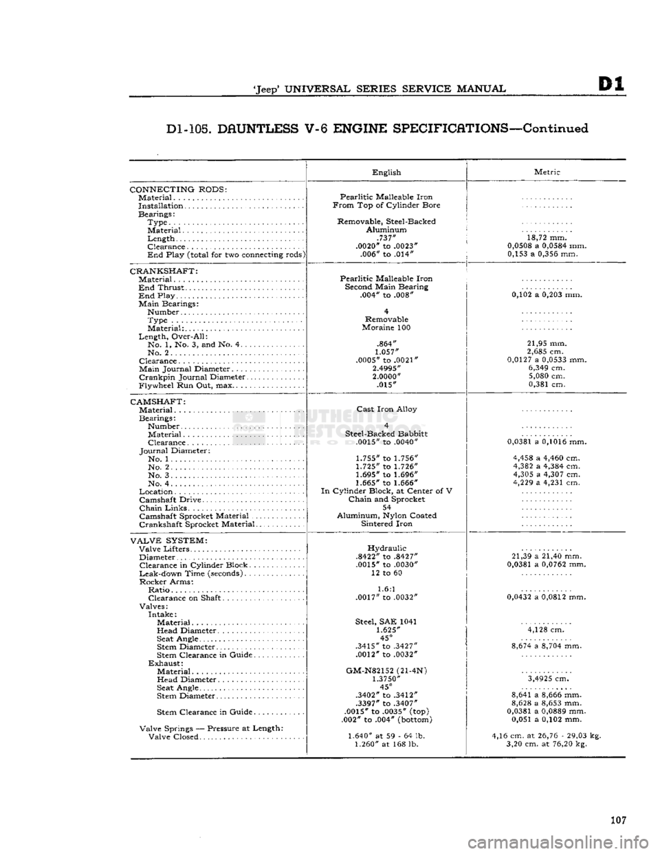
Dl-105.
DAUNTLESS
V-6
ENGINE
SPECIFICATIONS—Continued
CONNECTING
RODS:
Material
Installation
Bearings: Type........
Material.
Length Clearance
End
Play
(total
for two
connecting
rods)
CRANKSHAFT:
Material ,
End
Thrust
End
Play
Main
Bearings: Number Type
Material:
Length, Over-All: No. 1, No. 3, and No. 4
No. 2
Clearance
Main
Journal Diameter.
Crankpin
Journal Diameter
Flywheel Run Out, max
CAMSHAFT:
Material
Bearings: Number Material Clearance
Journal
Diameter: No. 1 No. 2
No. 3.
No. 4
Location Camshaft Drive
Chain
Links
Camshaft Sprocket Material
Crankshaft Sprocket Material
VALVE
SYSTEM:
Valve Lifters Diameter Clearance in Cylinder Block
Leak-down Time
(seconds)
Rocker Arms: Ratio Clearance on Shaft
Valves: Intake: Material
Head Diameter
Seat
Angle
Stem
Diameter
Stem
Clearance in Guide
Exhaust:
Material Head Diameter
Seat
Angle
Stem
Diameter
Stem
Clearance in Guide
Valve Springs — Pressure at Length: Valve Closed English
Pearlitic Malleable Iron
From
Top of Cylinder Bore
Removable, Steel-Backed Aluminum .737"
.0020"
to
.0023"
.006" to .014" Metric
18,72 mm.
0,0508
a
0,0584
mm. 0,153 a
0,356
mm.
Pearlitic Malleable Iron
Second
Main Bearing .004" to .008"
Removable
Moraine 100
.864"
1.057"
.0005"
to
.0021"
2.4995"
2.0000"
.015" 0,102 a
0,203
mm.
21,95 mm.
2,685
cm.
0,0127
a
0,0533
mm.
6,349
cm.
5,080
cm.
0,381 cm.
Cast
Iron Alloy
Steel-Backed Babbitt
.0015"
to
.0040"
1.755"
to
1.756"
1.725"
to
1.726"
1.695"
to
1.696"
1.665"
to
1.666"
In
Cylinder Block, at Center of V
Chain
and Sprocket 54
Aluminum,
Nylon
Coated Sintered Iron
0,0381
a
0,1016
mm.
4,458
a
4,460
cm.
4,382
a
4,384
cm.
4,305
a
4,307
cm.
4,229
a 4,231 cm.
Hydraulic
.8422"
to
.8427"
.0015"
to
.0030"
12 to 60
1.6:1
.0017"
to
.0032"
Steel,
SAE 1041
1.625"
45°
.3415"
to
.3427"
.0012"
to
.0032"
GM-N82152
(21-4N)
1.3750"
45°
.3402"
to
.3412"
.3397"
to
.3407"
.0015"
to
.0035"
(top)
.002" to .004"
(bottom)
1.640"
at 59 - 64 lb.
1.260"
at 168 lb. 21,39 a 21,40 mm.
0,0381
a
0,0762
mm.
0,0432
a
0,0812
mm. 4,128 cm.
8,674
a
8,704
mm.
3,4925
cm.
8,641 a
8,666
mm.
8,628
a
8,653
mm.
0,0381
a
0,0889
mm. 0,051 a 0,102 mm.
4,16 cm. at
26,76
-
29,03
kg. 3,20 cm. at
76,20
kg.
107
Page 109 of 376
'Jeep*
UNIVERSAL SERIES SERVICE
MANUAL
E
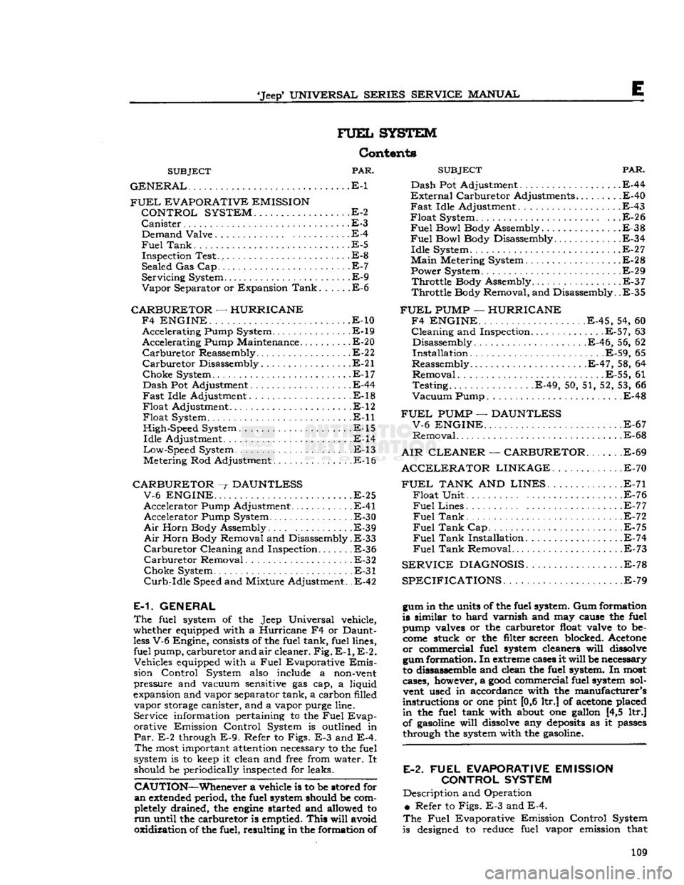
FUEL
SYSTEM
Contents
SUBJECT
PAR.
GENERAL
E-1 Dash
FUEL
EVAPORATIVE EMISSION
?*^r
CONTROL SYSTEM
..E-2
Canister
.E-3 . Demand Valve E-4
Fuel
Tank.
.E-5
Inspection Test. E-8
Sealed Gas Cap. E-7
Servicing
System E-9
Vapor
Separator or Expansion
Tank
E-6
CARBURETOR
—
HURRICANE F4 ENGINE.
. .
......
..... ,. . .E-10 Accelerating Pump System.............. .E-19 Accelerating Pump Maintenance E-20
Carburetor
Reassembly
E-2
2
Carburetor
Disassembly E-21
Choke
System E-17
Dash
Pot Adjustment E-44
Fast
Idle Adjustment E-18
Float
Adjustment E-12
Float
System. E-ll
High-Speed System . .E-15
Idle
Adjustment .E-14
Low-Speed
System . E-13
Metering Rod Adjustment E-16
CARBURETOR
~r
DAUNTLESS V-6 ENGINE
.E-25
Accelerator Pump Adjustment E-41 Accelerator Pump System. . E-30
Air
Horn Body Assembly E-39
Air
Horn Body Removal and Disassembly.
E-33
Carburetor
Cleaning and Inspection E-36
Carburetor
Removal E-32
Choke
System E-31
Curb-Idle
Speed and Mixture Adjustment. .E-42
E-1. GENERAL
The
fuel system of the Jeep Universal vehicle,
whether equipped with a Hurricane F4 or Daunt
less
V-6 Engine,
consists
of the fuel tank, fuel lines, fuel pump, carburetor and
air
cleaner.
Fig. E-1, E-2.
Vehicles equipped with a
Fuel
Evaporative
Emis
sion Control System
also
include a
non-vent
pressure and vacuum
sensitive
gas cap, a liquid
expansion and vapor separator tank, a carbon filled vapor
storage
canister, and a vapor purge line. Service information pertaining to the
Fuel
Evap
orative Emission Control System is outlined in
Par.
E-2 through
E-9.
Refer to Figs. E-3 and E-4.
The
most
important
attention
necessary to the fuel
system is to
keep
it clean and free from water. It should be periodically inspected for leaks.
CAUTION—Whenever
a vehicle is to be stored for
an
extended
period, the fuel system should be com
pletely
drained, the
engine
started and allowed to
run
until the carburetor is emptied.
This
will
avoid
oxidization of the fuel, resulting in the formation of
SUBJECT
PAR.
Pot Adjustment .E-44
nal
Carburetor Adjustments.........E-40
Idle
Adjustment
.
E-43 System . . .E-26
Bowl
Body Assembly E-38
Fuel
Bowl Body Disassembly E-34
Idle
System E-27
Main
Metering System E-28
Power System . E-29
Throttle
Body Assembly .E-37
Throttle
Body Removal, and Disassembly. .E-35
FUEL
PUMP
—
HURRICANE F4 ENGINE.
E-45, 54, 60
Cleaning
and Inspection.............
.E-57,
63 Disassembly E-46, 56, 62
Installation E-59, 65
Reassembly
.E-47,
58, 64
Removal
E-55, 61
Testing.
E-49, 50, 51, 52, 53, 66
Vacuum
Pump E-48
FUEL
PUMP
—
DAUNTLESS V-6 ENGINE
E-67
Removal
E-68
AIR CLEANER
—
CARBURETOR
E-69
ACCELERATOR
LINKAGE
.E-70
FUEL
TANK
AND
LINES
E-71
Float
Unit . .E-76
Fuel
Lines E-77
Fuel
Tank
. . .E-72
Fuel
Tank
Cap E-75
Fuel
Tank
Installation. E-74
Fuel
Tank
Removal E-73
SERVICE
DIAGNOSIS
E-78
SPECIFICATIONS.
E-79
gum in the units of the fuel system. Gum formation
is similar to hard varnish and may cause the fuel
pump valves or the carburetor
float
valve to be
come
stuck or the filter screen blocked. Acetone or commercial fuel system cleaners
will
dissolve
gum formation. In
extreme
cases
it
will
be necessary
to dissassemble and clean the fuel system. In
most
cases, however, a
good
commercial fuel system sol
vent
used in accordance with the manufacturer's
instructions or one pint [0,6 ltr.] of
acetone
placed
in
the fuel tank with
about
one gallon [4,5 ltr.]
of
gasoline
will
dissolve
any
deposits
as it
passes
through the system with the
gasoline.
E-2.
FUEL
EVAPORATIVE EMISSION CONTROL SYSTEM
Description and Operation
•
Refer to Figs. E-3 and E-4.
The
Fuel
Evaporative Emission Control System
is
designed
to reduce fuel vapor emission that 109
Page 111 of 376
'Jeep*
UNIVERSAL
SERIES
SERVICE
MANUAL
E
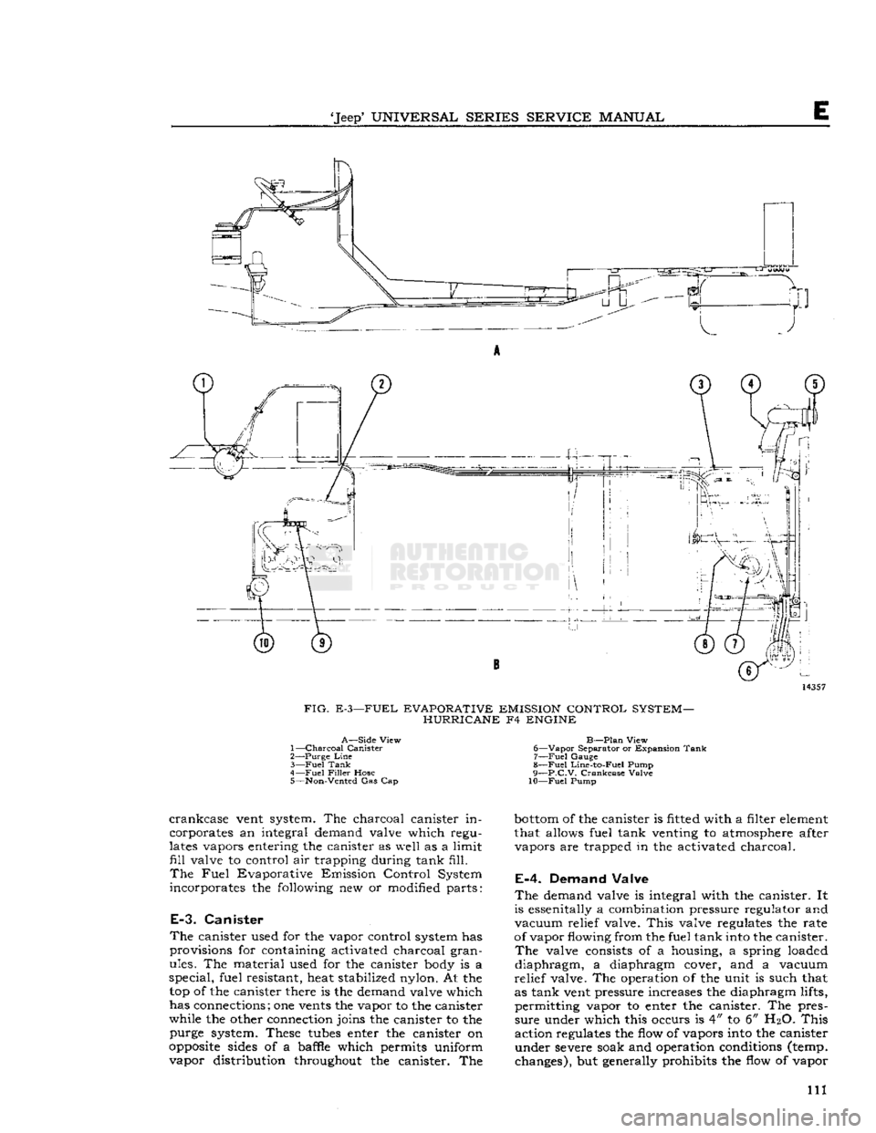
FIG.
E-3—FUEL EVAPORATIVE EMISSION CONTROL SYSTEM- HURRICANE F4 ENGINE
A—Side
View
1—
Charcoal Canister
2— Purge
Line
3—
Fuel
Tank
4—
Fuel
Filler
Hose 5—
Non-Vented
Gas Cap
B—Plan
View
6—
Vapor
Separator
or Expansion Tank 7—
Fuel
Gauge
8—
Fuel
Line-to-Fuel Pump
9—
p.C.V.
Crankcase
Valve
10—Fuel
Pump
crankcase
vent system. The charcoal canister in
corporates an integral demand valve
which
regu
lates
vapors entering the canister as
well
as a
limit
fill
valve
to control air trapping during tank
fill.
The
Fuel
Evaporative Emission Control System
incorporates the following new or modified parts:
E-3.
Canister
The canister used for the vapor control system has
provisions for containing activated charcoal gran ules. The material used for the canister body is a
special,
fuel resistant, heat stabilized nylon. At the top of the canister there is the demand valve which
has connections; one vents the vapor to the canister
while the other connection joins the canister to the purge system. These
tubes
enter the canister on
opposite
sides of a baffle which permits uniform
vapor distribution throughout the canister. The
bottom
of the canister is fitted with a filter element
that allows fuel tank venting to atmosphere after vapors are trapped in the activated charcoal.
E-4.
Demand Valve
The
demand valve is integral with the canister. It
is essenitally a combination pressure regulator and
vacuum
relief valve.
This
valve regulates the rate
of vapor
flowing
from the fuel tank into the canister.
The
valve consists of a housing, a spring loaded
diaphragm,
a diaphragm cover, and a vacuum
relief
valve. The operation of the unit is such that
as tank vent pressure increases the diaphragm lifts,
permitting vapor to enter the canister. The pres
sure
under which this occurs is 4" to 6"
H2O.
This
action regulates the flow of vapors into the canister
under severe soak and operation conditions (temp, changes), but generally prohibits the flow of vapor 111
Page 113 of 376
'Jeep*
UNIVERSAL
SERIES
SERVICE
MANUAL
E
there is a relief valve that
opens
to reduce high
(dangerous) pressures in the fuel tank. In con
junction
with the pressure relief valve there is a
vacuum
relief valve to
stop
collapse of the fuel
tank
in case of a plugged system or failure of the demand valve. When replacing the gas cap, the
same type must be used as originally installed.
E-8.
System Inspection Test
The
fuel emission vent system should be checked
carefully
to ensure the absence of any leaks to the
atmosphere of either liquid or vapor which might
affect the accuracy, safety, or performance of the control system.
To
assure that the sealed system has been properly
installed,
the following
test
procedure has been
developed.
Disconnect the vent line from the fuel tank system
to the activated charcoal canister, induce l/i p.s.i.
air
pressure. If this pressure can be maintained for
a
few seconds the vent system is assured to be sealed. DO NOT add air pressure to the canister
because damage can occur to the demand valve if
care
is not taken.
E-9.
Servicing the System
Periodic
Maintenance — Replace carbon canister filter at
12,000
miles
[19,200
km.] or 12 month intervals (more
often
for operation in dusty areas).
This
is the only regular maintenance service
required.
Canister
Filter
Replacement — Disconnect
hoses
from
top of canister, remove canister from mount
-
t
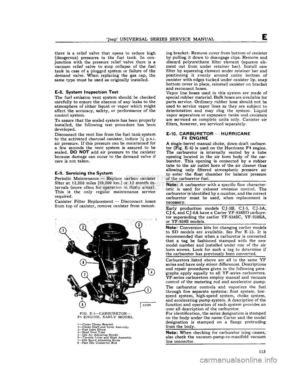
FIG.
E-5—CARBURETOR—
F4 ENGINE,
EARLY
MODEL
1—
Choke
Clamp
Bracket
2—
Choke
Shaft and
Lever
Assembly
3—
Fuel
Inlet
Elbow
4—
Bowl
Vent Tube 5—
Idle
Air Adjusting
Needle
6—
Throttle
Lever
and Shaft Assembly
7—
Idle
Speed Adjusting Screw
8—
Fast
Idle Connector Rod ing bracket. Remove cover from
bottom
of canister
by pulling it down to
disengage
clips. Remove and
discard
polyurethane filter element
(squeeze
ele
ment out from under retainer bar).
Install
new
filter by squeezing element under retainer bar and positioning it evenly around entire
bottom
of
canister with
edges
tucked under canister lip, snap
bottom
cover in place, reinstall canister on bracket
and
reconnect
hoses.
Vapor
line
hoses
used in this system are made of
special
rubber material.
Bulk
hoses
are available for
parts
service.
Ordinary
rubber
hose
should not be
used to service vapor lines as they are subject to deterioration and may clog the system.
Liquid
vapor separators or expansion tanks and canisters
are
serviced as complete units only.
Canister
air filters, however, are serviced separately.
E-10.
CARBURETOR
—
HURRICANE
F4
ENGINE
A
single-barrel manual choke, down-draft carbure
tor (Fig. E-6) is used on the
Hurricane
F4 engine.
The
carburetor is internally vented by a tube
opening located in the air horn body of the
car
buretor.
This
opening is connected by a rubber
tube to the air
outlet
horn of the air cleaner thus
allowing only filtered atmospheric pressure air
to enter the float chamber for balance pressure
of the carburetor fuel.
Note:
A carburetor with a specific flow character
istic
is used for exhaust emission control. The
carburetor
is identified by a number, and the correct
carburetor
must be used, when replacement is
necessary.
Early
production models
CJ-3B,
CJ-5,
CJ-5A,
CJ-6,
and
CJ-6A
have a
Carter
YF-938SD
carbure
tor superseding the earlier
YF-938SC,
YF-938SA,
or
YF-938S
models.
Note."
Conversion kits for changing earlier models
to SD models are available. See Par E-23. It is recommended that when a carburetor is converted
that a tag be fashioned stamped with the new model number and installed under one of the air
horn
screws.
Look
for such a tag to determine if
the carburetor has previously been converted.
Carburetors
listed above are all in the same YF
series and have only minor differences. Descriptions
and
repair procedures given in the following
para
graphs apply equally to all
YF-series
carburetors.
YF-series
carburetors employ manual and vacuum
control of the metering rod and accelerator pump.
The
carburetor controls and vaporizes the fuel
through five separate systems: float system, low-
speed system, high-speed system, choke system,
and
accelerating-pump system. A description of the function and operation of each system provides an over all description of the carburetor.
For
identification, the series designation is stamped
on the body under the name
Carter
and the model
designation is stamped on a flange protruding
from
the body.
Note:
When checking for carburetor icing causes,
also check the vacuum-pump-to-manifold vacuum
line connector. 113
Page 115 of 376
'Jeep*
UNIVERSAL
SERIES
SERVICE
MANUAL
E
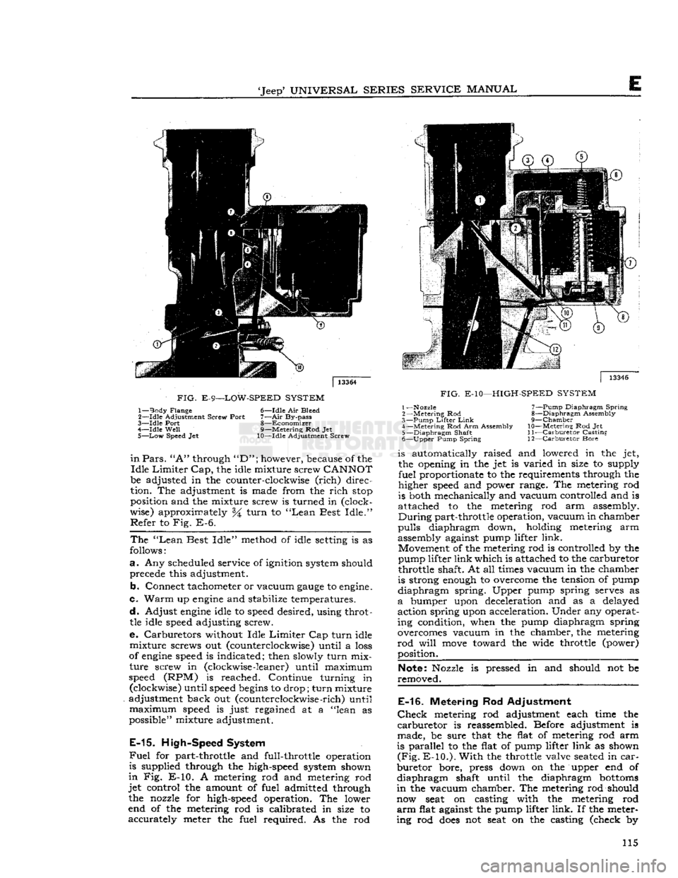
FIG.
E-9—LOW-SPEED
SYSTEM
1—
Body
Flange 6—Idle Air Bleed
2—
-Idle
Adjustment Screw Port
7—Air
By-pass
3—
Idle
Port 8—Economizer
4—
Idle
Well
9—Metering Rod Jet
5—
Low
Speed Jet 10—Idle Adjustment Screw
in
Pars.
"A"
through
"D";
however, because of the
Idle
Limiter
Cap,
the idle mixture screw
CANNOT
be adjusted in the counter-clockwise
(rich)
direc
tion. The adjustment is made from the
rich
stop
position and the mixture screw is turned in (clock
wise) approximately %
turn
to
"Lean
Best
Idle."
Refer
to Fig. E-6.
The
"Lean
Best
Idle"
method of idle
setting
is as
follows:
a.
Any scheduled service of ignition system should precede this adjustment.
b.
Connect tachometer or vacuum
gauge
to
engine.
c.
Warm
up
engine
and stabilize temperatures.
d.
Adjust
engine
idle to
speed
desired, using throttle idle
speed
adjusting screw.
e. Carburetors without Idle
Limiter
Cap
turn
idle
mixture
screws out (counterclockwise) until a
loss
of
engine
speed
is indicated; then slowly
turn
mix
ture
screw in (clockwise
-leaner)
until maximum
speed
(RPM) is reached. Continue turning in (clockwise) until
speed
begins
to drop;
turn
mixture
adjustment back out (counterclockwise
-rich)
until
maximum
speed
is just regained at a "lean as
possible" mixture adjustment.
E-15.
High-Speed System
Fuel
for part-throttle and full-throttle operation
is supplied through the high-speed system shown
in
Fig. E-10. A metering rod and metering rod
jet
control the amount of fuel admitted through the nozzle for high-speed operation. The lower
end of the metering rod is calibrated in size to
accurately
meter the fuel required. As the rod
|
13346
FIG.
E-10—HIGH-SPEED
SYSTEM
1—Nozzle 7—Pump Diaphragm
Spring
2
—Metering
Rod 8—Diaphragm Assembly
3—
Pump
Lifter
Link
9—Chamber
4—
Metering
Rod Arm Assembly
10—Metering
Rod Jet 5—
Diaphragm
Shaft
11—Carburetor
Casting
6—
Upper
Pump Spring 12—Carburetor Bore is automatically raised and lowered in the jet,
the opening in the jet is varied in size to supply
fuel
proportionate to the requirements through the
higher
speed
and power range. The metering rod
is both mechanically and vacuum controlled and is
attached to the metering rod arm assembly.
During
part-throttle operation, vacuum in chamber
pulls
diaphragm down, holding metering arm
assembly against pump lifter
link.
Movement of the metering rod is controlled by the
pump lifter
link
which is attached to the carburetor
throttle shaft. At all
times
vacuum in the chamber
is strong
enough
to overcome the tension of pump
diaphragm
spring. Upper pump spring serves as
a
bumper upon deceleration and as a delayed
action spring upon acceleration. Under any operat ing condition, when the pump diaphragm spring
overcomes vacuum in the chamber, the metering
rod
will
move
toward the wide throttle (power) position.
Note:
Nozzle is pressed in and should not be
removed.
E-16.
Metering Rod Adjustment
Check
metering rod adjustment each time the
carburetor
is reassembled. Before adjustment is
made, be sure that the flat of metering rod arm
is parallel to the flat of pump lifter
link
as shown
(Fig.
E-10.).
With
the throttle valve
seated
in
car
buretor
bore, press down on the upper end of
diaphragm
shaft until the diaphragm
bottoms
in
the vacuum chamber. The metering rod should
now
seat
on casting with the metering rod
arm
flat against the pump lifter
link.
If the meter
ing rod
does
not
seat
on the casting (check by 115
Page 117 of 376
'Jeep*
UNIVERSAL
SERIES
SERVICE
MANUAL
E
Note:
The
Carter
YF-6115S Carburetor has a
throttle
return spring
attached
from the carburetor
main
body
to the carburetor
throttle
shaft. The
purpose
of
this
spring is to return the
throttle
to
idle
speed
position
should a linkage failure occur.
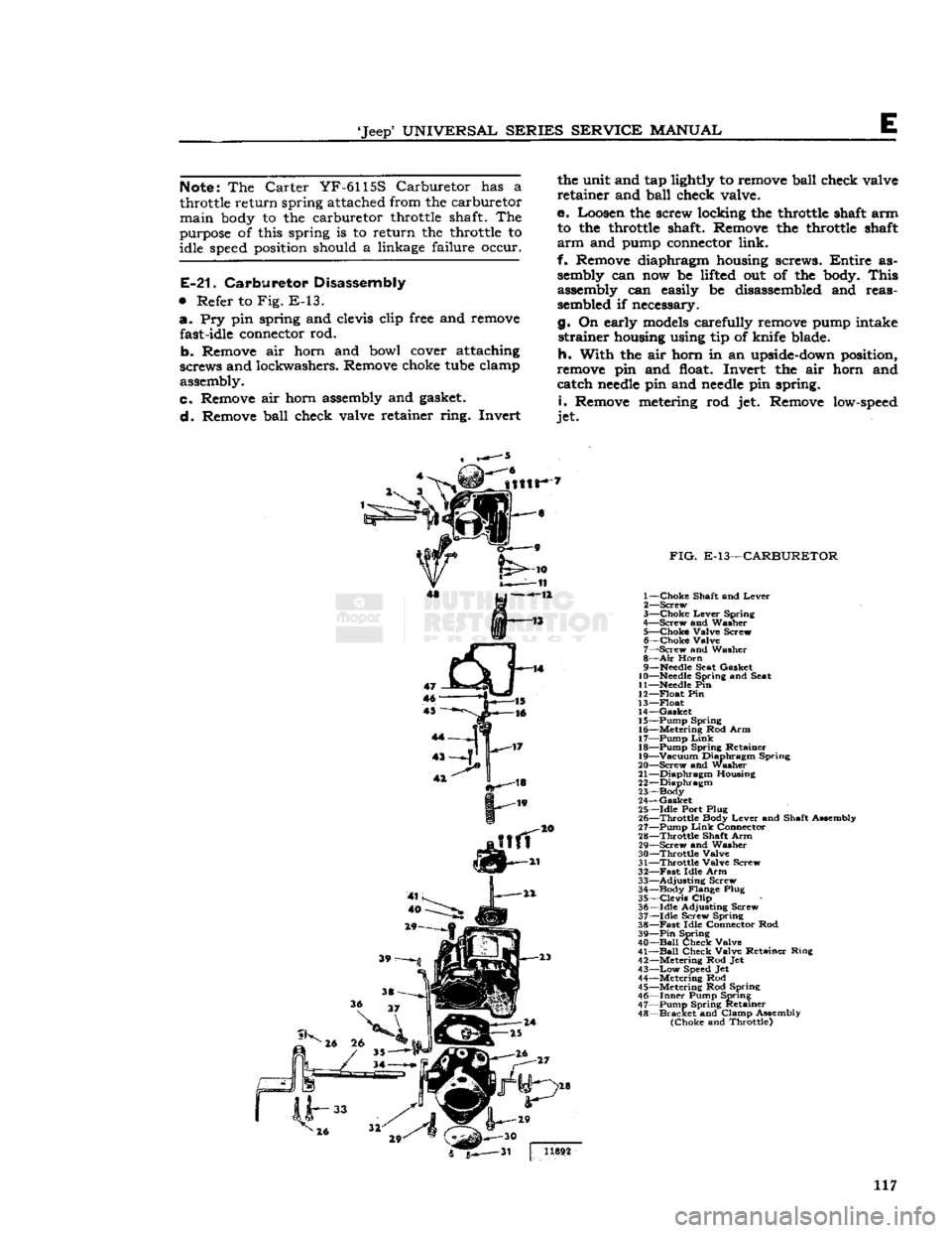
E-21.
Carburetor Disassembly
•
Refer to Fig. E-13. a. Pry pin spring and
clevis
clip
free
and
remove
fast-idle
connector
rod.
b- Remove air horn and bowl
cover
attaching
screws and lockwashers. Remove
choke
tube
clamp
assembly.
c. Remove air horn
assembly
and
gasket.
d. Remove ball check valve retainer ring. Invert the unit and tap
lightly
to
remove
ball check valve
retainer and ball check valve.
e. Loosen the screw locking the
throttle
shaft
arm to the
throttle
shaft. Remove the
throttle
shaft
arm
and
pump
connector
link.
f. Remove diaphragm
housing
screws.
Entire
as
sembly
can now be
lifted
out of the
body.
This
assembly
can easily be
disassembled
and reas
sembled
if necessary.
g. On early
models
carefully
remove
pump
intake strainer
housing
using tip of knife blade.
h. With the air horn in an
upside-down
position,
remove
pin and
float.
Invert the air horn and catch
needle
pin and
needle
pin spring.
i.
Remove
metering
rod jet. Remove
low-speed
jet.
FIG.
E-13—CARBURETOR
1— Choke Shaft and Lever
2— Screw
3— Choke Lever Spring
4— Screw and Washer
5— Choke Valve Screw 6— Choke Valve
7— Screw and Washer
8—
Air
Horn
9—
Needle
Seat Gasket
10—
Needle
Spring and Seat
11—Needle
Pin
12— Float Pin
13— Float
14— Gasket 15— Pump Spring
16— Metering Rod Arm
17— Pump
Link
18— Pump Spring Retainer
19— Vacuum Diaphragm Spring
20— Screw and washer
21— Diaphragm Housing
22— Diaphragm
23—Body
24— Gasket
25— Idle Port Plug
26— Throttle Body Lever and Shaft Assembly
27— Pump
Link
Connector
28— Throttle Shaft Arm 29— Screw and Washer
30— Throttle Valve
31— Throttle Valve Screw
32—
Fast
Idle Arm 33— Adjusting Screw
34— Body Flange Plug
35— Clevis
Clip
36— Idle Adjusting Screw
37— Idle Screw Spring
38—
Fast
Idle Connector Rod 39—
Pin
Spring
40—
Ball
Check Valve
41—
Ball
Check Valve Retainer Ring
42— Metering Rod Jet
43—
Low
Speed
Jet
44— Metering Rod
45— Metering Rod Spring 46—
Inner
Pump Spring
47— Pump Spring Retainer
48—
Bracket
and Clamp Assembly (Choke and Throttle) 5^—31 | 1X892
117
Page 119 of 376
'Jeep'
UNIVERSAL
SERIES SERVICE
MANUAL
E
FIG.
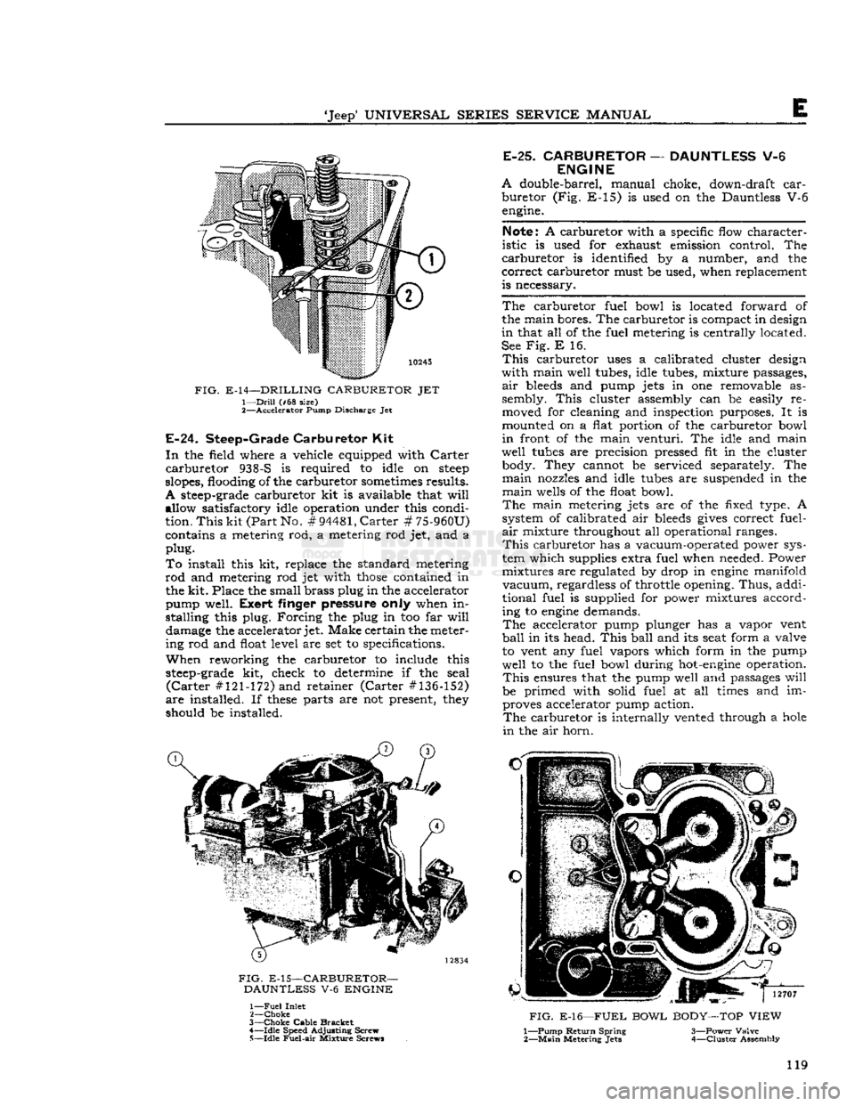
E-14—DRILLING CARBURETOR JET 1—
Drill
(#68 size)
2—
Accelerator
Pump Discharge Jet
E-24.
Steep-Grade
Carburetor
Kit
In
the
field
where a vehicle equipped
with
Carter carburetor 938-S is required to
idle
on
steep
slopes,
flooding
of the carburetor sometimes results.
A
steep-grade
carburetor kit is available that
will
allow satisfactory
idle
operation under this condi
tion.
This kit (Part
No.
#94481,
Carter # 75-960U)
contains a metering rod, a metering rod jet, and a
plug.
To
install
this kit, replace the standard metering
rod
and metering rod jet
with
those
contained in the
kit.
Place the small
brass
plug
in the accelerator
pump
well.
Exert
finger pressure only when in
stalling
this
plug.
Forcing the
plug
in too far
will
damage
the accelerator
jet.
Make certain the meter
ing
rod and
float
level
are set to specifications.
When
reworking
the carburetor to include this
steep-grade
kit, check to determine if the seal (Carter #121-172) and retainer (Carter #136-152)
are installed. If
these
parts are not present, they
should
be installed.
FIG.
E-15—CARBURETOR-
DAUNTLESS V-6 ENGINE 1—
Fuel
Inlet
2—
Choke
3—
Choke
Cable
Bracket
4—
Idle
Speed Adjusting Screw 5—
Idle
Fuel-air
Mixture Screws
E-25.
CARBURETOR
—
DAUNTLESS
V-6
ENGINE
A
double-barrel, manual choke, down-draft car
buretor (Fig. E-15) is used on the Dauntless V-6 engine.
Note: A carburetor
with
a specific
flow
character
istic
is used for exhaust emission
control.
The
carburetor is
identified
by a number, and the
correct carburetor must be used, when replacement
is
necessary.
The carburetor
fuel
bowl
is located
forward
of
the main bores. The carburetor is compact in design
in
that all of the
fuel
metering is centrally located.
See Fig. E 16.
This
carburetor
uses
a calibrated cluster design
with
main
well
tubes,
idle
tubes, mixture
passages,
air
bleeds and pump jets in one removable as
sembly.
This cluster assembly can be easily re
moved
for cleaning and inspection purposes. It is
mounted
on a
flat
portion
of the carburetor
bowl
in
front
of the main
venturi.
The
idle
and main
well
tubes
are precision
pressed
fit in the cluster
body.
They cannot be serviced separately. The
main
nozzles and
idle
tubes
are
suspended
in the
main
wells of the
float
bowl.
The main metering jets are of the
fixed
type. A
system of calibrated air bleeds gives correct
fuel-
air
mixture throughout all operational
ranges.
This
carburetor has a vacuum-operated power sys
tem
which
supplies extra
fuel
when needed. Power
mixtures
are regulated by drop in engine
manifold
vacuum,
regardless of throttle opening. Thus, addi
tional
fuel
is supplied for power mixtures accord
ing
to engine demands.
The accelerator pump plunger has a vapor vent
ball
in its head. This
ball
and its
seat
form
a valve
to
vent any
fuel
vapors
which
form
in the pump
well
to the
fuel
bowl
during hot-engine operation.
This
ensures
that the pump
well
and
passages
will
be primed
with
solid
fuel
at all times and im proves accelerator pump action. The carburetor is
internally
vented through a hole
in
the air horn.
FIG.
E-16—FUEL BOWL BODY—TOP VIEW
1— Pump Return Spring 3—Power
Valve
2—
Main
Metering
Jets
4—Cluster Assembly
119
Page 121 of 376
'Jeep'
UNIVERSAL SERIES SERVICE
MANUAL
FIG.
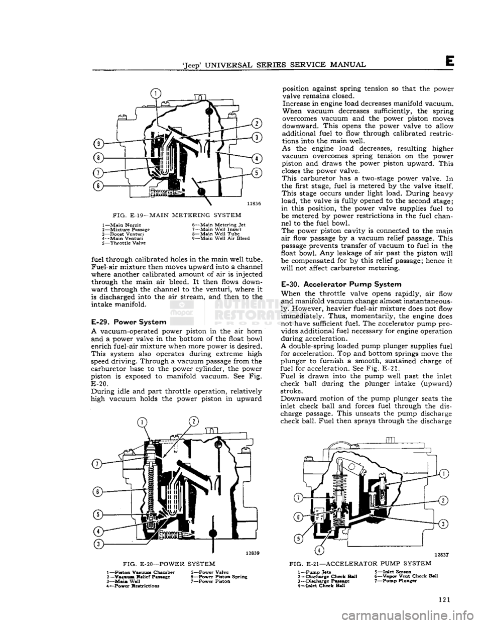
E-19—
MAIN
METERING SYSTEM
1—
Main
Nozzle
2—
Mixture
Passage
3—
Boost
Venturi
4—
Main
Venturi
5—
Throttle
Valve 6—
Main
Metering Jet
7—
Main
Well
Insert
8—
Main
Well
Tube
9—
Main
Well
Air Bleed fuel through calibrated
holes
in the main well tube.
Fuel-air
mixture then
moves
upward into a channel
where another calibrated amount of air is injected through the main air bleed. It then flows down
ward
through the channel to the venturi, where it is discharged into the air stream, and then to the
intake manifold.
E-29.
Power System
A
vacuum-operated power piston in the air horn
and
a power valve in the
bottom
of the float bowl
enrich
fuel-air mixture when more power is desired.
This
system also operates during extreme high
speed driving. Through a vacuum passage from the
carburetor
base to the power cylinder, the power
piston is
exposed
to manifold vacuum. See Fig.
E-20.
During
idle and part throttle operation, relatively
high vacuum holds the power piston in upward
FIG.
E-20—POWER
SYSTEM
position against spring tension so that the power
valve remains closed.
Increase
in
engine
load decreases manifold vacuum.
When
vacuum decreases sufficiently, the spring
overcomes vacuum and the power piston
moves
downward.
This
opens
the power valve to allow
additional fuel to flow through calibrated restric
tions into the main well.
As
the
engine
load decreases, resulting higher
vacuum
overcomes spring tension on the power
piston and draws the power piston upward.
This
closes
the power valve.
This
carburetor has a
two-stage
power valve. In
the first
stage,
fuel is metered by the valve itself.
This
stage
occurs under light load. During heavy
load,
the valve is fully opened to the second
stage;
in
this position, the power valve supplies fuel to
be metered by power restrictions in the fuel chan
nel
to the fuel bowl.
The
power piston cavity is connected to the main
air
flow passage by a vacuum relief passage.
This
passage prevents transfer of vacuum to fuel in the
float bowl. Any leakage of air past the piston
will
be compensated for by this relief passage; hence it
will
not affect carburetor metering.
E-30.
Accelerator Pump System
When
the throttle valve
opens
rapidly, air flow
and
manifold vacuum change almost instantaneous
ly.
However, heavier fuel-air mixture
does
not flow immediately.
Thus,
momentarily, the
engine
does
not have sufficient fuel. The accelerator pump pro vides additional fuel necessary for
engine
operation
during
acceleration.
A
double-spring loaded pump plunger supplies fuel for acceleration. Top and
bottom
springs
move
the
plunger to furnish a smooth, sustained charge of
fuel for acceleration. See Fig. E-21.
Fuel
is drawn into the pump well past the inlet
check ball during the plunger intake (upward)
stroke.
Downward
motion of the pump plunger
seats
the
inlet check ball and forces fuel through the dis charge
passage.
This
unseats
the pump discharge
check
ball.
Fuel
then sprays through the discharge
12837
FIG.
E-21—ACCELERATOR
PUMP
SYSTEM
1— Piston Vacuum Chamber
2—
Vacuus*
Relief Passage
3—
Main
Well
4— ^Power Restrictions 5— Power Valve
6— Power Piston Spring 7— Power Piston 1— Pump
Jets
2—
Discharge
Check
Ball
3—
Discharge
Passage
4—
Inlet
Check
Ball
5—
Inlet
Screen
6—
Vapor
Vent
Check
Ball
7—
Pump
Plunger
121