wheel torque JEEP COMPASS 2014 1.G User Guide
[x] Cancel search | Manufacturer: JEEP, Model Year: 2014, Model line: COMPASS, Model: JEEP COMPASS 2014 1.GPages: 124, PDF Size: 2.64 MB
Page 78 of 124

FOUR-WHEEL DRIVE OPERATION
This vehicle has two full time, on-demand, four-wheel-drive (4WD) systems avail-
able, Freedom Drive I™ and Freedom-Drive II™. They provide for all-weather,
all-terrain capability for added driving security in less-than-ideal road conditions.
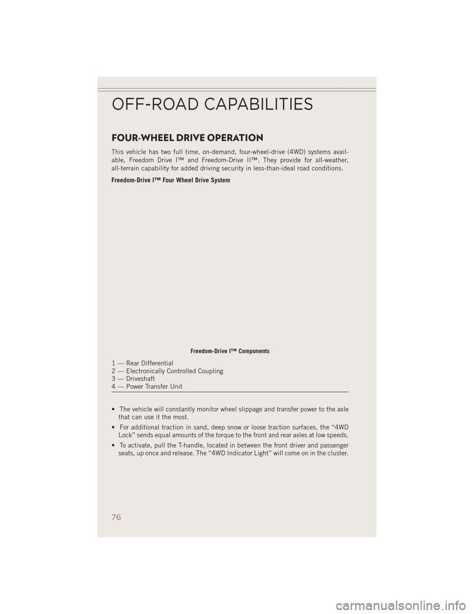
Freedom-Drive I™ Four Wheel Drive System
• The vehicle will constantly monitor wheel slippage and transfer power to the axlethat can use it the most.
• For additional traction in sand, deep snow or loose traction surfaces, the “4WD Lock” sends equal amounts of the torque to the front and rear axles at low speeds.
• To activate, pull the T-handle, located in between the front driver and passenger seats, up once and release. The “4WD Indicator Light” will come on in the cluster.
Freedom-Drive I™ Components
1 — Rear Differential
2 — Electronically Controlled Coupling
3 — Driveshaft
4 — Power Transfer Unit
OFF-ROAD CAPABILITIES
76
Page 90 of 124

• For vehicles equipped with plastic trim, the plastic has been cut away to exposethe jacking locations in the body.
• Do not raise the vehicle until you are sure the jack is securely engaged.
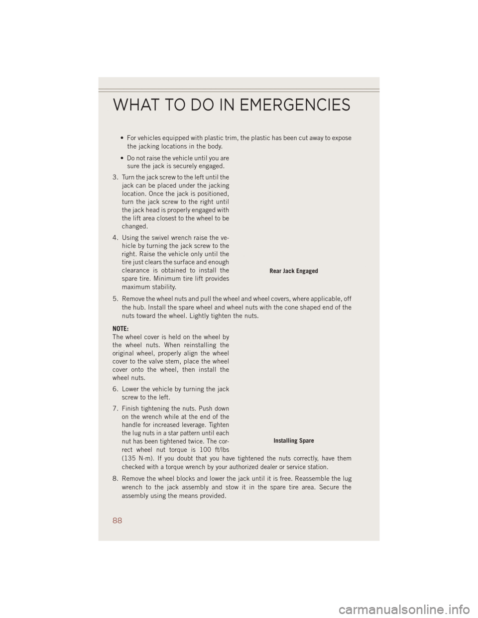
3. Turn the jack screw to the left until the jack can be placed under the jacking
location. Once the jack is positioned,
turn the jack screw to the right until
the jack head is properly engaged with
the lift area closest to the wheel to be
changed.
4. Using the swivel wrench raise the ve- hicle by turning the jack screw to the
right. Raise the vehicle only until the
tire just clears the surface and enough
clearance is obtained to install the
spare tire. Minimum tire lift provides
maximum stability.
5. Remove the wheel nuts and pull the wheel and wheel covers, where applicable, off the hub. Install the spare wheel and wheel nuts with the cone shaped end of the
nuts toward the wheel. Lightly tighten the nuts.
NOTE:
The wheel cover is held on the wheel by
the wheel nuts. When reinstalling the
original wheel, properly align the wheel
cover to the valve stem, place the wheel
cover onto the wheel, then install the
wheel nuts.
6. Lower the vehicle by turning the jack screw to the left.
7.
Finish tightening the nuts. Push down
on the wrench while at the end of the
handle for increased leverage. Tighten
the lug nuts in a star pattern until each
nut has been tightened twice. The cor-
rect wheel nut torque is 100 ft/lbs
(135 N·m). If you doubt that you have tightened the nuts correctly, have them
checked with a torque wrench by your authorized dealer or service station.
8. Remove the wheel blocks and lower the jack until it is free. Reassemble the lug wrench to the jack assembly and stow it in the spare tire area. Secure the
assembly using the means provided.
Rear Jack Engaged
Installing Spare
WHAT TO DO IN EMERGENCIES
88
Page 91 of 124

9. Place the deflated (flat) tire in the cargo area,have the tire repaired or replaced as
soon as possible.
10. Check the spare tire pressure as soon as possible. Correct the tire pressure as required.
Road Tire Installation
Vehicles Equipped With Wheel Covers
1. Mount the road tire on the axle.
2. To ease the installation process for steel wheels with wheel covers, install two lugnuts on the mounting studs which are on each side of the valve stem. Install the
lug nuts with the cone shaped end of the nut toward the wheel. Lightly tighten the
lug nuts.
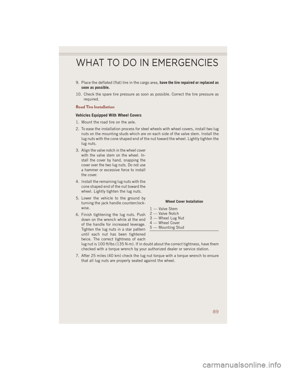
3.
Align the valve notch in the wheel cover
with the valve stem on the wheel. In-
stall the cover by hand, snapping the
cover over the two lug nuts. Do not use
a hammer or excessive force to install
the cover.
4. Install the remaining lug nuts with the cone shaped end of the nut toward the
wheel. Lightly tighten the lug nuts.
5. Lower the vehicle to the ground by turning the jack handle counterclock-
wise.
6. Finish tightening the lug nuts. Push down on the wrench while at the end
of the handle for increased leverage.
Tighten the lug nuts in a star pattern
until each nut has been tightened
twice. The correct tightness of each
lug nut is 100 ft/lbs (135 N·m). If in doubt about the correct tightness, have them
checked with a torque wrench by your authorized dealer or service station.
7. After 25 miles (40 km) check the lug nut torque with a torque wrench to ensure that all lug nuts are properly seated against the wheel.
Wheel Cover Installation
1 — Valve Stem
2 — Valve Notch
3 — Wheel Lug Nut
4 — Wheel Cover
5 — Mounting Stud
WHAT TO DO IN EMERGENCIES
89
Page 92 of 124

Vehicles Without Wheel Covers
1. Mount the road tire on the axle.
2. Install the remaining lug nuts with the cone shaped end of the nut toward thewheel. Lightly tighten the lug nuts.
3. Lower the vehicle to the ground by turning the jack handle counterclockwise.
4. Finish tightening the lug nuts. Push down on the wrench while at the end of the handle for increased leverage. Tighten the lug nuts in a star pattern until each nut
has been tightened twice. The correct tightness of each lug nut is 100 ft/lbs
(135 N·m). If in doubt about the correct tightness, have them checked with a
torque wrench by your authorized dealer or service station.
5. After 25 miles (40 km) check the lug nut torque with a torque wrench to ensure that all lug nuts are properly seated against the wheel.
CAUTION!
• Do not attempt to raise the vehicle by jacking on locations other than thoseindicated in the Jacking Instructions for this vehicle.
• Be sure to mount the spare tire with the valve stem facing outward. The vehicle
could be damaged if the spare tire is mounted incorrectly.
WHAT TO DO IN EMERGENCIES
90