set clock JEEP DJ 1953 User Guide
[x] Cancel search | Manufacturer: JEEP, Model Year: 1953, Model line: DJ, Model: JEEP DJ 1953Pages: 376, PDF Size: 19.96 MB
Page 144 of 376

Fl
EXHAUST EMISSION CONTROL SYSTEMS
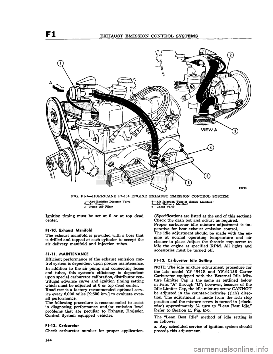
12793
FIG.
Fl-1—HURRICANE
F4-134
ENGINE EXHAUST EMISSION CONTROL SYSTEM
1—
Anti-Backfire
Diverter
Valve
2— Air
Pump
3—
Pump
Air
Filter
Injection
Tube(s)
(Inside
Manifold)
5—Air
Delivery
Manifold
6—
Check
Valve
Ignition
timing must be set at 0 or at top dead
center.
Fl-10.
Exhaust Manifold
The
exhaust manifold is provided with a
boss
that is drilled and tapped at each cylinder to accept the
air
delivery manifold and injection tubes.
Fl-11.
MAINTENANCE
Efficient
performance of the exhaust emission con
trol
system is dependent upon precise maintenance.
In
addition to the air pump and connecting
hoses
and
tubes, this system's efficiency is dependent
upon special carburetor calibration, distributor cen
trifugal
advance curve and ignition timing setting
which
must be adjusted at 0 or top dead center.
Road
test
is a factory recommended optional serv ice every
6,000
miles
[9,600
km.] to evaluate over
all
performance.
The
following procedure is recommended to assist
in
diagnosing performance and/or emission level
problems that are peculiar to
Exhaust
Emission
Control
System equipped vehicles.
Fl-12.
Carburetor
Check
carburetor number for proper application. (Specifications are listed at the end of this section)
Check
the dash pot and adjust as required.
Proper
carburetor idle mixture adjustment is im
perative for
best
exhaust emission control.
The
idle adjustment should be made with the en
gine
at normal operating temperature and air
cleaner
in place. Adjust the throttle
stop
screw to
idle the
engine
at specified RPM. All lights and accessories must be turned off.
Fl-13.
Carburetor
Idle
Setting
NOTE:
The idle mixture adjustment procedure for
the late model
YF-4941S
and
YF-6115S
Carter
Carburetor
equipped with the
External
Idle
Mix
ture
Limiter
Cap is the same as outlined below
in
Pars.
"A"
through
"D";
however, because of the
Idle
Limiter
Cap,
the idle mixture screw
CANNOT
be adjusted in the counter-clockwise
(rich)
direc
tion. The adjustment is made from the
rich
stop
position and the mixture screw is turned in (clock
wise) approximately %
turn
to "Lean Best
Idle."
Refer
to Section E, Fig. E-6.
The
"Lean
Best
Idle"
method of idle setting is as follows:
a.
Any scheduled service of ignition system should
precede this adjustment. 144
Page 145 of 376

'Jeep'
UNIVERSAL
SERIES SERVICE
MANUAL
Fl
b. Connect tachometer to
engine.
c.
Warm
up
engine
and stabilize temperatures.
d.
Adjust
engine
idle to
speed
desired, using throt
tle idle
speed
adjusting screw.
e.
Carburetors without Idle
Limiter
Cap turn idle mixture screws out (counterclockwise) until a
loss
of
engine
speed
is indicated; then, slowly turn mix
ture screw in (clockwise-leaner) until maximum
speed
(RPM) is reached. Continue turning in (clockwise) until
speed
begins
to drop; turn mixture
adjustment back out (counterclockwise-richer) un
til
maximum
speed
is just regained at a "lean as
possible" mixture adjustment.
Fl-14.
Distributor
Check
the distributor number for proper appli
cation.
Check
the distributor cam dwell angle and
point condition and adjust to specifications or re place as required. (Specifications listed at the end
of this section)
Check
ignition timing and set at
0°
or
TDC.
Fl-15.
Anti-iackfire
Diverter Valve
The
anti-backfire valve remains closed
except
when
the throttle is closed rapidly from an
open
position.
To
check the valve for proper operation, accelerate
the
engine
in neutral, allowing the throttle to
close
rapidly.
The valve is operating satisfactorily when
no exhaust system backfire occurs. A further check
to determine whether the valve is functioning can be made by removing from the anti-backfire valve
the large
hose
Which
connects to the check valve.
Accelerate the
engine
to allow the throttle to
close
rapidly.
The valve is operating satisfactorily if a
momentary interruption of rushing air is audible.
Fl-16.
Check Valve
The
check valve prevents the reverse flow of ex
haust
gases
to the pump in the
event
the pump
should, for any reason,
become
inoperative or should exhaust pressure ever
exceed
pump pressure.
To
check this valve for proper operation, remove the air supply
hose
from the pump at the
distri
bution manifold.
With
the
engine
running, listen for exhaust leakage at the check valve which is
connected to the distribution manifold.
Fl-17.
Air
Pump
Check
for proper drive belt tension with belt tension
gauge
W-283. The belt strand tension should be
50-60
pounds on a belt with previous service, meas
ured
on the
longest
accessible span
between
two pulleys. When installing a new belt, adjust the
tension to
60-80
pounds tension. DO NOT PRY
ON
THE DIE
CAST
PUMP
HOUSING.
To
check the pump for proper operation, remove the air
outlet
hose
at the pump.
With
the
engine
running,
air discharge should be
felt
at the pump
outlet
opening. The pump
outlet
air pressure, as determined by the relief valve, is preset and is not
adjustable.
The
air pump
rear
cover assembly, housing the pressed in inlet and discharge tubes, and the pres
sure relief valve are the only pump
components
recommended for service replacement. These parts
are
to be replaced only when damaged as a result
of handling or in the
event
the relief valve was
tampered with.
Fl-18.
Carburetor
Air
Cleaner
Every
6000
miles
[9,600
km.] clean the inside
sur
face at the sump and
refill
to indicated oil level with
SAE
40 or 50
engine
oil
above
32 F; SAE 20
below
32 F. Wash filter
element
in kerosene and
drain.
Reassemble the air cleaner.
More
frequent cleaning and replacement is advis able when the car is operated in dusty areas or on
unpaved roads. Accumulated dirt restricts air flow,
reducing fuel
economy
and performance.
Fl-19.
REMOVAL
PROCEDURES
The
following paragraphs
give
the procedures for removing the major units of the Exhaust Emission
Control
System and the required equipment
needed.
Fl-20.
Air
Pump
Loosen
the air pump adjusting strap to facilitate
drive
belt removal. Remove the air pump air dis
charge hose(s) and air filter attachment. Separate
the air pump from its mounting bracket. At time of installation, torque tighten the air pump mounting
bolts
to
30-40
lbs-ft. [4,15 a 5,53 kg-m.]. Adjust
the belt strand tension to
50-60
pounds on a belt
with previous service and
60-80
pounds on a new
belt.
Fl-21.
Anti-Backfire
Diverter Valve
The
anti-backfire diverter valve removal requires disconnecting the
hoses
and bracket to
engine
at
taching screws.
Fl-22.
Air
Distribution
Manifold
and
Injection Tubes
In
order to remove the air distribution manifold
without bending the tubing, which could result in
fractures
or leakage, it is necessary to remove the
exhaust manifold as an assembly from the
engine.
After
the exhaust manifold assembly is removed
from
the
engine,
place the manifold in a vise and
loosen
the air distribution manifold
tube
retaining nuts at each cylinder exhaust port. Tap the injec
tion
tubes
lightly to allow the air distribution mani
fold to be pulled away partially from the exhaust manifold. The stainless steel injection
tubes
in the
exhaust manifold may have
become
partially fused
to the air distribution manifold and, therefore, may
require
application of heat to the joint in order to
separate. While applying heat to the joint, rotate
the injection
tubes
with pliers being careful not to
damage the
tubes
by applying excessive force.
At
time of installation, the air injection
tubes
must
be positioned into the exhaust manifold prior to
placing the exhaust manifold assembly on the en gine.
Note:
Two different length injection
tubes
are used.
The
shorter length injection
tubes
must be inserted into cylinders 1 and 4. 145
Page 156 of 376

F2
EXHAUST EMISSION CONTROL SYSTEMS
the throttle
stop
screw to idle the
engine
at 650
to 700 rpm.
F2-17. Carburetor Idle Setting
The
"Lean
Best
Idle"
Method of Idle Setting is as
follows:
a.
Any scheduled service of ignition system should
precede this adjustment
b.
Connect tachometer to engine.
c.
Warm
up
engine
and stabilize temperatures.
d.
Adjust
engine
idle to speed desired, using throt
tle idle speed adjusting screw.
e.
Turn
idle mixture screws out (counterclockwise)
until
a
loss
of
engine
speed is indicated; then slowly
turn
mixture screws in (clockwise-leaner)
until
maximum speed (rpm) is reached. Continue
turning
in (clockwise) until speed begins to drop;
turn
mixture adjustment back out (counterclock
wise-richer)
until maximum speed is just regained
at
a "lean as possible" mixture adjustment.
F2-18. Distributor
The
ignition distributor used with the
Exhaust
Emission
Control
System is the same as that used
on
engines
without
Exhaust
Emission
Control.
Check
the distributor cam dwell angle and point
condition.
Check
ignition timing and adjust to specifications shown on the last
page
of this section.
F2-19.
Anti-Backfire
Valve
The
anti-backfire valve remains closed except when
the throttle is closed rapidly from an open position.
To
check the valve for proper operation, accelerate
the
engine
in neutral, allowing the throttle to close
rapidly.
The valve is operating satisfactorily when
no exhaust system backfire occurs. A further check
to determine whether the valve is functioning can
be made by removing from the anti-backfire valve
the large
hose
which connects the valve to the
pump.
With
a finger placed over the open end of
the
hose
(not the valve), accelerate the
engine
and allow the throttle to close rapidly. The valve is
operating satisfactorily if a momentary air rushing
noise is audible.
F2-20.
Check
Valve
The
check valves in the lines to the air distribution manifolds prevent the reverse flow of exhaust
gases
to the pump in the event the pump should, for
any
reason,
become
inoperative or should exhaust
pressure
ever exceed pump pressure.
To
check this valve for proper operation, remove the air supply
hose
from the pump at the check
valve.
With
the
engine
running, listen for exhaust
leakage at the check valve which is connected to
the distribution manifold.
F2-21.
Air
Pump
Check
for proper drive belt tension with belt tension
gauge
W-283. The belt strand tension should be 60 pounds measured on the
longest
accessible span
between two pulleys. DO NOT PRY ON THE
DIE
CAST
PUMP
HOUSING. To
check the pump for proper operation, remove
the air
outlet
hose
at the pump.
With
the
engine
running,
air discharge should be felt at one of
the pump
outlet
openings. The pump
outlet
air
pressure,
as determined by the relief valve, is preset
and
is not adjustable.
The
air pump
rear
cover assembly, housing the pressed in inlet and discharge tubes, and the pres
sure
relief valve are the only pump components
recommended for service replacement. These parts
are
to be replaced only when damaged as a result
of handling or in the event the relief valve was
tampered with.
F2-22.
Intake Manifold
Intake
manifold leaks must not be overlooked. Air
leakage at the intake manifold may be compen
sated for by
richer
idle mixture setting, however, this
will
usually cause uneven fuel-air distribution
and
will
always result in
loss
of performance and
exhaust emission control. To check for air leakage
into the intake manifold, apply kerosene or naph
tha,
on the intake manifold to cylinder head joints
and
observe whether any changes in
engine
rpm
occur.
If an air leak is indicated, check the mani
fold to cylinder head bolt torque. The correct torque is 25-35 lbs. ft. [3,46 a 4,84 kg-m.]. If the
leak
is
still
evident,
loosen
the manifold assembly
and
torque-tighten the bolts evenly.
Start
from the center and use proper torque values. Replace the
manifold
gasket if the leak
still
exists.
Clean
both
mating surfaces and check for
burrs
or other ir
regularities.
Always
torque the bolts evenly to the specified
torque value to prevent warpage.
F2-23.
Carburetor
Air
Cleaner
—Oil
Bath
Every
6,000
miles [9,600 km.] disconnect attach
ing
hoses
and unscrew the wing nut from the top
of the air cleaner and lift it off the carburetor.
Lift
the cover and filter element off the oil sump.
Clean
the inside surface of the sump and
refill
to
indicated
oil level with SAE 40 or 50
engine
oil
above 32 F; SAE 20 below 32 F.
Wash
filter element in kerosene and
drain.
Reassemble the air
cleaner
and install on carburetor.
More
frequent cleaning and replacement are advis able when the car is operated in dusty areas or on
unpaved
roads. Accumulated
dirt
restricts air flow,
reducing
fuel economy and performance.
F2-24.
REMOVAL PROCEDURES
The
following paragraphs
give
the procedures for removing the major units of the exhaust emission
control
system and the required equipment needed.
F2-2S.
Air
Pump
Loosen
the air pump mounting bracket bolts. Re move the air pump air hose(s). Separate the air pump from its mounting bracket. At time of install
ation,
torque tighten the air pump mounting bolts
to
30-40
lbs.-ft [4,15 a 5,53 kg-m.].
Adjust
the
belt strand tension to 60 pounds. 156