Vin JEEP GRAND CHEROKEE 2002 WJ / 2.G Workshop Manual
[x] Cancel search | Manufacturer: JEEP, Model Year: 2002, Model line: GRAND CHEROKEE, Model: JEEP GRAND CHEROKEE 2002 WJ / 2.GPages: 2199, PDF Size: 76.01 MB
Page 1278 of 2199
is needed to provide the correct clearance. Refer to
CONNECTING ROD BEARING FITTING CHART .
CONNECTING ROD BEARING FITTING CHART
CRANKSHAFT JOURNAL CORRESPONDING ROD BEARING INSERT
Color Code Diameter Upper Insert Size Lower Insert Size
Yellow53.2257 - 53.2079 mm
Yellow - Standard Yellow - Standard
(2.0955 - 2.0948 in.)
Orange53.2079 - 53.1901 mm
Yellow - StandardBlue - Undersize (2.0948 - 2.0941 in.)
0.0178 mm (0.0007 in.) 0.025 mm (0.001 in.)
Undersize
Blue53.1901 - 53.1724 mm
Blue - Undersize Blue - Undersize (2.0941 - 2.0934 in.)
0.0356 mm (0.0014 in.) 0.025 mm (0.001 in.) 0.025 mm (0.001 in.)
Undersize
Red52.9717 - 52.9539 mm
Red - Undersize Red - Undersize (2.0855 - 2.0848 in.)
0.254 mm (0.010 in.) 0.254 mm (0.010 in.) 0.254 mm (0.010 in.)
Undersize
(11)FOR EXAMPLE:If the initial clearance was
0.0762 mm (0.003 inch), 0.025 mm (0.001 inch)
undersize inserts would reduce the clearance by
0.025 mm (0.001 inch). The clearance would be 0.002
inch and within specification. A 0.051 mm (0.002
inch) undersize insert would reduce the initial clear-
ance an additional 0.013 mm (0.0005 inch). The
clearance would then be 0.038 mm (0.0015 inch).
(12) Repeat the Plastigage measurement to verify
your bearing selection prior to final assembly.
(13) Once you have selected the proper insert,
install the insert and cap. Tighten the connecting rod
bolts to 45 N´m (33 ft. lbs.) torque.
SIDE CLEARANCE MEASUREMENT
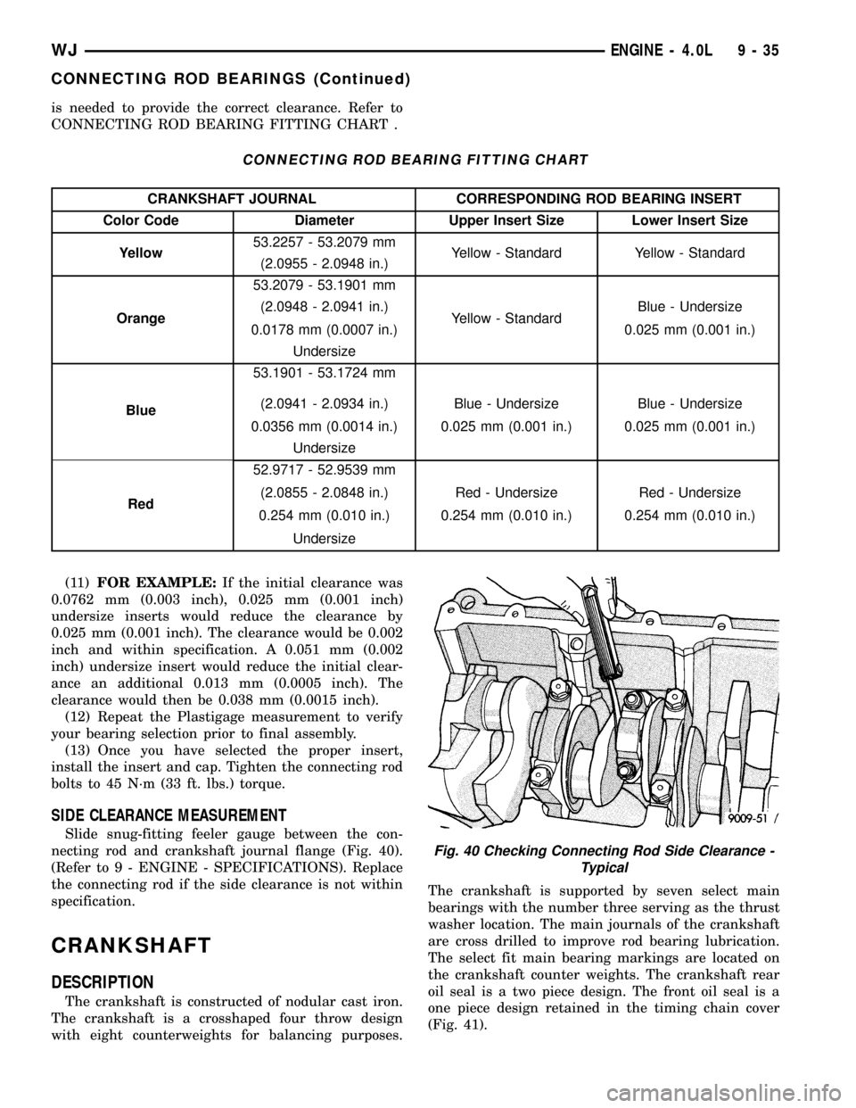
Slide snug-fitting feeler gauge between the con-
necting rod and crankshaft journal flange (Fig. 40).
(Refer to 9 - ENGINE - SPECIFICATIONS). Replace
the connecting rod if the side clearance is not within
specification.
CRANKSHAFT
DESCRIPTION
The crankshaft is constructed of nodular cast iron.
The crankshaft is a crosshaped four throw design
with eight counterweights for balancing purposes.The crankshaft is supported by seven select main
bearings with the number three serving as the thrust
washer location. The main journals of the crankshaft
are cross drilled to improve rod bearing lubrication.
The select fit main bearing markings are located on
the crankshaft counter weights. The crankshaft rear
oil seal is a two piece design. The front oil seal is a
one piece design retained in the timing chain cover
(Fig. 41).
Fig. 40 Checking Connecting Rod Side Clearance -
Typical
WJENGINE - 4.0L 9 - 35
CONNECTING ROD BEARINGS (Continued)
Page 1282 of 2199
REMOVAL
(1) Disconnect negative cable from battery.
(2) Remove the spark plugs (Refer to 8 - ELEC-
TRICAL/IGNITION CONTROL/SPARK PLUG -
REMOVAL).
(3) Raise the vehicle.
(4) Remove the oil pan (Refer to 9 - ENGINE/LU-
BRICATION/OIL PAN - REMOVAL) and oil pump
(Refer to 9 - ENGINE/LUBRICATION/OIL PUMP -
REMOVAL).
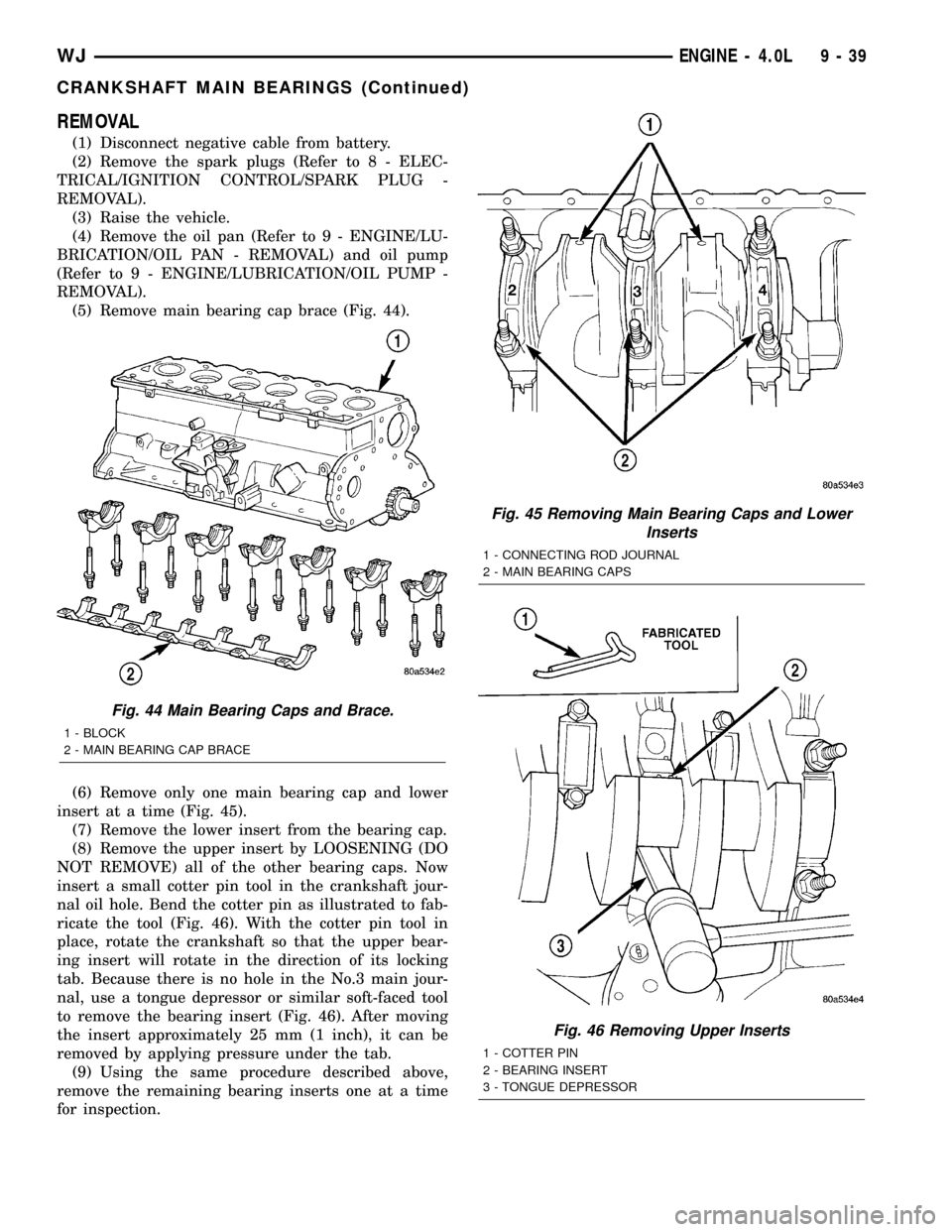
(5) Remove main bearing cap brace (Fig. 44).
(6) Remove only one main bearing cap and lower
insert at a time (Fig. 45).
(7) Remove the lower insert from the bearing cap.
(8) Remove the upper insert by LOOSENING (DO
NOT REMOVE) all of the other bearing caps. Now
insert a small cotter pin tool in the crankshaft jour-
nal oil hole. Bend the cotter pin as illustrated to fab-
ricate the tool (Fig. 46). With the cotter pin tool in
place, rotate the crankshaft so that the upper bear-
ing insert will rotate in the direction of its locking
tab. Because there is no hole in the No.3 main jour-
nal, use a tongue depressor or similar soft-faced tool
to remove the bearing insert (Fig. 46). After moving
the insert approximately 25 mm (1 inch), it can be
removed by applying pressure under the tab.
(9) Using the same procedure described above,
remove the remaining bearing inserts one at a time
for inspection.
Fig. 44 Main Bearing Caps and Brace.
1 - BLOCK
2 - MAIN BEARING CAP BRACE
Fig. 45 Removing Main Bearing Caps and Lower
Inserts
1 - CONNECTING ROD JOURNAL
2 - MAIN BEARING CAPS
Fig. 46 Removing Upper Inserts
1 - COTTER PIN
2 - BEARING INSERT
3 - TONGUE DEPRESSOR
WJENGINE - 4.0L 9 - 39
CRANKSHAFT MAIN BEARINGS (Continued)
Page 1296 of 2199
(5) If the leak is not detected, very slowly turn the
crankshaft and watch for leakage. If a leak is
detected between the crankshaft and seal while
slowly turning the crankshaft, it is possible the
crankshaft seal surface is damaged. The seal area on
the crankshaft could have minor nicks or scratches
that can be polished out with emery cloth.
CAUTION: Use extreme caution when crankshaft
polishing is necessary to remove minor nicks and
scratches. The crankshaft seal flange is especially
machined to complement the function of the rear oil
seal.
(6) For bubbles that remain steady with shaft
rotation, no further inspection can be done until dis-
assembled.
OIL
STANDARD PROCEDURE - ENGINE OIL
SERVICE
ENGINE OIL CHANGE
Change engine oil at mileage and time intervals
described in Maintenance Schedules.
Run engine until achieving normal operating tem-
perature.
(1) Position the vehicle on a level surface and turn
engine off.
(2) Hoist and support vehicle on safety stands.
(3) Remove oil fill cap.
(4) Place a suitable drain pan under crankcase
drain.
(5) Remove drain plug from crankcase and allow
oil to drain into pan. Inspect drain plug threads for
stretching or other damage. Replace drain plug if
damaged.
(6) Install drain plug in crankcase.
(7) Replace engine oil filter. (Refer to 9 - ENGINE/
LUBRICATION/OIL FILTER - REMOVAL).
(8) Lower vehicle and fill crankcase with specified
type of engine oil (Refer to LUBRICATION & MAIN-
TENANCE/FLUID TYPES - DESCRIPTION) and
amount of engine oil (Refer to LUBRICATION &
MAINTENANCE - SPECIFICATIONS).
(9) Install oil fill cap.
(10) Start engine and inspect for leaks.
(11) Stop engine and inspect oil level. Refer to
CRANKCASE OIL LEVEL INSPECTION .
USED ENGINE OIL DISPOSAL
Care should be exercised when disposing used
engine oil after it has been drained from a vehicle
engine.
CRANKCASE OIL LEVEL INSPECTION
CAUTION: Do not overfill crankcase with engine oil,
oil foaming and oil pressure loss can result.
The engine oil level indicator (Dipstick) is located
at the right rear of the 4.0L engine. Inspect engine
oil level approximately every 800 kilometers (500
miles). Unless the engine has exhibited loss of oil
pressure, run the engine for about five minutes
before checking oil level. Checking engine oil level on
a cold engine is not accurate.
To ensure proper lubrication of an engine, the
engine oil must be maintained at an acceptable level.
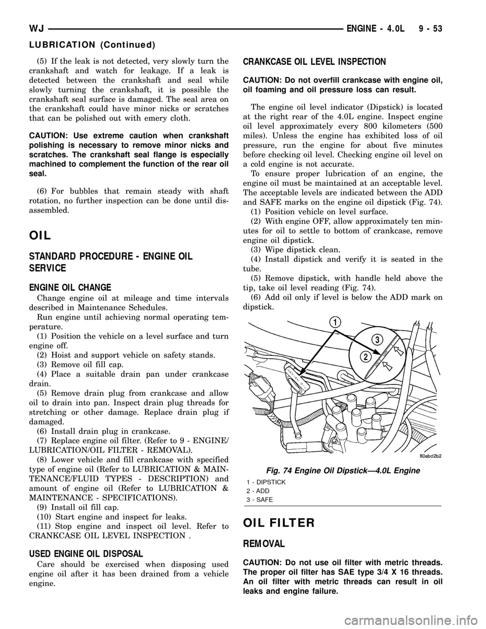
The acceptable levels are indicated between the ADD
and SAFE marks on the engine oil dipstick (Fig. 74).
(1) Position vehicle on level surface.
(2) With engine OFF, allow approximately ten min-
utes for oil to settle to bottom of crankcase, remove
engine oil dipstick.
(3) Wipe dipstick clean.
(4) Install dipstick and verify it is seated in the
tube.
(5) Remove dipstick, with handle held above the
tip, take oil level reading (Fig. 74).
(6) Add oil only if level is below the ADD mark on
dipstick.
OIL FILTER
REMOVAL
CAUTION: Do not use oil filter with metric threads.
The proper oil filter has SAE type 3/4 X 16 threads.
An oil filter with metric threads can result in oil
leaks and engine failure.
Fig. 74 Engine Oil DipstickÐ4.0L Engine
1 - DIPSTICK
2 - ADD
3 - SAFE
WJENGINE - 4.0L 9 - 53
LUBRICATION (Continued)
Page 1307 of 2199
DIAGNOSIS AND TESTING
DIAGNOSIS AND TESTING - ENGINE
DIAGNOSIS - INTRODUCTION
Engine diagnosis is helpful in determining the
causes of malfunctions not detected and remedied by
routine maintenance.
These malfunctions may be classified as either per-
formance (e.g., engine idles rough and stalls) or
mechanical (e.g., a strange noise).
(Refer to 9 - ENGINE - DIAGNOSIS AND TEST-
ING)ÐPERFORMANCE and (Refer to 9 - ENGINE -
DIAGNOSIS AND TESTING)ÐMECHANICAL for
possible causes and corrections of malfunctions.
(Refer to 14 - FUEL SYSTEM/FUEL DELIVERY -
DIAGNOSIS AND TESTING) and (Refer to 14 -
FUEL SYSTEM/FUEL INJECTION - DIAGNOSIS
AND TESTING) for the fuel system diagnosis.
Additional tests and diagnostic procedures may be
necessary for specific engine malfunctions that can
not be isolated with the Service Diagnosis charts.
Information concerning additional tests and diagno-
sis is provided within the following diagnosis:
²Cylinder Compression Pressure Test (Refer to 9 -
ENGINE - DIAGNOSIS AND TESTING).
²Cylinder Combustion Pressure Leakage Test
(Refer to 9 - ENGINE - DIAGNOSIS AND TEST-
ING).
²Engine Cylinder Head Gasket Failure Diagnosis
(Refer to 9 - ENGINE/CYLINDER HEAD - DIAGNO-
SIS AND TESTING).
²Intake Manifold Leakage Diagnosis (Refer to 9 -
ENGINE/MANIFOLDS/INTAKE MANIFOLD -
DIAGNOSIS AND TESTING).
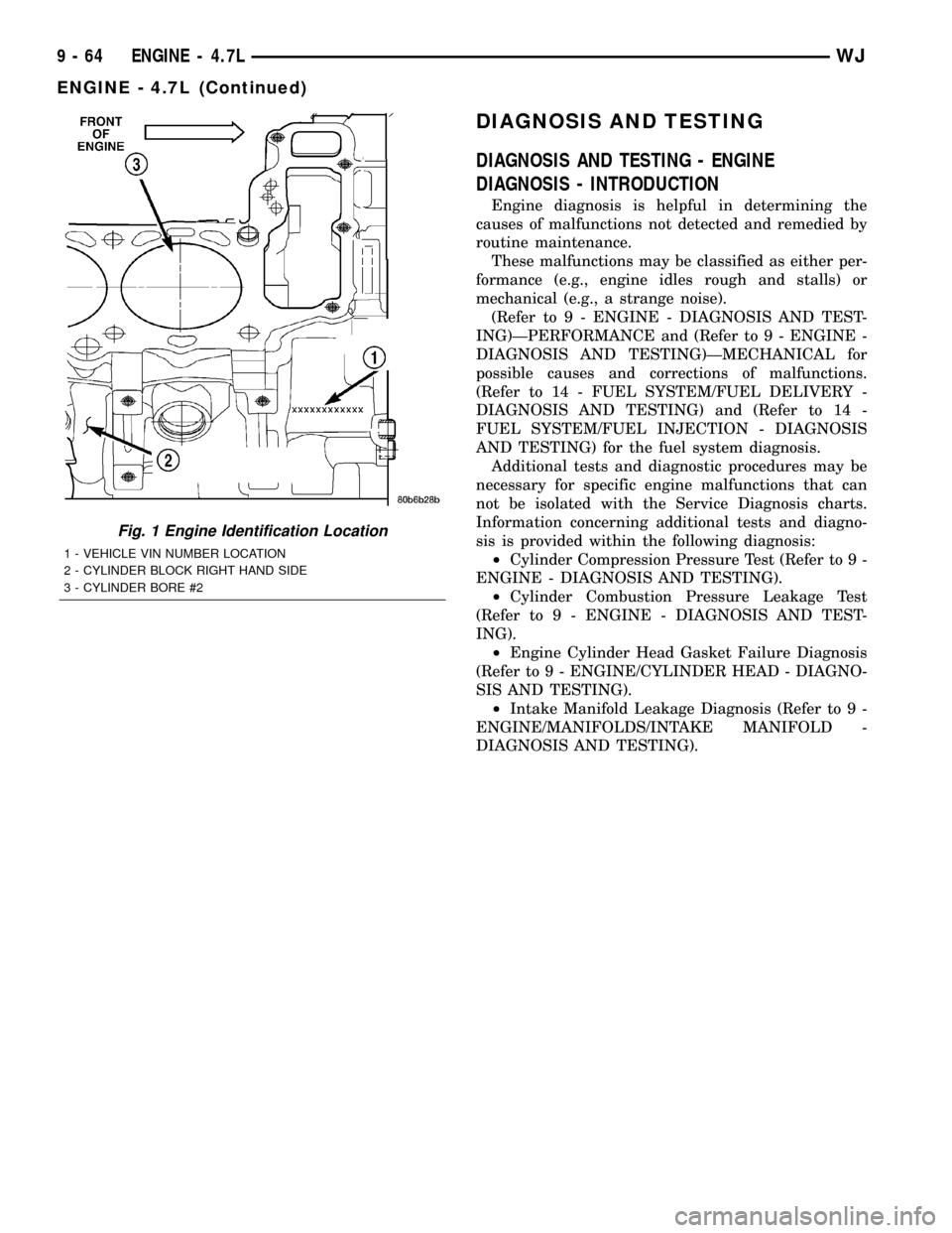
Fig. 1 Engine Identification Location
1 - VEHICLE VIN NUMBER LOCATION
2 - CYLINDER BLOCK RIGHT HAND SIDE
3 - CYLINDER BORE #2
9 - 64 ENGINE - 4.7LWJ
ENGINE - 4.7L (Continued)
Page 1329 of 2199
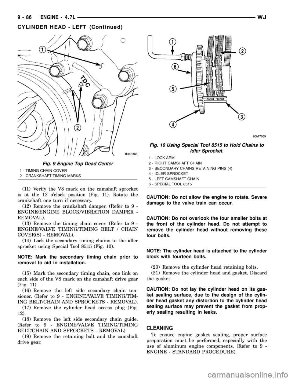
(11) Verify the V8 mark on the camshaft sprocket
is at the 12 o'clock position (Fig. 11). Rotate the
crankshaft one turn if necessary.
(12) Remove the crankshaft damper. (Refer to 9 -
ENGINE/ENGINE BLOCK/VIBRATION DAMPER -
REMOVAL).
(13) Remove the timing chain cover. (Refer to 9 -
ENGINE/VALVE TIMING/TIMING BELT / CHAIN
COVER(S) - REMOVAL).
(14) Lock the secondary timing chains to the idler
sprocket using Special Tool 8515 (Fig. 10).
NOTE: Mark the secondary timing chain prior to
removal to aid in installation.
(15) Mark the secondary timing chain, one link on
each side of the V8 mark on the camshaft drive gear
(Fig. 11).
(16) Remove the left side secondary chain ten-
sioner. (Refer to 9 - ENGINE/VALVE TIMING/TIM-
ING BELT/CHAIN AND SPROCKETS - REMOVAL).
(17) Remove the cylinder head access plug (Fig.
12).
(18) Remove the left side secondary chain guide.
(Refer to 9 - ENGINE/VALVE TIMING/TIMING
BELT/CHAIN AND SPROCKETS - REMOVAL).
(19) Remove the retaining bolt and the camshaft
drive gear.CAUTION: Do not allow the engine to rotate. Severe
damage to the valve train can occur.
CAUTION: Do not overlook the four smaller bolts at
the front of the cylinder head. Do not attempt to
remove the cylinder head without removing these
four bolts.
NOTE: The cylinder head is attached to the cylinder
block with fourteen bolts.
(20) Remove the cylinder head retaining bolts.
(21) Remove the cylinder head and gasket. Discard
the gasket.
CAUTION: Do not lay the cylinder head on its gas-
ket sealing surface, due to the design of the cylin-
der head gasket any distortion to the cylinder head
sealing surface may prevent the gasket from prop-
erly sealing resulting in leaks.
CLEANING
To ensure engine gasket sealing, proper surface
preparation must be performed, especially with the
use of aluminum engine components. (Refer to 9 -
ENGINE - STANDARD PROCEDURE)
Fig. 9 Engine Top Dead Center
1 - TIMING CHAIN COVER
2 - CRANKSHAFT TIMING MARKS
Fig. 10 Using Special Tool 8515 to Hold Chains to
Idler Sprocket.
1 - LOCK ARM
2 - RIGHT CAMSHAFT CHAIN
3 - SECONDARY CHAINS RETAINING PINS (4)
4 - IDLER SPROCKET
5 - LEFT CAMSHAFT CHAIN
6 - SPECIAL TOOL 8515
9 - 86 ENGINE - 4.7LWJ
CYLINDER HEAD - LEFT (Continued)
Page 1332 of 2199
REMOVAL
CAUTION: When the timing chain is removed and
the cylinder heads are still installed, DO NOT force-
fully rotate the camshafts or crankshaft indepen-
dently of each other. Severe valve and/or piston
damage can occur.
CAUTION: When removing the cam sprocket, timing
chains or camshaft, Failure to use Special Tool
8350 will result in hydraulic tensioner ratchet over
extension, requiring timing chain cover removal to
reset the tensioner ratchet.
(1) Remove cylinder head cover (Refer to 9 -
ENGINE/CYLINDER HEAD/CYLINDER HEAD
COVER(S) - REMOVAL).
(2) Set engine to TDC cylinder #1, camshaft
sprocket V8 marks at the 12 o'clock position.
(3) Mark one link on the secondary timing chain
on both sides of the V8 mark on the camshaft
sprocket to aid in installation.
CAUTION: Do not hold or pry on the camshaft tar-
get wheel (Located on the right side camshaft
sprocket) for any reason, Severe damage will occur
to the target wheel resulting in a vehicle no start
condition.(4) Loosen butDO NOTremove the camshaft
sprocket retaining bolt. Leave the bolt snug against
the sprocket.
NOTE: The timing chain tensioners must be
secured prior to removing the camshaft sprockets.
Failure to secure tensioners will allow the tension-
ers to extend, requiring timing chain cover removal
in order to reset tensioners.
CAUTION: Do not force wedge past the narrowest
point between the chain strands. Damage to the
tensioners may occur.
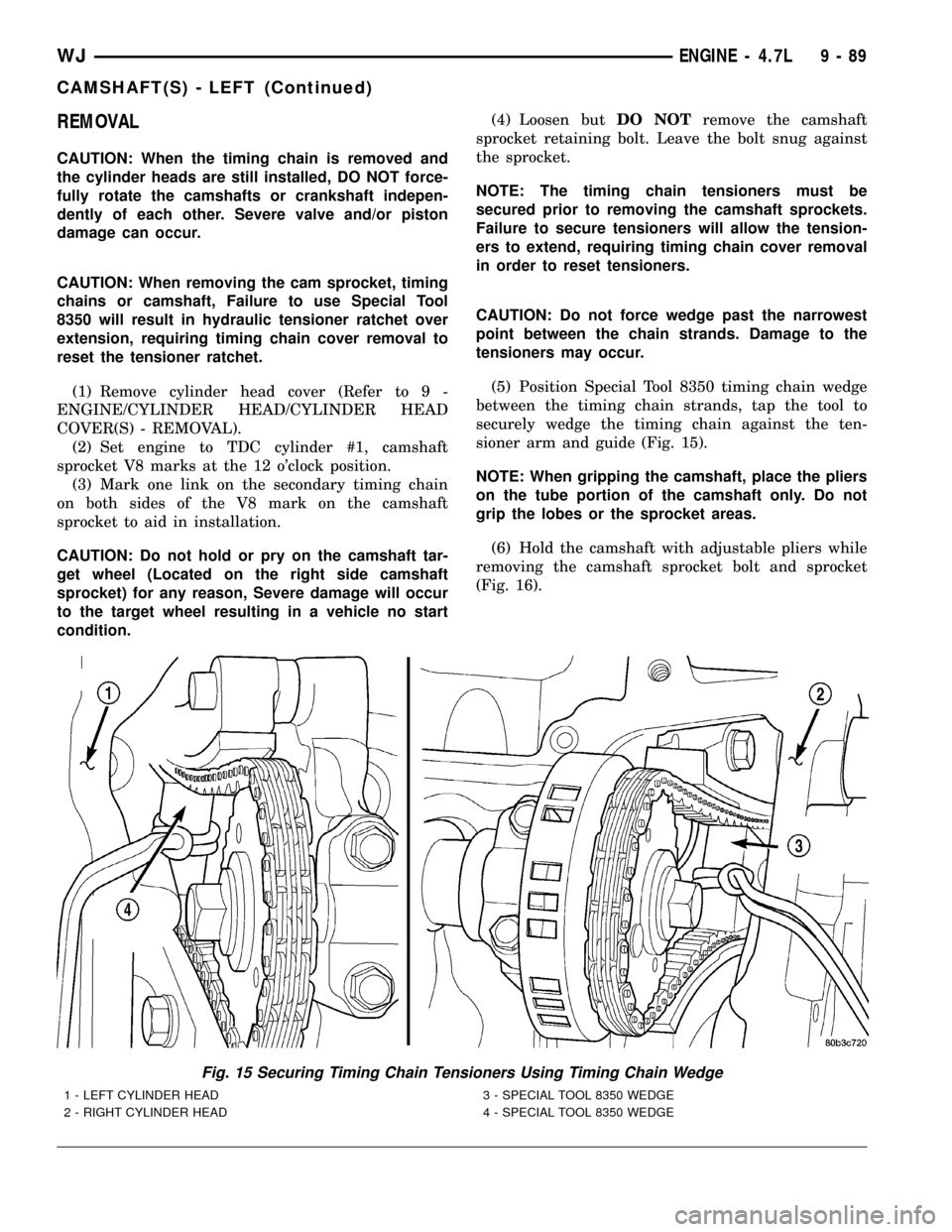
(5) Position Special Tool 8350 timing chain wedge
between the timing chain strands, tap the tool to
securely wedge the timing chain against the ten-
sioner arm and guide (Fig. 15).
NOTE: When gripping the camshaft, place the pliers
on the tube portion of the camshaft only. Do not
grip the lobes or the sprocket areas.
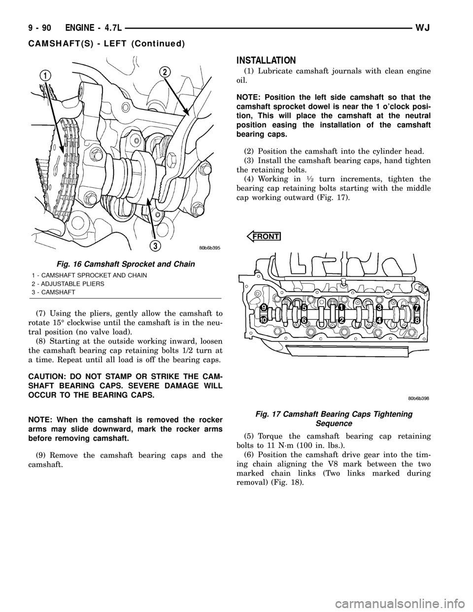
(6) Hold the camshaft with adjustable pliers while
removing the camshaft sprocket bolt and sprocket
(Fig. 16).
Fig. 15 Securing Timing Chain Tensioners Using Timing Chain Wedge
1 - LEFT CYLINDER HEAD
2 - RIGHT CYLINDER HEAD3 - SPECIAL TOOL 8350 WEDGE
4 - SPECIAL TOOL 8350 WEDGE
WJENGINE - 4.7L 9 - 89
CAMSHAFT(S) - LEFT (Continued)
Page 1333 of 2199
(7) Using the pliers, gently allow the camshaft to
rotate 15É clockwise until the camshaft is in the neu-
tral position (no valve load).
(8) Starting at the outside working inward, loosen
the camshaft bearing cap retaining bolts 1/2 turn at
a time. Repeat until all load is off the bearing caps.
CAUTION: DO NOT STAMP OR STRIKE THE CAM-
SHAFT BEARING CAPS. SEVERE DAMAGE WILL
OCCUR TO THE BEARING CAPS.
NOTE: When the camshaft is removed the rocker
arms may slide downward, mark the rocker arms
before removing camshaft.
(9) Remove the camshaft bearing caps and the
camshaft.
INSTALLATION
(1) Lubricate camshaft journals with clean engine
oil.
NOTE: Position the left side camshaft so that the
camshaft sprocket dowel is near the 1 o'clock posi-
tion, This will place the camshaft at the neutral
position easing the installation of the camshaft
bearing caps.
(2) Position the camshaft into the cylinder head.
(3) Install the camshaft bearing caps, hand tighten
the retaining bolts.
(4) Working in
1¤2turn increments, tighten the
bearing cap retaining bolts starting with the middle
cap working outward (Fig. 17).
(5) Torque the camshaft bearing cap retaining
bolts to 11 N´m (100 in. lbs.).
(6) Position the camshaft drive gear into the tim-
ing chain aligning the V8 mark between the two
marked chain links (Two links marked during
removal) (Fig. 18).
Fig. 16 Camshaft Sprocket and Chain
1 - CAMSHAFT SPROCKET AND CHAIN
2 - ADJUSTABLE PLIERS
3 - CAMSHAFT
Fig. 17 Camshaft Bearing Caps Tightening
Sequence
9 - 90 ENGINE - 4.7LWJ
CAMSHAFT(S) - LEFT (Continued)
Page 1338 of 2199
NOTE: All eight valve springs and valves are
removed in the same manner; this procedure only
covers one valve and valve spring.
(3) Using Special Tool C-3422±B or C-3422±C
Valve Spring Compressor and Special tool 8519
Adapter, compress the valve spring.
NOTE: It may be necessary to tap the top of the
valve spring to loosen the spring retainers locks
enough to be removed.
(4) Remove the two spring retainer lock halves.
NOTE: the valve spring is under tension use care
when releasing the valve spring compressor.
(5) Remove the valve spring compressor.
(6) Remove the spring retainer, and the spring.
NOTE: Check for sharp edges on the keeper
grooves. Remove any burrs from the valve stem
before removing the valve from the cylinder head.
(7) Remove the valve from the cylinder head.
NOTE: The valve stem seals are common between
intake and exhaust.
(8) Remove the valve stem seal. Mark the valve for
proper installation.
TESTING VALVE SPRINGS
NOTE: Whenever the valves are removed from the
cylinder head it is recommended that the valve
springs be inspected and tested for reuse.
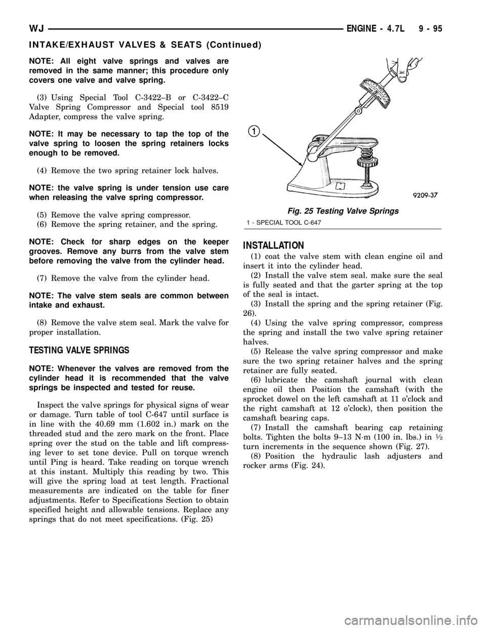
Inspect the valve springs for physical signs of wear
or damage. Turn table of tool C-647 until surface is
in line with the 40.69 mm (1.602 in.) mark on the
threaded stud and the zero mark on the front. Place
spring over the stud on the table and lift compress-
ing lever to set tone device. Pull on torque wrench
until Ping is heard. Take reading on torque wrench
at this instant. Multiply this reading by two. This
will give the spring load at test length. Fractional
measurements are indicated on the table for finer
adjustments. Refer to Specifications Section to obtain
specified height and allowable tensions. Replace any
springs that do not meet specifications. (Fig. 25)
INSTALLATION
(1) coat the valve stem with clean engine oil and
insert it into the cylinder head.
(2) Install the valve stem seal. make sure the seal
is fully seated and that the garter spring at the top
of the seal is intact.
(3) Install the spring and the spring retainer (Fig.
26).
(4) Using the valve spring compressor, compress
the spring and install the two valve spring retainer
halves.
(5) Release the valve spring compressor and make
sure the two spring retainer halves and the spring
retainer are fully seated.
(6) lubricate the camshaft journal with clean
engine oil then Position the camshaft (with the
sprocket dowel on the left camshaft at 11 o'clock and
the right camshaft at 12 o'clock), then position the
camshaft bearing caps.
(7) Install the camshaft bearing cap retaining
bolts. Tighten the bolts 9±13 N´m (100 in. lbs.) in
1¤2
turn increments in the sequence shown (Fig. 27).
(8) Position the hydraulic lash adjusters and
rocker arms (Fig. 24).
Fig. 25 Testing Valve Springs
1 - SPECIAL TOOL C-647
WJENGINE - 4.7L 9 - 95
INTAKE/EXHAUST VALVES & SEATS (Continued)
Page 1342 of 2199
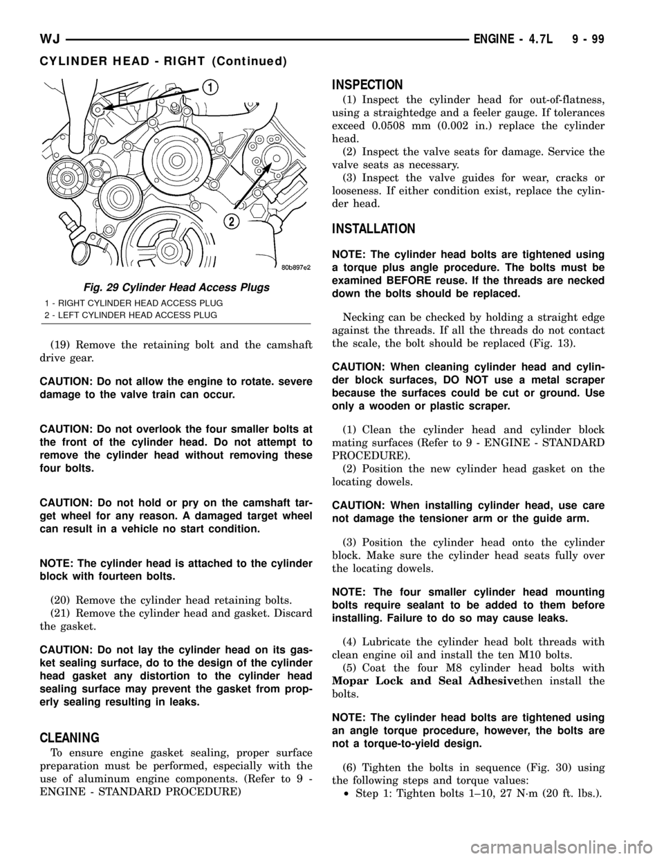
(19) Remove the retaining bolt and the camshaft
drive gear.
CAUTION: Do not allow the engine to rotate. severe
damage to the valve train can occur.
CAUTION: Do not overlook the four smaller bolts at
the front of the cylinder head. Do not attempt to
remove the cylinder head without removing these
four bolts.
CAUTION: Do not hold or pry on the camshaft tar-
get wheel for any reason. A damaged target wheel
can result in a vehicle no start condition.
NOTE: The cylinder head is attached to the cylinder
block with fourteen bolts.
(20) Remove the cylinder head retaining bolts.
(21) Remove the cylinder head and gasket. Discard
the gasket.
CAUTION: Do not lay the cylinder head on its gas-
ket sealing surface, do to the design of the cylinder
head gasket any distortion to the cylinder head
sealing surface may prevent the gasket from prop-
erly sealing resulting in leaks.
CLEANING
To ensure engine gasket sealing, proper surface
preparation must be performed, especially with the
use of aluminum engine components. (Refer to 9 -
ENGINE - STANDARD PROCEDURE)
INSPECTION
(1) Inspect the cylinder head for out-of-flatness,
using a straightedge and a feeler gauge. If tolerances
exceed 0.0508 mm (0.002 in.) replace the cylinder
head.
(2) Inspect the valve seats for damage. Service the
valve seats as necessary.
(3) Inspect the valve guides for wear, cracks or
looseness. If either condition exist, replace the cylin-
der head.
INSTALLATION
NOTE: The cylinder head bolts are tightened using
a torque plus angle procedure. The bolts must be
examined BEFORE reuse. If the threads are necked
down the bolts should be replaced.
Necking can be checked by holding a straight edge
against the threads. If all the threads do not contact
the scale, the bolt should be replaced (Fig. 13).
CAUTION: When cleaning cylinder head and cylin-
der block surfaces, DO NOT use a metal scraper
because the surfaces could be cut or ground. Use
only a wooden or plastic scraper.
(1) Clean the cylinder head and cylinder block
mating surfaces (Refer to 9 - ENGINE - STANDARD
PROCEDURE).
(2) Position the new cylinder head gasket on the
locating dowels.
CAUTION: When installing cylinder head, use care
not damage the tensioner arm or the guide arm.
(3) Position the cylinder head onto the cylinder
block. Make sure the cylinder head seats fully over
the locating dowels.
NOTE: The four smaller cylinder head mounting
bolts require sealant to be added to them before
installing. Failure to do so may cause leaks.
(4) Lubricate the cylinder head bolt threads with
clean engine oil and install the ten M10 bolts.
(5) Coat the four M8 cylinder head bolts with
Mopar Lock and Seal Adhesivethen install the
bolts.
NOTE: The cylinder head bolts are tightened using
an angle torque procedure, however, the bolts are
not a torque-to-yield design.
(6) Tighten the bolts in sequence (Fig. 30) using
the following steps and torque values:
²Step 1: Tighten bolts 1±10, 27 N´m (20 ft. lbs.).
Fig. 29 Cylinder Head Access Plugs
1 - RIGHT CYLINDER HEAD ACCESS PLUG
2 - LEFT CYLINDER HEAD ACCESS PLUG
WJENGINE - 4.7L 9 - 99
CYLINDER HEAD - RIGHT (Continued)
Page 1343 of 2199
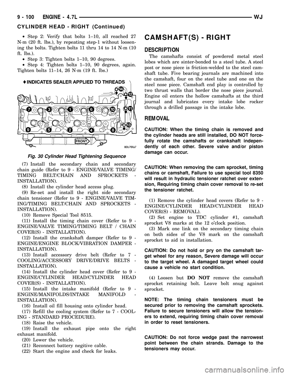
²Step 2: Verify that bolts 1±10, all reached 27
N´m (20 ft. lbs.), by repeating step-1 without loosen-
ing the bolts. Tighten bolts 11 thru 14 to 14 N´m (10
ft. lbs.).
²Step 3: Tighten bolts 1±10, 90 degrees.
²Step 4: Tighten bolts 1±10, 90 degrees, again.
Tighten bolts 11±14, 26 N´m (19 ft. lbs.)
(7) Install the secondary chain and secondary
chain guide (Refer to 9 - ENGINE/VALVE TIMING/
TIMING BELT/CHAIN AND SPROCKETS -
INSTALLATION).
(8) Install the cylinder head access plug.
(9) Re-set and install the right side secondary
chain tensioner (Refer to 9 - ENGINE/VALVE TIM-
ING/TIMING BELT/CHAIN AND SPROCKETS -
INSTALLATION).
(10) Remove Special Tool 8515.
(11) Install the timing chain cover (Refer to 9 -
ENGINE/VALVE TIMING/TIMING BELT / CHAIN
COVER(S) - INSTALLATION).
(12) Install the crankshaft damper (Refer to 9 -
ENGINE/ENGINE BLOCK/VIBRATION DAMPER -
INSTALLATION).
(13) Install accessory drive belt (Refer to 7 -
COOLING/ACCESSORY DRIVE/DRIVE BELTS -
INSTALLATION).
(14) Install the cylinder head cover (Refer to 9 -
ENGINE/CYLINDER HEAD/CYLINDER HEAD
COVER(S) - INSTALLATION).
(15) Install the intake manifold (Refer to 9 -
ENGINE/MANIFOLDS/INTAKE MANIFOLD -
INSTALLATION).
(16) Install oil fill housing onto cylinder head.
(17) Refill the cooling system (Refer to 7 - COOL-
ING - STANDARD PROCEDURE).
(18) Raise the vehicle.
(19) Install the exhaust pipe onto the right
exhaust manifold.
(20) Lower the vehicle.
(21) Reconnect battery negitive cable.
(22) Start the engine and check for leaks.CAMSHAFT(S) - RIGHT
DESCRIPTION
The camshafts consist of powdered metal steel
lobes which are sinter-bonded to a steel tube. A steel
post or nose piece is friction-welded to the steel cam-
shaft tube. Five bearing journals are machined into
the camshaft, four on the steel tube and one on the
steel nose piece. Camshaft end play is controlled by
two thrust walls that border the nose piece journal.
Engine oil enters the hollow camshafts at the third
journal and lubricates every intake lobe rocker
through a drilled passage in the intake lobe.
REMOVAL
CAUTION: When the timing chain is removed and
the cylinder heads are still installed, DO NOT force-
fully rotate the camshafts or crankshaft indepen-
dently of each other. Severe valve and/or piston
damage can occur.
CAUTION: When removing the cam sprocket, timing
chains or camshaft, Failure to use special tool 8350
will result in hydraulic tensioner ratchet over exten-
sion, Requiring timing chain cover removal to re-set
the tensioner ratchet.
(1) Remove the cylinder head covers (Refer to 9 -
ENGINE/CYLINDER HEAD/CYLINDER HEAD
COVER(S) - REMOVAL).
(2) Set engine to TDC cylinder #1, camshaft
sprocket V8 marks at the 12 o'clock position.
(3) Mark one link on the secondary timing chain
on both sides of the V8 mark on the camshaft
sprocket to aid in installation.
CAUTION: Do not hold or pry on the camshaft tar-
get wheel for any reason, Severe damage will occur
to the target wheel. A damaged target wheel could
cause a vehicle no start condition.
(4) Loosen butDO NOTremove the camshaft
sprocket retaining bolt. Leave bolt snug against
sprocket.
NOTE: The timing chain tensioners must be
secured prior to removing the camshaft sprockets.
Failure to secure tensioners will allow the tension-
ers to extend, requiring timing chain cover removal
in order to reset tensioners.
CAUTION: Do not force wedge past the narrowest
point between the chain strands. Damage to the
tensioners may occur.
Fig. 30 Cylinder Head Tightening Sequence
9 - 100 ENGINE - 4.7LWJ
CYLINDER HEAD - RIGHT (Continued)