Oil pan installation JEEP GRAND CHEROKEE 2002 WJ / 2.G User Guide
[x] Cancel search | Manufacturer: JEEP, Model Year: 2002, Model line: GRAND CHEROKEE, Model: JEEP GRAND CHEROKEE 2002 WJ / 2.GPages: 2199, PDF Size: 76.01 MB
Page 466 of 2199
INSTALLATION - BULB
CAUTION: Do not touch the bulb glass with fingers
or other oily surfaces. Reduced bulb life will result.
(1) Position the bulb into socket and push into
place.
(2) Position the bulb socket in headlamp and turn
the bulb socket one quarter turn clockwise.
(3) Install the headlamp.
HEADLAMP SWITCH
DESCRIPTION
The headlamp switch is part of the left multi-func-
tion switch. A knob on the end of the multi-function
switch control stalk controls all of the exterior light-
ing switch functions. The exterior lighting switch is
hard wired to the Body Control Module (BCM).
The exterior lighting switch cannot be adjusted or
repaired and, if faulty or damaged, the entire left
multi-function switch unit must be replaced. (Refer
to 8 - ELECTRICAL/LAMPS/LIGHTING - EXTERI-
OR/TURN SIGNAL/HAZARD SWITCH - REMOVAL)
for the service procedures. (Refer to 8 - ELECTRI-
CAL/ELECTRONIC CONTROL MODULES/BODY
CONTROL/CENTRAL TIMER MODUL - DESCRIP-
TION) for more information on this component.
OPERATION
The exterior lighting switch uses a hard wired five
volt reference circuit from the BCM, resistor multi-
plexing and a hard wired switch output circuit to
provide the BCM with a zero to five volt signal thatindicates the status of all of the exterior lighting
switch settings. The BCM then uses control outputs
to energize the headlamp and park lamp relays that
activate the exterior lighting circuits.
The BCM monitors the exterior lighting switch sta-
tus, then sends the proper switch status messages to
other modules over the Programmable Communica-
tions Interface (PCI) data bus network. The exterior
lighting switch status is also used by the BCM as an
input for chime warning system operation.
DIAGNOSIS AND TESTING Ð HEADLAMP
SWITCH
Before testing the headlamp switch, turn on the
exterior lighting and open the driver side front door.
If the exterior lamps of the vehicle operate, but there
is no chime warning issued with the driver side front
door open, (Refer to 8 - ELECTRICAL/LAMPS/
LIGHTING - INTERIOR/DOOR AJAR SWITCH -
DIAGNOSIS AND TESTING). If the exterior lamps
of the vehicle are inoperative, but the chime warning
is issued, (Refer to 8 - ELECTRICAL/LAMPS/LIGHT-
ING - EXTERIOR - DIAGNOSIS AND TESTING).
If the exterior lamps and the chime warning are
both inoperative, test the left multi-function switch.
(Refer to 8 - ELECTRICAL/LAMPS/LIGHTING -
EXTERIOR - DIAGNOSIS AND TESTING). If the
multi-function switch tests OK, proceed as follows.
The following tests will help to locate a short or open
in the hard wired circuits between the multi-function
switch and the Body Control Module (BCM). For
complete circuit diagrams, refer to the appropriate
wiring information.
WARNING: ON VEHICLES EQUIPPED WITH AIR-
BAGS, REFER TO ELECTRICAL, RESTRAINTS
BEFORE ATTEMPTING ANY STEERING WHEEL,
STEERING COLUMN, OR INSTRUMENT PANEL
COMPONENT DIAGNOSIS OR SERVICE. FAILURE
TO TAKE THE PROPER PRECAUTIONS COULD
RESULT IN ACCIDENTAL AIRBAG DEPLOYMENT
AND POSSIBLE PERSONAL INJURY.
(1) Disconnect and isolate the battery negative
cable. Disconnect the instrument panel wire harness
connector from the left multi-function switch connec-
tor. Disconnect the instrument panel wire harness
connector from the Body Control Module (BCM).
Check for continuity between the headlamp switch
mux circuit of the instrument panel wire harness
connector for the multi-function switch and a good
ground. There should be no continuity. If OK, go to
Step 2. If not OK, repair the shorted headlamp
switch mux circuit.
(2) Check for continuity between the headlamp
switch mux circuit of the instrument panel wire har-
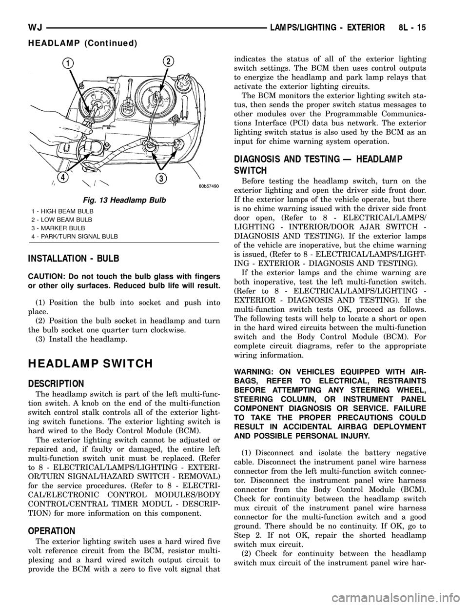
Fig. 13 Headlamp Bulb
1 - HIGH BEAM BULB
2 - LOW BEAM BULB
3 - MARKER BULB
4 - PARK/TURN SIGNAL BULB
WJLAMPS/LIGHTING - EXTERIOR 8L - 15
HEADLAMP (Continued)
Page 467 of 2199
ness connector for the multi-function switch and the
instrument panel wire harness connector for the
BCM. There should be continuity. If OK, go to Step 3.
If not OK, repair the open headlamp switch mux cir-
cuit.
(3) Check for continuity between the headlamp
switch return circuit of the instrument panel wire
harness connector for the multi-function switch and a
good ground. There should be no continuity. If OK, go
to Step 4. If not OK, repair the shorted headlamp
switch return circuit.
(4) Check for continuity between the headlamp
switch return circuit of the instrument panel wire
harness connector for the multi-function switch and
the instrument panel wire harness connector for the
BCM. There should be continuity. If OK, use a
DRBIIItscan tool and the proper Diagnostic Proce-
dures manual to test the BCM. If not OK, repair the
open headlamp switch return circuit.
HEADLAMP UNIT
REMOVAL
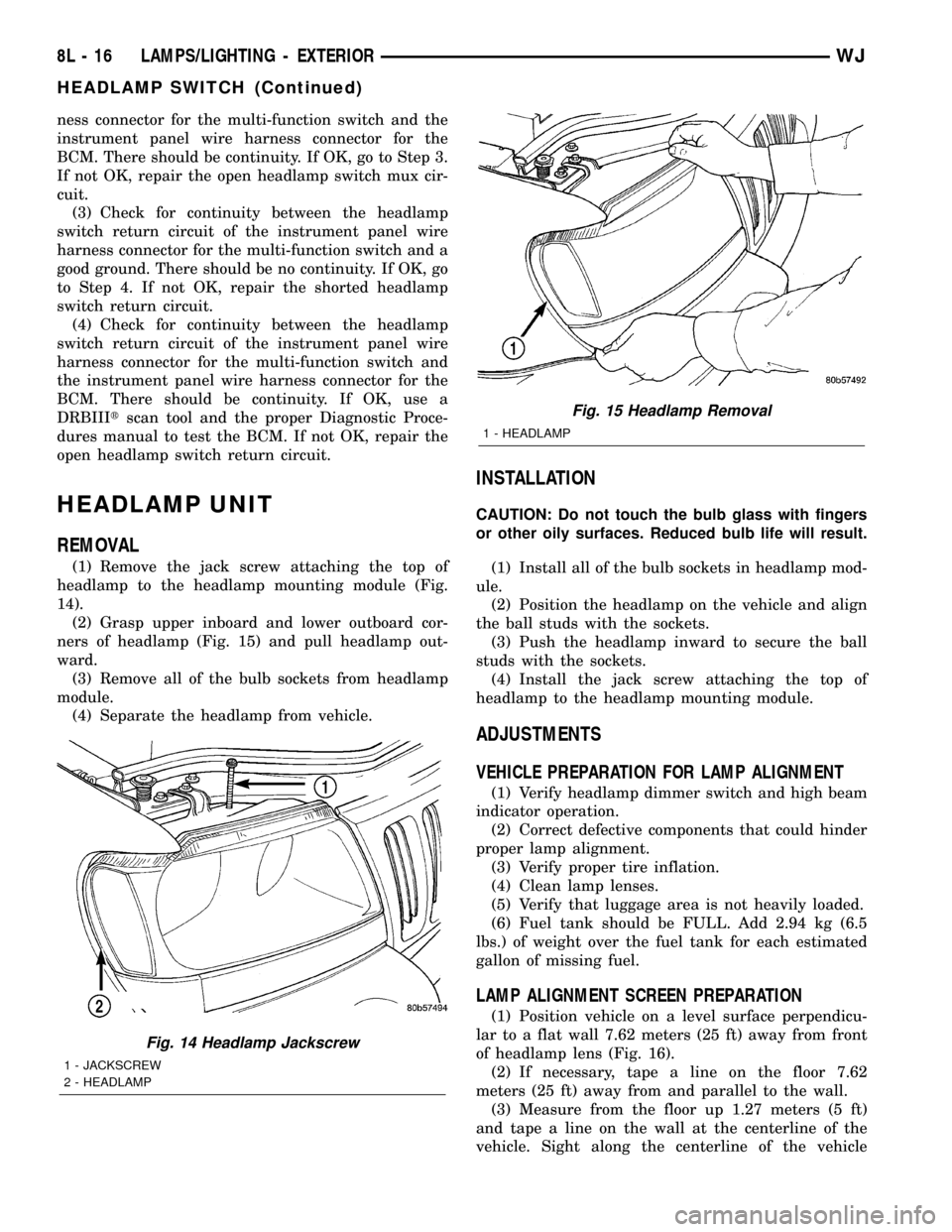
(1) Remove the jack screw attaching the top of
headlamp to the headlamp mounting module (Fig.
14).
(2) Grasp upper inboard and lower outboard cor-
ners of headlamp (Fig. 15) and pull headlamp out-
ward.
(3) Remove all of the bulb sockets from headlamp
module.
(4) Separate the headlamp from vehicle.
INSTALLATION
CAUTION: Do not touch the bulb glass with fingers
or other oily surfaces. Reduced bulb life will result.
(1) Install all of the bulb sockets in headlamp mod-
ule.
(2) Position the headlamp on the vehicle and align
the ball studs with the sockets.
(3) Push the headlamp inward to secure the ball
studs with the sockets.
(4) Install the jack screw attaching the top of
headlamp to the headlamp mounting module.
ADJUSTMENTS
VEHICLE PREPARATION FOR LAMP ALIGNMENT
(1) Verify headlamp dimmer switch and high beam
indicator operation.
(2) Correct defective components that could hinder
proper lamp alignment.
(3) Verify proper tire inflation.
(4) Clean lamp lenses.
(5) Verify that luggage area is not heavily loaded.
(6) Fuel tank should be FULL. Add 2.94 kg (6.5
lbs.) of weight over the fuel tank for each estimated
gallon of missing fuel.
LAMP ALIGNMENT SCREEN PREPARATION
(1) Position vehicle on a level surface perpendicu-
lar to a flat wall 7.62 meters (25 ft) away from front
of headlamp lens (Fig. 16).
(2) If necessary, tape a line on the floor 7.62
meters (25 ft) away from and parallel to the wall.
(3) Measure from the floor up 1.27 meters (5 ft)
and tape a line on the wall at the centerline of the
vehicle. Sight along the centerline of the vehicle
Fig. 14 Headlamp Jackscrew
1 - JACKSCREW
2 - HEADLAMP
Fig. 15 Headlamp Removal
1 - HEADLAMP
8L - 16 LAMPS/LIGHTING - EXTERIORWJ
HEADLAMP SWITCH (Continued)
Page 501 of 2199
the engine compartment. This relay can be energized
by the BCM to sound the horns as an audible alert
for the RKE panic function and, if the Sound Horn
on Lock programmable feature is enabled, as an
audible verification for the RKE lock event. (Refer to
8 - ELECTRICAL/HORN/HORN RELAY - DESCRIP-
TION).
LOW BEAM HEADLAMP RELAY
The low beam headlamp relay is a electromechan-
ical device that switches battery current to the head-
lamp low beams when the BCM grounds the relay
coil. The low beam headlamp relay is located in the
junction block in the passenger compartment. This
relay can be energized by the BCM to flash the head-
lamp low beams as an optical alert for the RKE panic
function. (Refer to 8 - ELECTRICAL/LAMPS/LIGHT-
ING - EXTERIOR/HEADLAMP - DESCRIPTION).
DESCRIPTION - LIFTGATE FLIP-UP GLASS
POWER RELEASE SYSTEM
A power operated liftgate flip-up glass release sys-
tem is standard factory installed equipment on this
model. The liftgate flip-up glass power release system
allows the flip-up glass latch to be released electri-
cally by depressing a switch located on the bottom of
the liftgate license plate lamp housing unit, above
the license plate on the outside of the liftgate.
The liftgate flip-up glass release system operates
on non-switched battery current supplied through a
fuse in the junction block so that the system remains
functional, regardless of the ignition switch position.
However, a limit switch that is integral to the liftgate
latch actuator unit opens to prevent the flip-up glass
latch from being actuated when the liftgate latch is
locked.
The liftgate flip-up glass power release system
includes the following components:
²Liftgate Flip-Up Glass Limit Switch- The
liftgate flip-up glass limit switch is integral to the
liftgate latch unit. (Refer to 23 - BODY/DECKLID/
HATCH/LIFTGATE/TAILGATE/LATCH - REMOVAL)
and (Refer to 23 - BODY/DECKLID/HATCH/LIFT-
GATE/TAILGATE/LATCH - INSTALLATION).
²Liftgate Flip-Up Glass Release Motor- The
liftgate flip-up glass release motor is integral to the
liftgate flip-up glass latch unit. (Refer to 23 - BODY/
DECKLID/HATCH/LIFTGATE/TAILGATE/FLIP-UP
GLASS LATCH - REMOVAL) and (Refer to 23 -
BODY/DECKLID/HATCH/LIFTGATE/TAILGATE/
FLIP-UP GLASS LATCH - INSTALLATION).
²Liftgate Flip-Up Glass Release Switch- The
liftgate flip-up glass release switch is integral to the
liftgate license plate lamp housing. (Refer to 23 -
BODY/DECKLID/HATCH/LIFTGATE/TAILGATE/
FLIP-UP GLASS SWITCH - REMOVAL) and (Referto 23 - BODY/DECKLID/HATCH/LIFTGATE/TAIL-
GATE/FLIP-UP GLASS SWITCH - INSTALLATION).
Hard wired circuitry connects the liftgate flip-up
glass power release system components to the electri-
cal system of the vehicle. These hard wired circuits
are integral to several wire harnesses, which are
routed throughout the vehicle and retained by many
different methods. These circuits may be connected to
each other, to the vehicle electrical system and to the
liftgate flip-up glass power release system compo-
nents through the use of a combination of soldered
splices, splice block connectors, and many different
types of wire harness terminal connectors and insu-
lators. Refer to the appropriate wiring information.
The wiring information includes wiring diagrams,
proper wire and connector repair procedures, further
details on wire harness routing and retention, as well
as pin-out and location views for the various wire
harness connectors, splices and grounds.OPERATION
OPERATION - POWER LOCK SYSTEM
The Passenger Door Module (PDM) contains the
power door lock control logic and a power lock switch.
The Driver Door Module (DDM) contains a power
lock switch and controls the output to the driver side
front door power lock motor, while the PDM controls
the output to the power lock motors for the remain-
ing doors and the liftgate.
When the power lock switch on the DDM is used to
lock or unlock the doors, the DDM sends a control
output to the driver side front door power lock motor
and sends lock or unlock request messages to the
PDM over the Programmable Communications Inter-
face (PCI) data bus. The PDM responds to these mes-
sages by sending control outputs to the power lock
motors of the remaining doors and the liftgate. When
the power lock switch on the PDM is used to lock or
unlock the doors, the PDM sends control outputs to
the power lock motors in the passenger side front
door, both rear doors and the liftgate, then sends lock
or unlock request messages to the DDM over the Pro-
grammable Communications Interface (PCI) data
bus. The DDM responds to these messages by send-
ing control outputs to the power lock motor of the
driver side front door.
In order to support the auto door locks and unlock
on exit features, if enabled, the power lock system
logic in the PDM needs to know the door ajar switch
status, vehicle speed, and transmission gear selector
lever position. The passenger side front door ajar
switch is the only hard wired input to the PDM. The
PDM obtains the remaining information from mes-
sages it receives from other electronic modules over
the PCI data bus network.
8N - 4 POWER LOCKSWJ
POWER LOCKS (Continued)
Page 1245 of 2199
REMOVAL
REMOVAL - CAMSHAFT BEARINGS.......31
REMOVAL - CAMSHAFT................31
INSPECTION
INSPECTION - CAMSHAFT BEARINGS.....31
INSPECTION - CAMSHAFT..............31
INSTALLATION
INSTALLATION - CAMSHAFT BEARINGS . . . 32
INSTALLATION - CAMSHAFT............32
CONNECTING ROD BEARINGS
STANDARD PROCEDURE - FITTING
CONNECTING ROD BEARINGS..........33
CRANKSHAFT
DESCRIPTION.........................35
CRANKSHAFT MAIN BEARINGS
STANDARD PROCEDURE - FITTING
CRANKSHAFT MAIN BEARINGS..........36
REMOVAL.............................39
INSPECTION..........................40
INSTALLATION.........................40
CRANKSHAFT OIL SEAL - FRONT
REMOVAL.............................41
INSTALLATION.........................41
CRANKSHAFT OIL SEAL - REAR
REMOVAL.............................42
INSTALLATION.........................42
HYDRAULIC LIFTERS
DESCRIPTION.........................43
REMOVAL.............................43
CLEANING............................43
INSPECTION..........................43
INSTALLATION.........................43
PISTON & CONNECTING ROD
DESCRIPTION.........................44
STANDARD PROCEDURE - PISTON FITTING . 44
REMOVAL.............................45
INSTALLATION.........................46
PISTON RINGS
STANDARD PROCEDURE - PISTON RING
FITTING.............................47
VIBRATION DAMPER
REMOVAL.............................49
INSTALLATION.........................49STRUCTURAL SUPPORT
REMOVAL.............................49
INSTALLATION.........................50
LUBRICATION
DESCRIPTION.........................50
OPERATION...........................50
DIAGNOSIS AND TESTING
DIAGNOSIS AND TESTING - ENGINE OIL
PRESSURE..........................51
DIAGNOSIS AND TESTING - ENGINE OIL
LEAK...............................51
OIL
STANDARD PROCEDURE - ENGINE OIL
SERVICE............................53
OIL FILTER
REMOVAL.............................53
INSTALLATION.........................54
OIL PAN
DESCRIPTION.........................54
REMOVAL.............................54
INSTALLATION.........................55
ENGINE OIL PRESSURE SENSOR
DESCRIPTION.........................56
OPERATION...........................56
OIL PUMP
REMOVAL.............................56
INSTALLATION.........................57
INTAKE MANIFOLD
DESCRIPTION.........................57
DIAGNOSIS AND TESTING - INTAKE
MANIFOLD LEAKAGE..................57
REMOVAL.............................57
INSTALLATION.........................57
EXHAUST MANIFOLD
DESCRIPTION.........................58
REMOVAL.............................58
INSTALLATION.........................58
TIMING BELT / CHAIN COVER(S)
REMOVAL.............................58
INSTALLATION.........................58
TIMING BELT/CHAIN AND SPROCKETS
REMOVAL.............................60
INSTALLATION.........................60
ENGINE - 4.0L
DESCRIPTION
The 4.0 Liter (242 CID) six-cylinder engine is an
In-line, lightweight, overhead valve engine. This
engine is designed for unleaded fuel.
The engine cylinder head has dual quench-type
combustion chambers that create turbulence and fast
burning of the air/fuel mixture. This results in better
fuel economy.
The cylinders are numbered 1 through 6 from front
to rear. The firing order is 1-5-3-6-2-4 (Fig. 1).The crankshaft rotation is clockwise, when viewed
from the front of the engine. The crankshaft rotates
within seven main bearings. The camshaft rotates
within four bearings.
The engine Build Date Code is located on a
machined surface on the right side of the cylinder
block between the No.2 and No.3 cylinders (Fig. 2).
The digits of the code identify:
²1st DigitÐThe year (8 = 1998).
²2nd & 3rd DigitsÐThe month (01 - 12).
²4th & 5th DigitsÐThe engine type/fuel system/
compression ratio (MX = A 4.0 Liter (242 CID) 8.7:1
compression ratio engine with a multi-point fuel
injection system).
9 - 2 ENGINE - 4.0LWJ
Page 1254 of 2199
CAUTION: DO NOT use engine or transmission oil,
mineral spirits, or kerosene.
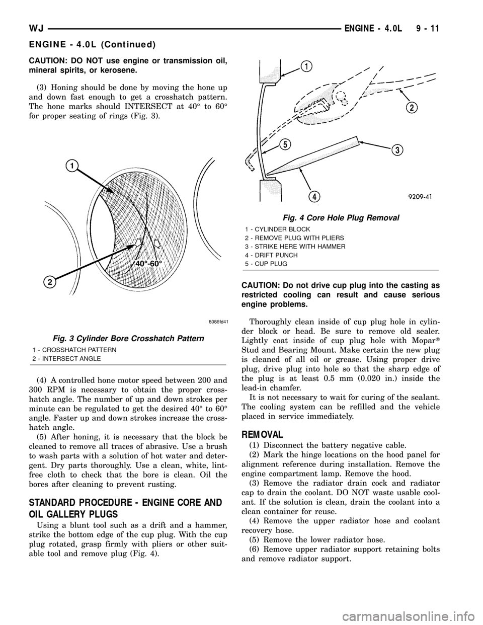
(3) Honing should be done by moving the hone up
and down fast enough to get a crosshatch pattern.
The hone marks should INTERSECT at 40É to 60É
for proper seating of rings (Fig. 3).
(4) A controlled hone motor speed between 200 and
300 RPM is necessary to obtain the proper cross-
hatch angle. The number of up and down strokes per
minute can be regulated to get the desired 40É to 60É
angle. Faster up and down strokes increase the cross-
hatch angle.
(5) After honing, it is necessary that the block be
cleaned to remove all traces of abrasive. Use a brush
to wash parts with a solution of hot water and deter-
gent. Dry parts thoroughly. Use a clean, white, lint-
free cloth to check that the bore is clean. Oil the
bores after cleaning to prevent rusting.
STANDARD PROCEDURE - ENGINE CORE AND
OIL GALLERY PLUGS
Using a blunt tool such as a drift and a hammer,
strike the bottom edge of the cup plug. With the cup
plug rotated, grasp firmly with pliers or other suit-
able tool and remove plug (Fig. 4).CAUTION: Do not drive cup plug into the casting as
restricted cooling can result and cause serious
engine problems.
Thoroughly clean inside of cup plug hole in cylin-
der block or head. Be sure to remove old sealer.
Lightly coat inside of cup plug hole with Mopart
Stud and Bearing Mount. Make certain the new plug
is cleaned of all oil or grease. Using proper drive
plug, drive plug into hole so that the sharp edge of
the plug is at least 0.5 mm (0.020 in.) inside the
lead-in chamfer.
It is not necessary to wait for curing of the sealant.
The cooling system can be refilled and the vehicle
placed in service immediately.
REMOVAL
(1) Disconnect the battery negative cable.
(2) Mark the hinge locations on the hood panel for
alignment reference during installation. Remove the
engine compartment lamp. Remove the hood.
(3) Remove the radiator drain cock and radiator
cap to drain the coolant. DO NOT waste usable cool-
ant. If the solution is clean, drain the coolant into a
clean container for reuse.
(4) Remove the upper radiator hose and coolant
recovery hose.
(5) Remove the lower radiator hose.
(6) Remove upper radiator support retaining bolts
and remove radiator support.
Fig. 3 Cylinder Bore Crosshatch Pattern
1 - CROSSHATCH PATTERN
2 - INTERSECT ANGLE
Fig. 4 Core Hole Plug Removal
1 - CYLINDER BLOCK
2 - REMOVE PLUG WITH PLIERS
3 - STRIKE HERE WITH HAMMER
4 - DRIFT PUNCH
5 - CUP PLUG
WJENGINE - 4.0L 9 - 11
ENGINE - 4.0L (Continued)
Page 1284 of 2199
(e) If end play is not within specification, inspect
crankshaft thrust faces for wear. If no wear is
apparent, replace the thrust bearing and measure
end play. If end play is still not within specifica-
tion, replace the crankshaft.
(11) If the crankshaft was removed, install the
crankshaft into the cylinder block.
(12) Install main bearing cap brace tighten nuts to
47 N´m (35 ft. lbs.) torque.
(13) Install oil pump assy. and tighten attaching
bolts to 23 N´m (17 ft. lbs.)
(14) Install the oil pan (Refer to 9 - ENGINE/LU-
BRICATION/OIL PAN - INSTALLATION).
(15) Install the drain plug. Tighten the plug to 34
N´m (25 ft. lbs.) torque.
(16) Lower the vehicle.
(17) Install the spark plugs. Tighten the plugs to
37 N´m (27 ft. lbs.) torque.
(18) Fill the oil pan with engine oil to the full
mark on the dipstick level.
(19) Connect negative cable to battery.
CRANKSHAFT OIL SEAL -
FRONT
REMOVAL
This procedure is done with the timing case cover
installed.
(1) Disconnect negative cable from battery.
(2) Remove the serpentine drive belt (Refer to 7 -
COOLING/ACCESSORY DRIVE/DRIVE BELTS -
REMOVAL).(3) Remove the vibration damper (Refer to 9 -
ENGINE/ENGINE BLOCK/VIBRATION DAMPER -
REMOVAL).
(4) Remove the radiator shroud.
(5) Carefully remove the oil seal. Make sure seal
bore is clean.
INSTALLATION
This procedure is done with the timing case cover
installed.
(1) Position the replacement oil seal on Timing
Case Cover Alignment and Seal Installation Tool
6139 with seal open end facing inward. Apply a light
film of Perfect Seal, or equivalent, on the outside
diameter of the seal. Lightly coat the crankshaft with
engine oil.
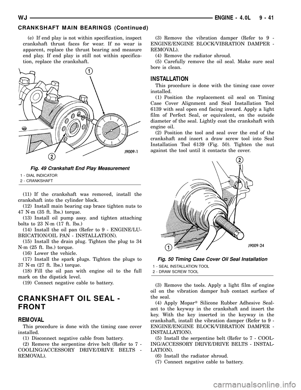
(2) Position the tool and seal over the end of the
crankshaft and insert a draw screw tool into Seal
Installation Tool 6139 (Fig. 50). Tighten the nut
against the tool until it contacts the cover.
(3) Remove the tools. Apply a light film of engine
oil on the vibration damper hub contact surface of
the seal.
(4) Apply MopartSilicone Rubber Adhesive Seal-
ant to the keyway in the crankshaft and insert the
key. With the key inserted in the keyway in the
crankshaft, install the vibration damper (Refer to 9 -
ENGINE/ENGINE BLOCK/VIBRATION DAMPER -
INSTALLATION).
(5) Install the serpentine belt (Refer to 7 - COOL-
ING/ACCESSORY DRIVE/DRIVE BELTS - INSTAL-
LATION).
(6) Install the radiator shroud.
(7) Connect negative cable to battery.
Fig. 49 Crankshaft End Play Measurement
1 - DIAL INDICATOR
2 - CRANKSHAFT
Fig. 50 Timing Case Cover Oil Seal Installation
1 - SEAL INSTALLATION TOOL
2 - DRAW SCREW TOOL
WJENGINE - 4.0L 9 - 41
CRANKSHAFT MAIN BEARINGS (Continued)
Page 1285 of 2199
CRANKSHAFT OIL SEAL -
REAR
REMOVAL
The crankshaft rear main bearing oil seal consists
of two half pieces of viton with a single lip that effec-
tively seals the rear of the crankshaft. Replace the
upper and lower seal halves as a unit to ensure leak-
free operation.
(1) Remove transmission inspection cover.
(2) Remove oil pan. (Refer to 9 - ENGINE/LUBRI-
CATION/OIL PAN - REMOVAL)
(3) Remove main bearing cap brace.
(4) Remove rear main bearing cap (No.7).
(5) Push upper seal out of the groove. Ensure that
the crankshaft and seal groove are not damaged.
(6) Remove lower half of the seal from the bearing
cap.
INSTALLATION
The crankshaft rear main bearing oil seal consists
of two half pieces of viton with a single lip that effec-
tively seals the rear of the crankshaft. Replace the
upper and lower seal halves as a unit to ensure leak-
free operation.
(1) Wipe the seal surface area of the crankshaft
until it is clean.
(2) Apply a thin coat of engine oil.
(3) Coat lip of the seal with engine oil.
(4) Carefully position the upper seal into the
groove in the cylinder block. The lip of the seal faces
toward the front of the engine.
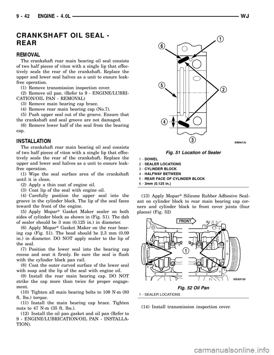
(5) Apply MopartGasket Maker sealer on both
sides of cylinder block as shown in (Fig. 51). The dab
of sealer should be 3 mm (0.125 in.) in diameter.
(6) Apply MopartGasket Maker on the rear bear-
ing cap (Fig. 51). The bead should be 2.3 mm (0.09
in.) in diameter. DO NOT apply sealer to the lip of
the seal.
(7) Position the lower seal into the bearing cap
recess and seat it firmly. Be sure the seal is flush
with the cylinder block pan rail.
(8) Coat the outer curved surface of the lower seal
with soap and the lip of the seal with engine oil.
(9) Install the rear main bearing cap. DO NOT
strike the cap more than twice for proper engage-
ment.
(10) Tighten all main bearing bolts to 108 N´m (80
ft. lbs.) torque.
(11) Install the main bearing cap brace. Tighten
nuts to 47 N´m (35 ft. lbs.).
(12) Install the oil pan gasket and oil pan (Refer to
9 - ENGINE/LUBRICATION/OIL PAN - INSTALLA-
TION).(13) Apply MopartSilicone Rubber Adhesive Seal-
ant on cylinder block to rear main bearing cap cor-
ners and cylinder block to front cover joints (four
places) (Fig. 52)
(14) Install transmission inspection cover.
Fig. 51 Location of Sealer
1-DOWEL
2-SEALER LOCATIONS
3-CYLINDER BLOCK
4-HALFWAY BETWEEN
5-REAR FACE OF CYLINDER BLOCK
6-3mm (0.125 in.)
Fig. 52 Oil Pan
1 - SEALER LOCATIONS
9 - 42 ENGINE - 4.0LWJ
Page 1290 of 2199
(12) Install the oil pan and gasket (Refer to 9 -
ENGINE/LUBRICATION/OIL PAN - INSTALLA-
TION).
(13) Lower the vehicle.
(14) Install the engine cylinder head (Refer to 9 -
ENGINE/CYLINDER HEAD - INSTALLATION),
push rods, rocker arms, bridges, pivots and engine
cylinder head cover(Refer to 9 - ENGINE/CYLINDER
HEAD/CYLINDER HEAD COVER(S) - INSTALLA-
TION).
(15) Fill the crankcase with engine oil.
PISTON RINGS
STANDARD PROCEDURE - PISTON RING
FITTING
(1) Carefully clean the carbon from all ring
grooves. Oil drain openings in the oil ring groove and
pin boss must be clear. DO NOT remove metal from
the grooves or lands. This will change ring-to-groove
clearances and will damage the ring-to-land seating.
(2) Be sure the piston ring grooves are free of
nicks and burrs.
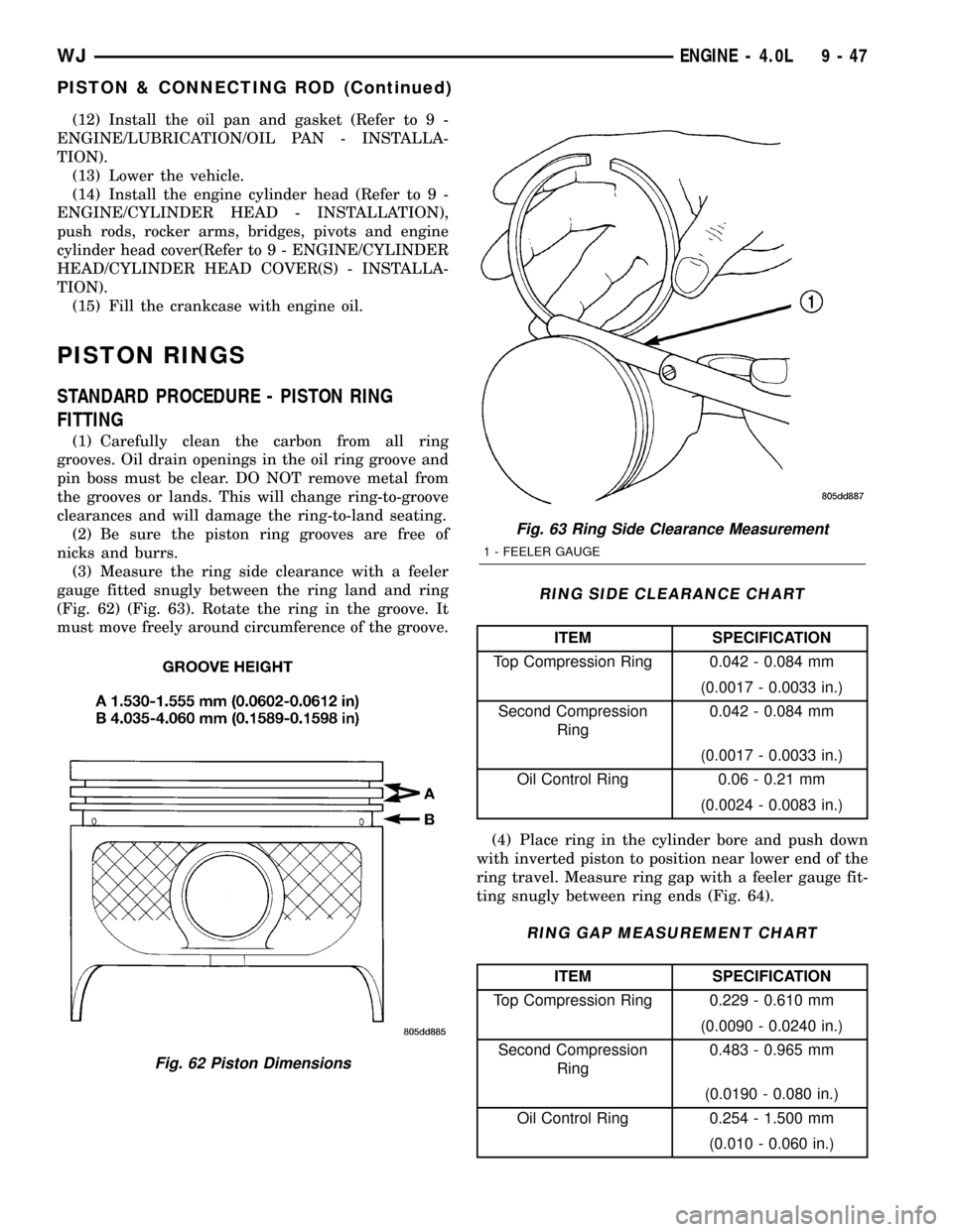
(3) Measure the ring side clearance with a feeler
gauge fitted snugly between the ring land and ring
(Fig. 62) (Fig. 63). Rotate the ring in the groove. It
must move freely around circumference of the groove.
RING SIDE CLEARANCE CHART
ITEM SPECIFICATION
Top Compression Ring 0.042 - 0.084 mm
(0.0017 - 0.0033 in.)
Second Compression
Ring0.042 - 0.084 mm
(0.0017 - 0.0033 in.)
Oil Control Ring 0.06 - 0.21 mm
(0.0024 - 0.0083 in.)
(4) Place ring in the cylinder bore and push down
with inverted piston to position near lower end of the
ring travel. Measure ring gap with a feeler gauge fit-
ting snugly between ring ends (Fig. 64).
RING GAP MEASUREMENT CHART
ITEM SPECIFICATION
Top Compression Ring 0.229 - 0.610 mm
(0.0090 - 0.0240 in.)
Second Compression
Ring0.483 - 0.965 mm
(0.0190 - 0.080 in.)
Oil Control Ring 0.254 - 1.500 mm
(0.010 - 0.060 in.)
Fig. 62 Piston Dimensions
Fig. 63 Ring Side Clearance Measurement
1 - FEELER GAUGE
WJENGINE - 4.0L 9 - 47
PISTON & CONNECTING ROD (Continued)
Page 1292 of 2199
VIBRATION DAMPER
REMOVAL
(1) Disconnect negative cable from battery.
(2) Remove the serpentine drive belt (Refer to 7 -
COOLING/ACCESSORY DRIVE/DRIVE BELTS -
REMOVAL) and fan shroud.
(3) Remove the vibration damper retaining bolt
and washer.
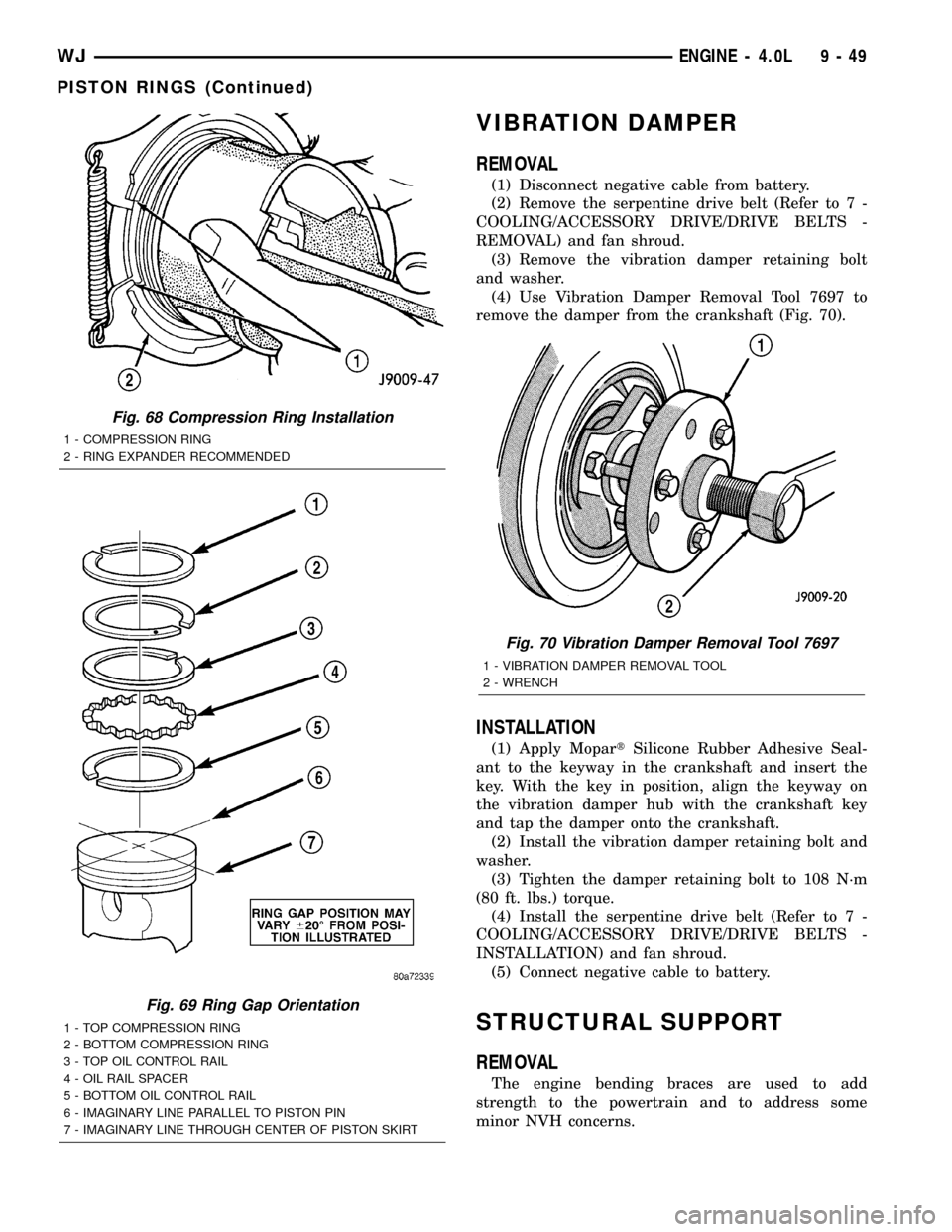
(4) Use Vibration Damper Removal Tool 7697 to
remove the damper from the crankshaft (Fig. 70).
INSTALLATION
(1) Apply MopartSilicone Rubber Adhesive Seal-
ant to the keyway in the crankshaft and insert the
key. With the key in position, align the keyway on
the vibration damper hub with the crankshaft key
and tap the damper onto the crankshaft.
(2) Install the vibration damper retaining bolt and
washer.
(3) Tighten the damper retaining bolt to 108 N´m
(80 ft. lbs.) torque.
(4) Install the serpentine drive belt (Refer to 7 -
COOLING/ACCESSORY DRIVE/DRIVE BELTS -
INSTALLATION) and fan shroud.
(5) Connect negative cable to battery.
STRUCTURAL SUPPORT
REMOVAL
The engine bending braces are used to add
strength to the powertrain and to address some
minor NVH concerns.
Fig. 68 Compression Ring Installation
1 - COMPRESSION RING
2 - RING EXPANDER RECOMMENDED
Fig. 69 Ring Gap Orientation
1 - TOP COMPRESSION RING
2 - BOTTOM COMPRESSION RING
3 - TOP OIL CONTROL RAIL
4 - OIL RAIL SPACER
5 - BOTTOM OIL CONTROL RAIL
6 - IMAGINARY LINE PARALLEL TO PISTON PIN
7 - IMAGINARY LINE THROUGH CENTER OF PISTON SKIRT
Fig. 70 Vibration Damper Removal Tool 7697
1 - VIBRATION DAMPER REMOVAL TOOL
2 - WRENCH
WJENGINE - 4.0L 9 - 49
PISTON RINGS (Continued)
Page 1293 of 2199
NOTE: Before the engine or the transmission can
be removed the engine bending braces must be
removed.
(1) Raise and support vehicle.
NOTE: Both left and right side bending braces are
removed the sameway. Only the right side is
shown.
NOTE: The exhaust does not require removal to
preform this procedure.
(2) Remove the exhaust hanger bracket retaining
bolt.
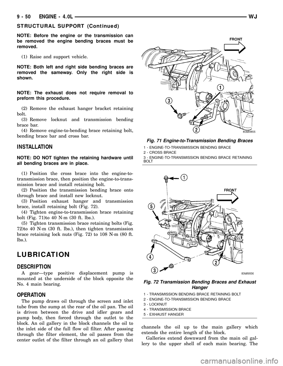
(3) Remove locknut and transmission bending
brace bar.
(4) Remove engine-to-bending brace retaining bolt,
bending brace bar and cross bar.
INSTALLATION
NOTE: DO NOT tighten the retaining hardware until
all bending braces are in place.
(1) Position the cross brace into the engine-to-
transmission brace, then position the engine-to-trans-
mission brace and install retaining bolt.
(2) Position the transmission bending brace onto
through brace and install new locknut.
(3) Position exhaust hanger and transmission
brace, install retaining bolt (Fig. 72).
(4) Tighten engine-to-transmission brace retaining
bolt (Fig. 71)to 40 N´m (30 ft. lbs.).
(5) Tighten transmission brace retaining bolts (Fig.
72)to 40 N´m (30 ft. lbs.), then tighten transmission
brace retaining lock nuts (Fig. 72) to 108 N´m (80 ft.
lbs.).
LUBRICATION
DESCRIPTION
A gearÐtype positive displacement pump is
mounted at the underside of the block opposite the
No. 4 main bearing.
OPERATION
The pump draws oil through the screen and inlet
tube from the sump at the rear of the oil pan. The oil
is driven between the drive and idler gears and
pump body, then forced through the outlet to the
block. An oil gallery in the block channels the oil to
the inlet side of the full flow oil filter. After passing
through the filter element, the oil passes from the
center outlet of the filter through an oil gallery thatchannels the oil up to the main gallery which
extends the entire length of the block.
Galleries extend downward from the main oil gal-
lery to the upper shell of each main bearing. The
Fig. 71 Engine-to-Transmission Bending Braces
1 - ENGINE-TO-TRANSMISSION BENDING BRACE
2 - CROSS BRACE
3 - ENGINE-TO-TRANSMISSION BENDING BRACE RETAINING
BOLT
Fig. 72 Transmission Bending Braces and Exhaust
Hanger
1 - TRANSMISSION BENDING BRACE RETAINING BOLT
2 - ENGINE-TO-TRANSMISSION BENDING BRACE
3 - LOCKNUT
4 - TRANSMISSION BRACE
5 - EXHAUST HANGER
9 - 50 ENGINE - 4.0LWJ
STRUCTURAL SUPPORT (Continued)