sunroof JEEP GRAND CHEROKEE 2002 WJ / 2.G User Guide
[x] Cancel search | Manufacturer: JEEP, Model Year: 2002, Model line: GRAND CHEROKEE, Model: JEEP GRAND CHEROKEE 2002 WJ / 2.GPages: 2199, PDF Size: 76.01 MB
Page 1052 of 2199

Component Page
RIGHT FRONT WHEEL SPEED
SENSOR....................... 8W-80-115
RIGHT HEADLAMP LEVELING MOTOR
(BUILT-UP-EXPORT)............. 8W-80-115
RIGHT HIGH BEAM HEADLAMP..... 8W-80-116
RIGHT INSTRUMENT PANEL
SPEAKER...................... 8W-80-116
RIGHT LIFTGATE AJAR SWITCH..... 8W-80-116
RIGHT LOW BEAM HEADLAMP..... 8W-80-116
RIGHT MULTI-FUNCTION SWITCH . . . 8W-80-116
RIGHT REAR DOOR LOCK
MOTOR/AJAR SWITCH........... 8W-80-117
RIGHT REAR DOOR SPEAKER....... 8W-80-117
RIGHT REAR LAMP ASSEMBLY...... 8W-80-117
RIGHT REAR WHEEL SPEED
SENSOR....................... 8W-80-117
RIGHT REMOTE RADIO SWITCH.... 8W-80-117
RIGHT SIDE REPEATER LAMP
(BUILT-UP-EXPORT)............. 8W-80-118
RIGHT VISOR/VANITY LAMP........ 8W-80-118
SEAT BELT SWITCH............... 8W-80-118
SEAT MODULE C1 (PREMIUM)...... 8W-80-118
SEAT MODULE C2 (PREMIUM)...... 8W-80-119
SENTRY KEY IMMOBILIZER
MODULE...................... 8W-80-119
SHIFTER ASSEMBLY
(C201 DIESEL).................. 8W-80-119
SHIFTER ASSEMBLY (GAS)......... 8W-80-120
SHIFTER ASSEMBLY C1 (DIESEL).... 8W-80-120
SHIFTER ASSEMBLY C2 (DIESEL).... 8W-80-120
SIREN (BUILT-UP-EXPORT)......... 8W-80-120
SPEED CONTROL SWITCH NO. 1.... 8W-80-120
SPEED CONTROL SWITCH NO. 2.... 8W-80-121
SUNROOF CONTROL MODULE...... 8W-80-121
SUNROOF MOTOR C1.............. 8W-80-121
SUNROOF MOTOR C2.............. 8W-80-121
SUNROOF SWITCH................ 8W-80-121Component Page
TEMPERATURE VALVE
ACTUATOR (MTC)............... 8W-80-122
THROTTLE POSITION
SENSOR (4.0L).................. 8W-80-122
THROTTLE POSITION
SENSOR (4.7L).................. 8W-80-122
TRAILER TOW BRAKE
LAMP RELAY................... 8W-80-122
TRAILER TOW CIRCUIT
BREAKER...................... 8W-80-122
TRAILER TOW CONNECTOR........ 8W-80-123
TRAILER TOW LEFT TURN
RELAY........................ 8W-80-123
TRAILER TOW RIGHT TURN
RELAY........................ 8W-80-123
TRANSFER CASE POSITION
SENSOR....................... 8W-80-123
TRANSMISSION CONTROL
MODULE (4.7L)................. 8W-80-124
TRANSMISSION CONTROL
MODULE C1 (DIESEL)........... 8W-80-125
TRANSMISSION CONTROL
MODULE C2 (DIESEL)........... 8W-80-125
TRANSMISSION SOLENOID (4.0L).... 8W-80-125
TRANSMISSION SOLENOID
ASSEMBLY (DIESEL)............ 8W-80-126
TRANSMISSION SOLENOID/TRS
ASSEMBLY (4.7L)................ 8W-80-126
UNDERHOOD LAMP............... 8W-80-126
VEHICLE INFORMATION CENTER . . . 8W-80-127
VISCOUS/CABIN HEATER
(DIESEL)...................... 8W-80-127
WASHER FLUID LEVEL SWITCH.... 8W-80-127
WASTEGATE SOLENOID
(DIESEL)...................... 8W-80-127
WATER IN FUEL SENSOR
(DIESEL)...................... 8W-80-127
WJ8W-80 CONNECTOR PIN-OUT 8W - 80 - 5
Page 1100 of 2199
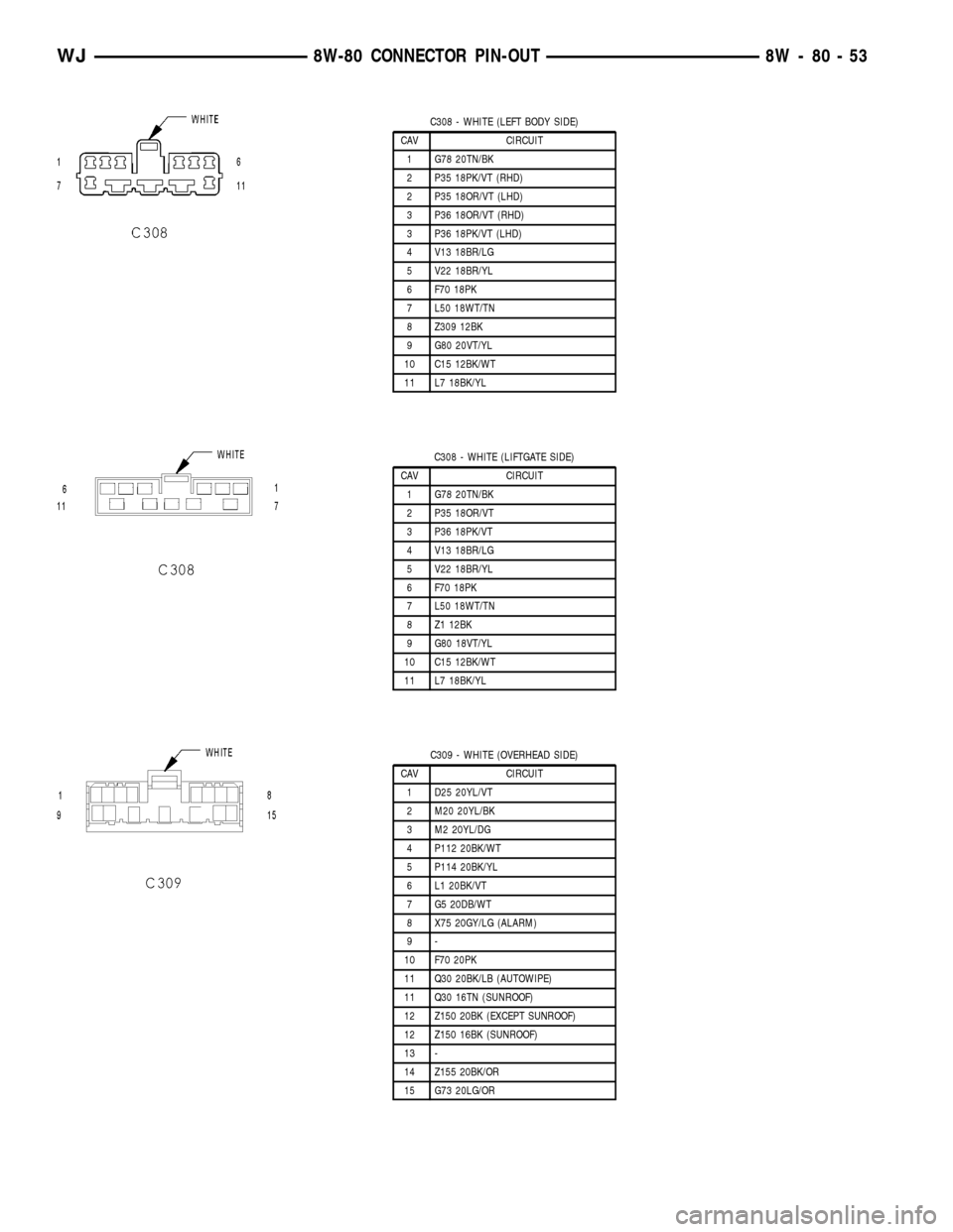
C308 - WHITE (LEFT BODY SIDE)
CAV CIRCUIT
1 G78 20TN/BK
2 P35 18PK/VT (RHD)
2 P35 18OR/VT (LHD)
3 P36 18OR/VT (RHD)
3 P36 18PK/VT (LHD)
4 V13 18BR/LG
5 V22 18BR/YL
6 F70 18PK
7 L50 18WT/TN
8 Z309 12BK
9 G80 20VT/YL
10 C15 12BK/WT
11 L7 18BK/YL
C308 - WHITE (LIFTGATE SIDE)
CAV CIRCUIT
1 G78 20TN/BK
2 P35 18OR/VT
3 P36 18PK/VT
4 V13 18BR/LG
5 V22 18BR/YL
6 F70 18PK
7 L50 18WT/TN
8 Z1 12BK
9 G80 18VT/YL
10 C15 12BK/WT
11 L7 18BK/YL
C309 - WHITE (OVERHEAD SIDE)
CAV CIRCUIT
1 D25 20YL/VT
2 M20 20YL/BK
3 M2 20YL/DG
4 P112 20BK/WT
5 P114 20BK/YL
6 L1 20BK/VT
7 G5 20DB/WT
8 X75 20GY/LG (ALARM)
9-
10 F70 20PK
11 Q30 20BK/LB (AUTOWIPE)
11 Q30 16TN (SUNROOF)
12 Z150 20BK (EXCEPT SUNROOF)
12 Z150 16BK (SUNROOF)
13 -
14 Z155 20BK/OR
15 G73 20LG/OR
WJ8W-80 CONNECTOR PIN-OUT 8W - 80 - 53
Page 1168 of 2199
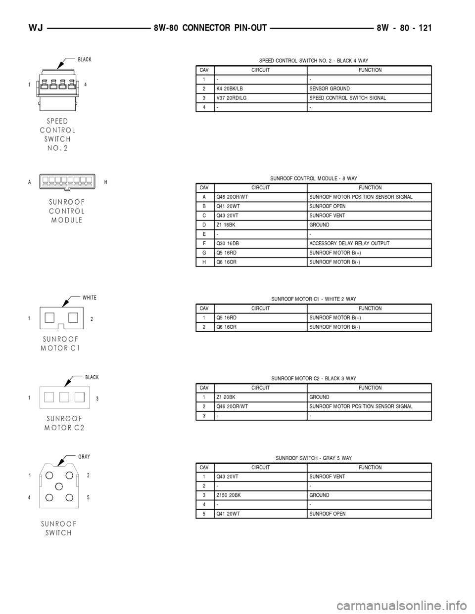
SPEED CONTROL SWITCH NO. 2 - BLACK 4 WAY
CAV CIRCUIT FUNCTION
1- -
2 K4 20BK/LB SENSOR GROUND
3 V37 20RD/LG SPEED CONTROL SWITCH SIGNAL
4- -
SUNROOF CONTROL MODULE-8WAY
CAV CIRCUIT FUNCTION
A Q46 20OR/WT SUNROOF MOTOR POSITION SENSOR SIGNAL
B Q41 20WT SUNROOF OPEN
C Q43 20VT SUNROOF VENT
D Z1 16BK GROUND
E- -
F Q30 16DB ACCESSORY DELAY RELAY OUTPUT
G Q5 16RD SUNROOF MOTOR B(+)
H Q6 16OR SUNROOF MOTOR B(-)
SUNROOF MOTOR C1 - WHITE 2 WAY
CAV CIRCUIT FUNCTION
1 Q5 16RD SUNROOF MOTOR B(+)
2 Q6 16OR SUNROOF MOTOR B(-)
SUNROOF MOTOR C2 - BLACK 3 WAY
CAV CIRCUIT FUNCTION
1 Z1 20BK GROUND
2 Q46 20OR/WT SUNROOF MOTOR POSITION SENSOR SIGNAL
3- -
SUNROOF SWITCH - GRAY 5 WAY
CAV CIRCUIT FUNCTION
1 Q43 20VT SUNROOF VENT
2- -
3 Z150 20BK GROUND
4- -
5 Q41 20WT SUNROOF OPEN
WJ8W-80 CONNECTOR PIN-OUT 8W - 80 - 121
Page 1185 of 2199
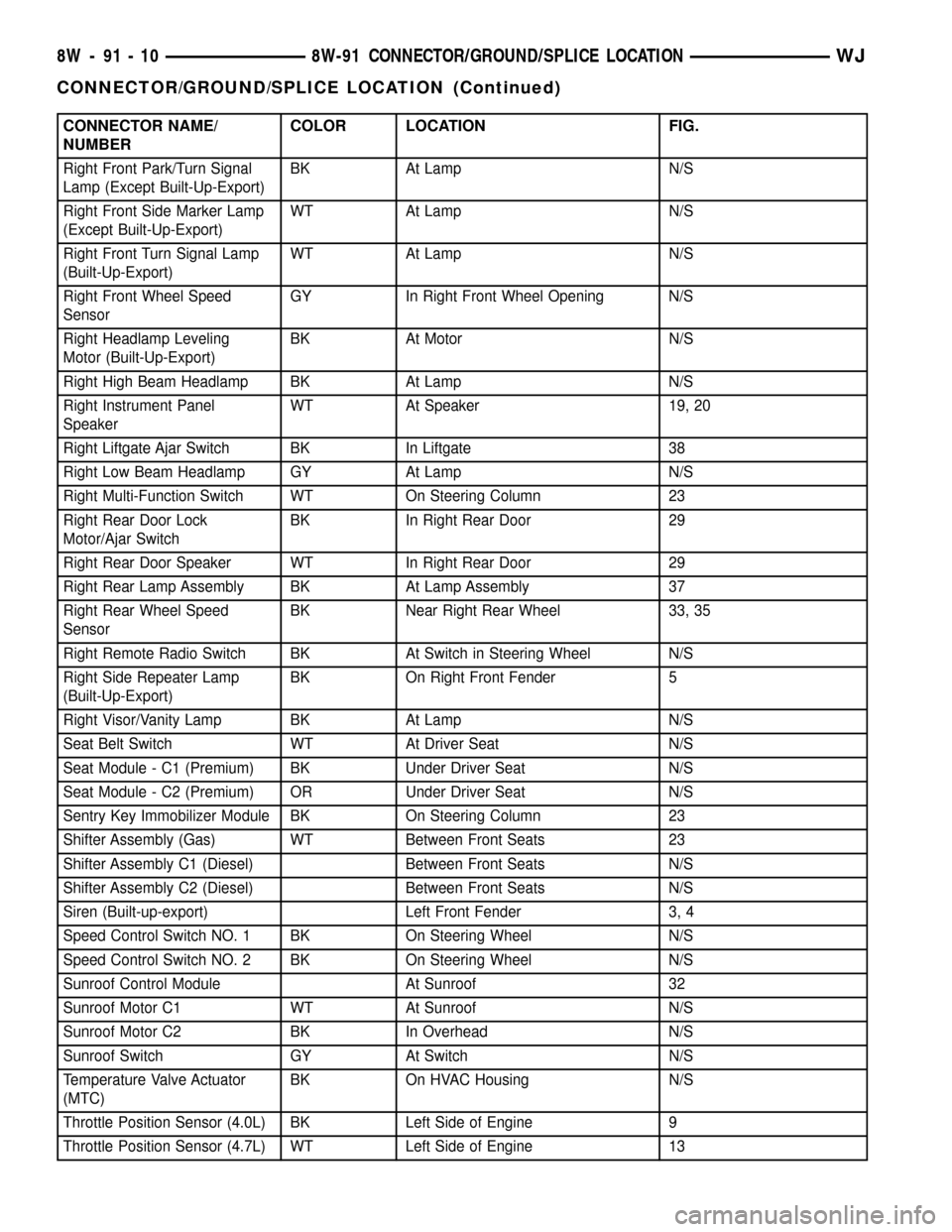
CONNECTOR NAME/
NUMBERCOLOR LOCATION FIG.
Right Front Park/Turn Signal
Lamp (Except Built-Up-Export)BK At Lamp N/S
Right Front Side Marker Lamp
(Except Built-Up-Export)WT At Lamp N/S
Right Front Turn Signal Lamp
(Built-Up-Export)WT At Lamp N/S
Right Front Wheel Speed
SensorGY In Right Front Wheel Opening N/S
Right Headlamp Leveling
Motor (Built-Up-Export)BK At Motor N/S
Right High Beam Headlamp BK At Lamp N/S
Right Instrument Panel
SpeakerWT At Speaker 19, 20
Right Liftgate Ajar Switch BK In Liftgate 38
Right Low Beam Headlamp GY At Lamp N/S
Right Multi-Function Switch WT On Steering Column 23
Right Rear Door Lock
Motor/Ajar SwitchBK In Right Rear Door 29
Right Rear Door Speaker WT In Right Rear Door 29
Right Rear Lamp Assembly BK At Lamp Assembly 37
Right Rear Wheel Speed
SensorBK Near Right Rear Wheel 33, 35
Right Remote Radio Switch BK At Switch in Steering Wheel N/S
Right Side Repeater Lamp
(Built-Up-Export)BK On Right Front Fender 5
Right Visor/Vanity Lamp BK At Lamp N/S
Seat Belt Switch WT At Driver Seat N/S
Seat Module - C1 (Premium) BK Under Driver Seat N/S
Seat Module - C2 (Premium) OR Under Driver Seat N/S
Sentry Key Immobilizer Module BK On Steering Column 23
Shifter Assembly (Gas) WT Between Front Seats 23
Shifter Assembly C1 (Diesel) Between Front Seats N/S
Shifter Assembly C2 (Diesel) Between Front Seats N/S
Siren (Built-up-export) Left Front Fender 3, 4
Speed Control Switch NO. 1 BK On Steering Wheel N/S
Speed Control Switch NO. 2 BK On Steering Wheel N/S
Sunroof Control Module At Sunroof 32
Sunroof Motor C1 WT At Sunroof N/S
Sunroof Motor C2 BK In Overhead N/S
Sunroof Switch GY At Switch N/S
Temperature Valve Actuator
(MTC)BK On HVAC Housing N/S
Throttle Position Sensor (4.0L) BK Left Side of Engine 9
Throttle Position Sensor (4.7L) WT Left Side of Engine 13
8W - 91 - 10 8W-91 CONNECTOR/GROUND/SPLICE LOCATIONWJ
CONNECTOR/GROUND/SPLICE LOCATION (Continued)
Page 1191 of 2199
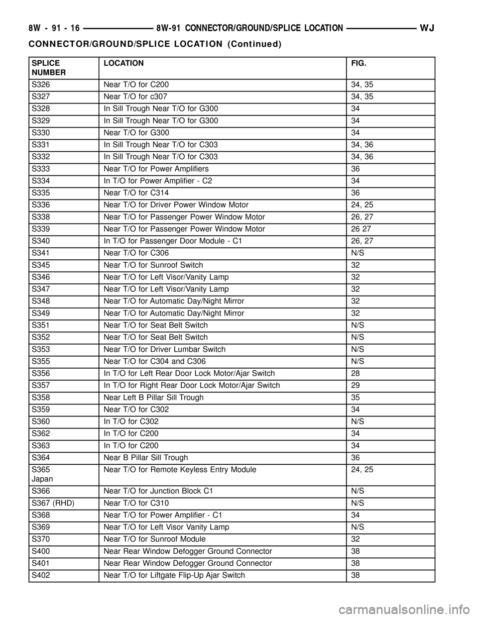
SPLICE
NUMBERLOCATION FIG.
S326 Near T/O for C200 34, 35
S327 Near T/O for c307 34, 35
S328 In Sill Trough Near T/O for G300 34
S329 In Sill Trough Near T/O for G300 34
S330 Near T/O for G300 34
S331 In Sill Trough Near T/O for C303 34, 36
S332 In Sill Trough Near T/O for C303 34, 36
S333 Near T/O for Power Amplifiers 36
S334 In T/O for Power Amplifier - C2 34
S335 Near T/O for C314 36
S336 Near T/O for Driver Power Window Motor 24, 25
S338 Near T/O for Passenger Power Window Motor 26, 27
S339 Near T/O for Passenger Power Window Motor 26 27
S340 In T/O for Passenger Door Module - C1 26, 27
S341 Near T/O for C306 N/S
S345 Near T/O for Sunroof Switch 32
S346 Near T/O for Left Visor/Vanity Lamp 32
S347 Near T/O for Left Visor/Vanity Lamp 32
S348 Near T/O for Automatic Day/Night Mirror 32
S349 Near T/O for Automatic Day/Night Mirror 32
S351 Near T/O for Seat Belt Switch N/S
S352 Near T/O for Seat Belt Switch N/S
S353 Near T/O for Driver Lumbar Switch N/S
S355 Near T/O for C304 and C306 N/S
S356 In T/O for Left Rear Door Lock Motor/Ajar Switch 28
S357 In T/O for Right Rear Door Lock Motor/Ajar Switch 29
S358 Near Left B Pillar Sill Trough 35
S359 Near T/O for C302 34
S360 In T/O for C302 N/S
S362 In T/O for C200 34
S363 In T/O for C200 34
S364 Near B Pillar Sill Trough 36
S365
JapanNear T/O for Remote Keyless Entry Module 24, 25
S366 Near T/O for Junction Block C1 N/S
S367 (RHD) Near T/O for C310 N/S
S368 Near T/O for Power Amplifier - C1 34
S369 Near T/O for Left Visor Vanity Lamp N/S
S370 Near T/O for Sunroof Module 32
S400 Near Rear Window Defogger Ground Connector 38
S401 Near Rear Window Defogger Ground Connector 38
S402 Near T/O for Liftgate Flip-Up Ajar Switch 38
8W - 91 - 16 8W-91 CONNECTOR/GROUND/SPLICE LOCATIONWJ
CONNECTOR/GROUND/SPLICE LOCATION (Continued)
Page 1874 of 2199
BODY
TABLE OF CONTENTS
page page
BODY
DIAGNOSIS AND TESTING
WATER LEAKS........................1
WIND NOISE..........................2
STANDARD PROCEDURE
STANDARD PROCEDURE - BODY
LUBRICATION.........................2
STANDARD PROCEDURE - DRILLING AND
WELDING............................3
SPECIFICATIONS
BODY LUBRICANTS....................3
SPECIFICATIONS - TORQUE.............4
SPECIAL TOOLS
BODY...............................4DECKLID/HATCH/LIFTGATE/TAILGATE........5
DOOR - FRONT.........................11
DOORS - REAR.........................19
EXTERIOR.............................25
HOOD.................................33
INSTRUMENT PANEL SYSTEM.............36
INTERIOR..............................69
PAINT.................................81
SEATS................................83
STATIONARY GLASS.....................93
SUNROOF.............................96
WEATHERSTRIP/SEALS..................105
BODY STRUCTURE.....................112
BODY
DIAGNOSIS AND TESTING
WATER LEAKS
Water leaks can be caused by poor sealing,
improper body component alignment, body seam
porosity, missing plugs, or blocked drain holes. Cen-
trifugal and gravitational force can cause water to
drip from a location away from the actual leak point,
making leak detection difficult. All body sealing
points should be water tight in normal wet-driving
conditions. Water flowing downward from the front of
the vehicle should not enter the passenger or luggage
compartment. Moving sealing surfaces will not
always seal water tight under all conditions. At
times, side glass or door seals will allow water to
enter the passenger compartment during high pres-
sure washing or hard driving rain (severe) condi-
tions. Overcompensating on door or glass
adjustments to stop a water leak that occurs under
severe conditions can cause premature seal wear and
excessive closing or latching effort. After completing
a repair, water test vehicle to verify leak has stopped
before returning vehicle to use.
VISUAL INSPECTION BEFORE WATER LEAK TESTS
Verify that floor and body plugs are in place, body
drains are clear, and body components are properly
aligned and sealed. If component alignment or seal-
ing is necessary, refer to the appropriate section of
this group for proper procedures.
WATER LEAK TESTS
WARNING: DO NOT USE ELECTRIC SHOP LIGHTS
OR TOOLS IN WATER TEST AREA. PERSONAL
INJURY CAN RESULT.
When the conditions causing a water leak have
been determined, simulate the conditions as closely
as possible.
²If a leak occurs with the vehicle parked in a
steady light rain, flood the leak area with an open-
ended garden hose.
²If a leak occurs while driving at highway speeds
in a steady rain, test the leak area with a reasonable
velocity stream or fan spray of water. Direct the
spray in a direction comparable to actual conditions.
²If a leak occurs when the vehicle is parked on an
incline, hoist the end or side of the vehicle to simu-
late this condition. This method can be used when
the leak occurs when the vehicle accelerates, stops or
turns. If the leak occurs on acceleration, hoist the
front of the vehicle. If the leak occurs when braking,
hoist the back of the vehicle. If the leak occurs on left
turns, hoist the left side of the vehicle. If the leak
occurs on right turns, hoist the right side of the vehi-
cle. For hoisting recommendations refer to Group 0,
Lubrication and Maintenance, General Information
section.
WATER LEAK DETECTION
To detect a water leak point-of-entry, do a water
test and watch for water tracks or droplets forming
on the inside of the vehicle. If necessary, remove inte-
rior trim covers or panels to gain visual access to the
WJBODY 23 - 1
Page 1877 of 2199
SPECIFICATIONS - TORQUE
TORQUE SPECIFICATIONS
DESCRIPTION N´m Ft. Lbs. In. Lbs.
BUCKET SEAT BACK FRAME RECLINER BOLTS TO SEAT CUSHION
FRAME28 20 Ð
BUCKET SEAT RECLINER TO SEAT BACK FRAME BOLTS 28 20 Ð
BUCKET SEAT TRACK ADJUSTER NUTS TO SEAT CUSHION FRAME 28 20 Ð
FRONT BUCKET SEAT TO FLOOR PAN BOLTS 40 30 Ð
FRONT BUCKET SEAT TO FLOOR PAN FRONT BOLTS 40 30 Ð
FRONT DOOR HINGE BOLTS 35 26 Ð
FRONT DOOR LATCH TO DOOR SCREWS 10 Ð 89
FRONT DOOR STRIKER TO B-PILLAR 28 20 Ð
HOOD LATCH TO RADIATOR CROSSMEMBER 11 8 Ð
LIFT GATE LATCH STRIKER TO D-PILLAR NUTS 10 Ð 89
REAR DOOR LATCH TO DOOR SCREWS 10 Ð 89
REAR DOOR STRIKER TO C-PILLAR SCREWS 28 20 Ð
REAR SEAT BACK LATCH/HINGE TO SEAT BACK FRAME 28 20 Ð
REAR SEAT BACK LEFT SIDE SUPPORT BRACKET TO CENTER PIVOT
BRACKET28 20 Ð
REAR SEAT BACK RIGHT SIDE SUPPORT BRACKET 28 20 Ð
REAR SEAT CUSHION LATCH BASE PANEL SCREWS 8 Ð 75
REAR SEAT CUSHION TO FLOOR PAN BOLTS 11 8 Ð
SUNROOF MODULE TO ROOF PANEL NUTS 11 8 Ð
SPECIAL TOOLS
BODY
Remover, Moldings C-4829
23 - 4 BODYWJ
BODY (Continued)
Page 1950 of 2199

HEADLINER
REMOVAL
CAUTION: The headliner is a one-piece, molded
component. It has limited flexibility and must not be
bent. Damage may possibly result.
(1) Record radio presets and disconnect negative
battery cable.
(2) Remove A pillar trim moldings (Refer to 23 -
BODY/INTERIOR/A-PILLAR TRIM - REMOVAL).
(3) Remove B pillar upper trim moldings (Refer to
23 - BODY/INTERIOR/B-PILLAR UPPER TRIM -
REMOVAL).
(4) Remove C pillar trim moldings (Refer to 23 -
BODY/INTERIOR/C-PILLAR TRIM - REMOVAL).
(5) Remove D pillar trim molding (Refer to 23 -
BODY/INTERIOR/D-PILLAR TRIM - REMOVAL).
(6) Remove the sun visors (Refer to 23 - BODY/IN-
TERIOR/SUN VISOR - REMOVAL).
(7) Disconnect the vanity lamp electrical connector.
(8) Remove assist handles from roof rails (Refer to
23 - BODY/INTERIOR/ASSIST HANDLE - REMOV-
AL).
(9) Remove dome lamp and overhead console, if
equipped.
(10) Remove rear cargo/dome lamp.
(11) Remove sun roof pinch welt, if equipped.
(12) Disengage rear washer hose from liftgate (Fig.
9).
(13) Disengage the wire harness connectors at rear
of headliner.
(14) Disconnect the rear washer hose at the left
ªAº pillar (Fig. 10).
(15) Disengage the wire harness for the sunroof, if
equipped.
(16) Fold down the rear seats, move the front seats
full forward, and lower the front seat backs.
(17) Partially lower the headliner and disengage
the sunroof drain hoses, if equipped (Fig. 11).
(18) With the aid of an assistant, remove the head-
liner through the liftgate opening.
INSTALLATION
(1) With the aid of an assistant, position the head-
liner in the vehicle.
(2) Connect the sunroof drain hoses, if equipped.
(3) Connect the sunroof harness, the rear wire har-
nesses, and the washer hose at the ªAº pillar and at
the liftgate.
(4) Install the sunroof pinch welt, if equipped.
(5) Install the roof rail assist handles (Refer to 23 -
BODY/INTERIOR/ASSIST HANDLE - INSTALLA-
TION).
Fig. 9 Liftgate Washer Hose Routing at Rear of
Headliner
1 - ROOF
2 - REAR WASHER HOSE ROUTING
3 - REAR WASHER HOSE
4 - HEADLINER
Fig. 10 Rear Liftgate Washer Hose Routing at A
Pillar
1 - OVERHEAD CONSOLE WIRE HARNESS
2 - ROOF
3 - REAR WASHER HOSE
4 - REAR WASHER HOSE ROUTING
5 - HEADLINER
WJINTERIOR 23 - 77
Page 1951 of 2199

(6) Install the sun visors (Refer to 23 - BODY/IN-
TERIOR/SUN VISOR - INSTALLATION).
(7) Install the overhead console, if equipped.
(8) Install the rear cargo/dome lamp.
(9) Install the D pillar trim (Refer to 23 - BODY/
INTERIOR/D-PILLAR TRIM - INSTALLATION).(10) Install the C pillar trim (Refer to 23 - BODY/
INTERIOR/C-PILLAR TRIM - INSTALLATION).
(11) Install the upper B pillar trim (Refer to 23 -
BODY/INTERIOR/B-PILLAR UPPER TRIM -
INSTALLATION).
(12) Install the A pillar trim (Refer to 23 - BODY/
INTERIOR/A-PILLAR TRIM - INSTALLATION).
(13) Connect the negative battery cable.
Fig. 11 Headliner
1 - SUNROOF PINCH WELT
2 - ROOF
3 - REAR WASHER HOSE4 - HEADLINER
5 - SUNROOF
23 - 78 INTERIORWJ
HEADLINER (Continued)
Page 1969 of 2199

SUNROOF
TABLE OF CONTENTS
page page
SUNROOF
DESCRIPTION.........................96
DIAGNOSIS AND TESTING - SUNROOF......96
DRAIN TUBE
REMOVAL............................100
INSTALLATION........................100
CONTROL MODULE
REMOVAL............................101
INSTALLATION........................101
DRIVE MOTOR
REMOVAL............................101
INSTALLATION........................101
WIND DEFLECTOR
REMOVAL............................102INSTALLATION........................102
GLASS PANEL
REMOVAL............................102
INSTALLATION........................103
ADJUSTMENTS
ADJUSTMENTS - FIT.................103
ADJUSTMENT - TIMING...............103
SUNSHADE
REMOVAL............................103
INSTALLATION........................103
HOUSING ASSEMBLY
REMOVAL............................104
INSTALLATION........................104
SUNROOF
DESCRIPTION
WARNING: Keep fingers and other body parts out
of sunroof opening at all times.
The sunroof features a power sliding glass panel
and a sunshade which can be manually positioned
anywhere along its travel, rearward of glass panel
front edge.
The sunroof is electrically operated from a switch
located on the mini overhead console. To operate the
sunroof the ignition switch must be in the On/Run
position. The sunroof has both manual and Express
Open modes of operation when opening. To open the
sunroof in the Express Open mode, the switch is
pressed rearward for less than1 second.This causes
the sunroof glass to automatically retract and stop at
a position slightly forward of full open that reduces
low speed wind buffeting. The sunroof can also be
opened manually by pressing and holding the switch
rearward. Once the switch is held reward for more
than1 second,the glass will retract in the manual
mode. Releasing the switch at any time during travel
will cause the sunroof to stop at the current position.
To close the sunroof from an open position, the
switch must be pushed forward and held until the
sunroof glass comes to a complete stop. Releasing the
switch at any time in this mode will cause the sun-
roof to stop at the current position.
To vent the sunroof from the closed position, the
switch is pushed forward and held. Releasing theswitch at any time during travel will cause the sun-
roof to stop at the current vent position. To reach the
fully vented position, continue to hold the switch for-
ward until vent motion stops. To close the sunroof
from the vent position, push and hold the switch
rearward until the glass comes to a complete stop.
DIAGNOSIS AND TESTING - SUNROOF
CAUTION: The sunroof motor is only to be powered
through the vehicle battery and vehicle wire har-
ness. Applying power to the sunroof motor leads
will cause failure of the sunroof control unit.
Before beginning sunroof diagnostics verify that all
other power accessories are in proper operating con-
dition. Refer to Sunroof Diagnostic Chart for possible
causes. If not, a common electrical problem may
exist. Refer to Group 8W, Wiring Diagrams, of this
publication for circuit, splice and component descrip-
tions. Check the condition of the circuit protection
(20 amp high current fuse (battery feed) located in
the Power Distribution Center (PDC). Check the
cover of the PDC for location of the fuse. Check for
correct operation of the sunroof delay relay. Inspect
all wiring connector pins for proper engagement and
continuity. Check for battery voltage at battery and
ignition pins of the power sunroof express module
wiring connector. Refer to Group 8W, Wiring Dia-
grams, for circuit information. The controller will not
operate at less than 10 volts. Check the ground at
the sunroof express module.
Before beginning diagnosis for wind noise or water
leaks, verify that the problem was not caused by
23 - 96 SUNROOFWJ