Vin JEEP GRAND CHEROKEE 2002 WJ / 2.G Workshop Manual
[x] Cancel search | Manufacturer: JEEP, Model Year: 2002, Model line: GRAND CHEROKEE, Model: JEEP GRAND CHEROKEE 2002 WJ / 2.GPages: 2199, PDF Size: 76.01 MB
Page 1903 of 2199

(3) Install fascia, refer to (Refer to 13 - FRAMES
& BUMPERS/BUMPERS/FRONT FASCIA - INSTAL-
LATION).
HEADLAMP MOUNTING
MODULE
REMOVAL
CAUTION: Take special care when handling the
HMM not to damage the upper mounting tabs. Step
#3 must be performed prior to removing HMM from
the vehicle to prevent damage to HMM.
(1) Remove fascia, refer to (Refer to 13 - FRAMES
& BUMPERS/BUMPERS/FRONT FASCIA - REMOV-
AL).
(2) Remove inner fender liner.
(3) Reach into the wheelhouse opening and disen-
gage the retainer attaching the HMM to each side of
the body.
(4) Remove bolts attaching headlamp mounting
module to body (Fig. 10).
(5) Disconnect headlamp wire harness connectors.
(6) Separate headlamp mounting module from
vehicle.
INSTALLATION
(1) Position headlamp mounting module at vehicle.
(2) Connect headlamp wire harness connectors.
(3) Engage the retainer attaching the HMM to
each side of the body.
(4) Install bolts attaching headlamp mounting
module to body (Fig. 10).
(5) Install inner fender liner.
(6) Install front fascia, refer to (Refer to 13 -
FRAMES & BUMPERS/BUMPERS/FRONT FASCIA
- INSTALLATION).
LUGGAGE RACK
REMOVAL
NOTE: The skid strips are attached to the roof
panel with adhesive.
(1) Using a trim stick, or other suitable device, pry
support cover off.
(2) If necessary, slide the crossbars to expose the
screws attaching the slide rails to the supports.
(3) Remove the screws retaining the slide rails to
the supports.
Fig. 10 Headlamp Mounting Module
1 - CONNECTOR
2 - CONNECTOR3 - MOUNTING BRACKET
4 - HEADLAMP MODULE
23 - 30 EXTERIORWJ
GRILLE (Continued)
Page 1920 of 2199

REMOVAL
WARNING: ON VEHICLES EQUIPPED WITH AIR-
BAGS, DISABLE THE AIRBAG SYSTEM BEFORE
ATTEMPTING ANY STEERING WHEEL, STEERING
COLUMN, OR INSTRUMENT PANEL COMPONENT
DIAGNOSIS OR SERVICE. DISCONNECT AND ISO-
LATE THE BATTERY NEGATIVE (GROUND) CABLE,
THEN WAIT TWO MINUTES FOR THE AIRBAG SYS-
TEM CAPACITOR TO DISCHARGE BEFORE PER-
FORMING FURTHER DIAGNOSIS OR SERVICE. THIS
IS THE ONLY SURE WAY TO DISABLE THE AIRBAG
SYSTEM. FAILURE TO TAKE THE PROPER PRE-
CAUTIONS COULD RESULT IN ACCIDENTAL AIR-
BAG DEPLOYMENT AND POSSIBLE PERSONAL
INJURY.
(1) Disconnect and isolate the battery negative
cable.
(2) Roll the glove box down from the instrument
panel. (Refer to 23 - BODY/INSTRUMENT PANEL/
GLOVE BOX - STANDARD PROCEDURE - GLOVE
BOX ROLL DOWN).
NOTE: Be certain to use care not to damage or
remove the glove box hinge bumpers on the lower
instrument panel glove box opening reinforcement
when removing the glove box from the instrument
panel.
(3) Firmly grip both ends of the glove box door,
then twist and pull the door as necessary to disen-
gage the inboard hinge hook from the inboard hinge
pin on the instrument panel and reorient the hook to
the underside of the hinge pin (Fig. 18).(4) Raise the glove box door until it is perpendicu-
lar to the instrument panel.
(5) Twist the door slightly in the counterclockwise
direction and use a jiggling action to disengage the
remaining two hinge hooks from their respective
hinge pins on the instrument panel.
(6) Remove the glove box from the instrument
panel.
INSTALLATION
WARNING: ON VEHICLES EQUIPPED WITH AIR-
BAGS, DISABLE THE AIRBAG SYSTEM BEFORE
ATTEMPTING ANY STEERING WHEEL, STEERING
COLUMN, OR INSTRUMENT PANEL COMPONENT
DIAGNOSIS OR SERVICE. DISCONNECT AND ISO-
LATE THE BATTERY NEGATIVE (GROUND) CABLE,
THEN WAIT TWO MINUTES FOR THE AIRBAG SYS-
TEM CAPACITOR TO DISCHARGE BEFORE PER-
FORMING FURTHER DIAGNOSIS OR SERVICE. THIS
IS THE ONLY SURE WAY TO DISABLE THE AIRBAG
SYSTEM. FAILURE TO TAKE THE PROPER PRE-
CAUTIONS COULD RESULT IN ACCIDENTAL AIR-
BAG DEPLOYMENT AND POSSIBLE PERSONAL
INJURY.
NOTE: Be certain to use care not to damage or
remove the glove box hinge bumpers on the lower
instrument panel glove box opening reinforcement
when installing the glove box onto the instrument
panel.
(1) Position the glove box to the instrument panel
with the outboard hinge hook oriented over the out-
board hinge pin and the center hinge hook oriented
under the center hinge pin (Fig. 18).
(2) Raise the glove box door until it is perpendicu-
lar to the instrument panel.
(3) Firmly grip both ends of the glove box door and
twist the door slightly in the clockwise direction to
engage the inboard glove box hinge hook over the
inboard hinge pin on the instrument panel.
(4) Roll the glove box back up into the instrument
panel. (Refer to 23 - BODY/INSTRUMENT PANEL/
GLOVE BOX - STANDARD PROCEDURE - GLOVE
BOX ROLL DOWN).
(5) Reconnect the battery negative cable.
Fig. 18 Glove Box Remove/Install
1 - GLOVE BOX HINGE HOOKS AND HINGE PINS (3)
WJINSTRUMENT PANEL SYSTEM 23 - 47
GLOVE BOX (Continued)
Page 1966 of 2199

STATIONARY GLASS
TABLE OF CONTENTS
page page
DOOR GLASS
REMOVAL.............................93
INSTALLATION.........................93
QUARTER WINDOW
REMOVAL.............................93INSTALLATION.........................93
WINDSHIELD
REMOVAL.............................94
INSTALLATION.........................95
DOOR GLASS
REMOVAL
(1) Remove door trim panel.
(2) Remove waterdam.
(3) Remove inner belt weatherstrip.
(4) Remove bolt attaching bottom of rear glass run
channel to door.
(5) Pull run channel downward and separate from
door.
(6) Remove screws attaching stationary door glass
frame to door (Fig. 1) and (Fig. 2).
(7) Separate stationary door glass from door.
INSTALLATION
(1) Position stationary door glass in door.
(2) Install screws attaching stationary door glass
frame to door.
(3) Install glass run channel.
(4) Install inner belt weatherstrip.
(5) Install waterdam.
(6) Install door trim panel.
QUARTER WINDOW
REMOVAL
(1) Cut urethane bonding from around quarter
window glass using a suitable sharp cold knife. A
pneumatic cutting device can be used if available.
(2) Separate glass from vehicle.
INSTALLATION
CAUTION: Open a window before installing glass.
This will avoid pressurizing the passenger compart-
ment. If a door or liftgate is slammed before ure-
thane is cured, water leaks can result.
The window opening fence should be cleaned of old
urethane bonding material.
(1) Clean inside of glass with Mopar Glass Cleaner
and lint-free cloth.
(2) Apply PVC (vinyl) primer 25 mm (1 in.) wide
around edge of glass. Wipe with clean/dry lint-free
cloth.
Fig. 1 Stationary Door Glass
1 - DOOR
2 - STATIONARY DOOR GLASS
Fig. 2 Stationary Door Glass
1 - STATIONARY DOOR GLASS
2 - DOOR
WJSTATIONARY GLASS 23 - 93
Page 1967 of 2199

(3) Apply fence primer around edge of fence. Allow
at least eighteen minutes drying time.
(4) Apply a 10 mm (0.4 in.) bead of urethane
around window vinyl border location.
(5)
Position glass into window opening and lock clips
into place (Fig. 3).
WINDSHIELD
REMOVAL
(1) Remove inside rear view mirror.
(2) Remove cowl cover.
(3) Remove screws attaching windshield side mold-
ing to A-pillar (Fig. 4).
(4) Remove upper windshield molding.
(5) Cut urethane bonding from around windshield
using a suitable sharp cold knife. A pneumatic cut-
ting device can be used if available (Fig. 5).
(6) Separate windshield from vehicle.
Fig. 3 Quarter Window Glass
1 - CLIP
2 - ROOF PANEL
3 - QUARTER WINDOW GLASS
Fig. 4 Windshield
1 - SIDE MOLDING
2 - SUPPORT SPACER
3 - UPPER MOLDING
4 - SIDE MOLDING
5 - ROOF PANEL
6 - SUPPORT SPACER7 - BLOCKER
8 - STUD
9 - SUPPORT SPACER
10 - WINDSHIELD
11 - ALIGNMENT SPACER
23 - 94 STATIONARY GLASSWJ
QUARTER WINDOW (Continued)
Page 1974 of 2199

CONTROL MODULE
REMOVAL
(1) Move the glass panel to the fully closed posi-
tion.
(2) Remove the A-pillar trim. (Refer to 23 - BODY/
INTERIOR/A-PILLAR TRIM - REMOVAL)
(3) Remove the sun visors. (Refer to 23 - BODY/
INTERIOR/SUN VISOR - REMOVAL)
(4) Remove the overhead console. (Refer to 8 -
ELECTRICAL/OVERHEAD CONSOLE - REMOVAL)
(5) Lower headliner as necessary to gain access to
the sunroof express module.
(6) Disconnect the express module wire harness
connectors.
(7) Remove express module screw.
(8) Remove express module from the keyway by
sliding module towards the center of the vehicle.
INSTALLATION
(1) Insert sunroof express module in the keyway
located in the sunroof module and slide the module
outward to lock it into position.
(2) Install the sunroof express module screw.
(3) Connect the wire connectors to the sunroof
express module.
(4) Install the headliner into position.
(5) Install the overhead console. (Refer to 8 -
ELECTRICAL/OVERHEAD CONSOLE - INSTALLA-
TION)
(6) Install the sun visors. (Refer to 23 - BODY/IN-
TERIOR/SUN VISOR - INSTALLATION)
(7) Install the A-pillar trim. (Refer to 23 - BODY/
INTERIOR/A-PILLAR TRIM - INSTALLATION)
(8) Test sunroof operation, adjust if necessary.
(Refer to 23 - BODY/SUNROOF/GLASS PANEL -
ADJUSTMENTS)
DRIVE MOTOR
REMOVAL
CAUTION: The sunroof system is timed from the
factory so that the motor shuts off automatically
when the sunroof window reaches a certain posi-
tion. Extreme care must be taken when removing
the motor, timing may be thrown off causing possi-
ble damage to the sunroof system. Anytime the
motor is removed from the sunroof assembly the
sunroof glass panel must be in the FULLY CLOSED
POSITION or the unit will be out of timing. The drive
motor cannot be reset to the park position after
being removed.CAUTION: The sunroof motor should only be pow-
ered through the vehicle battery and sunroof wire
harness. Applying power to the sunroof motor leads
will cause failure of the control module.
(1) Move glass panel to the fully closed position.
(2) Remove the A-pillar trim. (Refer to 23 - BODY/
INTERIOR/A-PILLAR TRIM - REMOVAL)
(3) Remove the B-pillar upper trim. (Refer to 23 -
BODY/INTERIOR/B-PILLAR UPPER TRIM -
REMOVAL)
(4) Remove the C-pillar trim. (Refer to 23 - BODY/
INTERIOR/C-PILLAR TRIM - REMOVAL)
(5) Remove the D-pillar trim. (Refer to 23 - BODY/
INTERIOR/D-PILLAR TRIM - REMOVAL)
(6) Remove the sunvisors. (Refer to 23 - BODY/IN-
TERIOR/SUN VISOR - REMOVAL)
(7) Remove the overhead console. (Refer to 8 -
ELECTRICAL/OVERHEAD CONSOLE - REMOVAL)
(8) Disconnect the control switch wire connector.
(9) Remove headliner as necessary to gain access
to sunroof drive motor. Refer to Headliner Removal
and Installation for proper procedures.
(10) Disconnect the drive motor wire harness con-
nectors (Fig. 3).
(11) Remove drive motor fasteners and remove
motor from the sunroof housing.
INSTALLATION
(1) Ensure that the window is in the fully closed
position before mounting the motor. If motor fails
with the window in the open position the sunroof
glass panel timing will have to be timed. The new
motor comes in the fully closed position and with a
gage for setting cable timing. (Refer to 23 - BODY/
SUNROOF/GLASS PANEL - ADJUSTMENTS - TIM-
ING)
(2) Place drive motor into position on the sunroof
housing and install fasteners.
Fig. 3 Sunroof Drive Motor and Express Module
1 - EXPRESS MODULE
2 - SCREW
WJSUNROOF 23 - 101
Page 1976 of 2199

INSTALLATION
NOTE: Sunroof glass must be set in place and
attached as close as possible to flush with the roof
surface. For wind noise reasons, care must be
taken to ensure that the glass is not remounted
either a) Overflush to the roof surface at the front
edge of the glass, or b) Underflush to the roof sur-
face at the rear edge of the glass.
(1) Position glass panel in to opening.
(2) Start the four attaching screws.
(3) Tighten screws.
(4) Verify sunroof operation and alignment. Check
fit and adjust as necessary. (Refer to 23 - BODY/
SUNROOF/GLASS PANEL - ADJUSTMENTS - FIT)
ADJUSTMENTS
ADJUSTMENTS - FIT
(1) Move the sunshade rearward to the open posi-
tion.
(2) Move the sunroof glass panel to the fully closed
position.
(3) Loosen the forward screws on each side enough
to make the front adjustment.
(4) Adjust the front of the sunroof glass panel 1
mm (1/32 inch) below the top surface of the roof
panel.
(5) Tighten the front two screws.
(6) Loosen the rear screws on each side enough to
make the rear adjustment.
(7) Adjust the rear of the sunroof glass panel 1
mm (1/32 inch) above the top surface of the roof
panel.
(8) Tighten the rear two screws.
(9) Check for proper fit. If not OK, repeat glass
panel adjustment.
ADJUSTMENT - TIMING
NOTE: A gage comes with the new motor.
(1) If the glass panel was not in the fully closed
position, when the motor was removed, the sunroof
glass panel needs to be timed, before the new motor
is installed.
(2) Remove sunroof glass panel.
(3) Set gage into the track near the rear of the
opening between the driver slide and the bracket
(Fig. 6).
(4) Move the driver slide forward or aft to get
proper setting.
(5) Repeat the operation on the other side.
(6) Install drive motor.
SUNSHADE
REMOVAL
(1) Open sunroof approximately 50% of the way.
(2) Push sunshade down until tabs clear glass.
(3) Move sunshade forward of glass panel.
(4) Compress the spring loaded plungers holding
the guide blocks in the track.
(5) Slide the sunshade forward while lifting the
front through the opening until the rear guide blocks
are accessible.
CAUTION: Use care not to crease the sunshade
when removing or installing.
(6) Disengage rear guide blocks from track.
INSTALLATION
(1) Install the sunshade from outside of the vehicle
with the sunroof fully open.
(2) Put rear guide blocks into sunshade guide
track.
(3) Push sunshade back and down through the
sunroof opening.
(4) Using a flat blade tool, put front guide blocks
into the sunshade track. By pushing the block
towards the center of the vehicle.
(5) Move the glass panel to approximately halfway
to the fully closed position.
Fig. 6 Sunroof Drive Cable Timing
1 - MOVE DRIVER SLIDE FORWARD/AFT
2 - GAGE
WJSUNROOF 23 - 103
GLASS PANEL (Continued)
Page 2096 of 2199

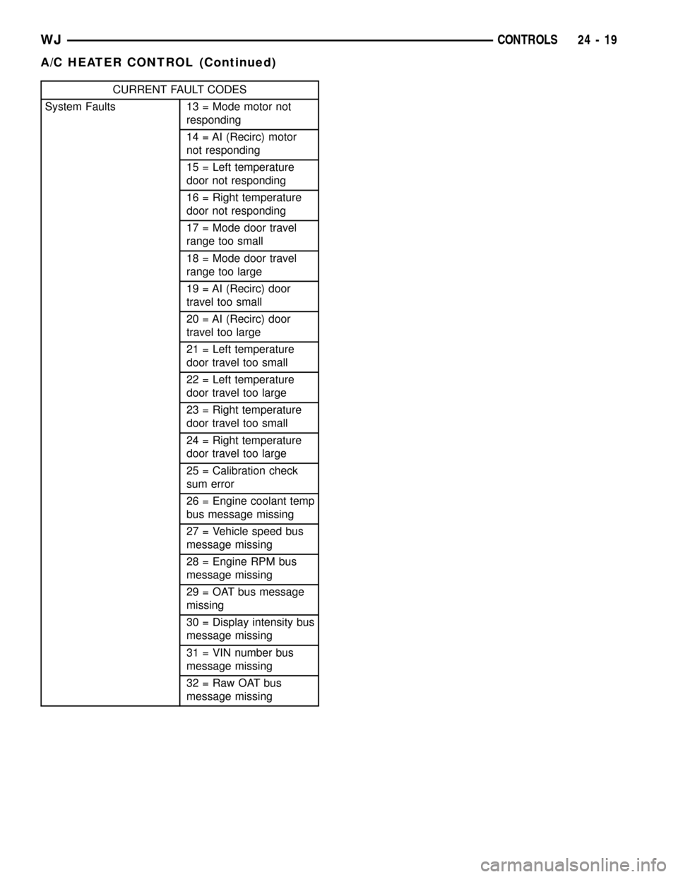
CURRENT FAULT CODES
System Faults 13 = Mode motor not
responding
14 = AI (Recirc) motor
not responding
15 = Left temperature
door not responding
16 = Right temperature
door not responding
17 = Mode door travel
range too small
18 = Mode door travel
range too large
19 = AI (Recirc) door
travel too small
20 = AI (Recirc) door
travel too large
21 = Left temperature
door travel too small
22 = Left temperature
door travel too large
23 = Right temperature
door travel too small
24 = Right temperature
door travel too large
25 = Calibration check
sum error
26 = Engine coolant temp
bus message missing
27 = Vehicle speed bus
message missing
28 = Engine RPM bus
message missing
29 = OAT bus message
missing
30 = Display intensity bus
message missing
31 = VIN number bus
message missing
32 = Raw OAT bus
message missing
WJCONTROLS 24 - 19
A/C HEATER CONTROL (Continued)
Page 2097 of 2199

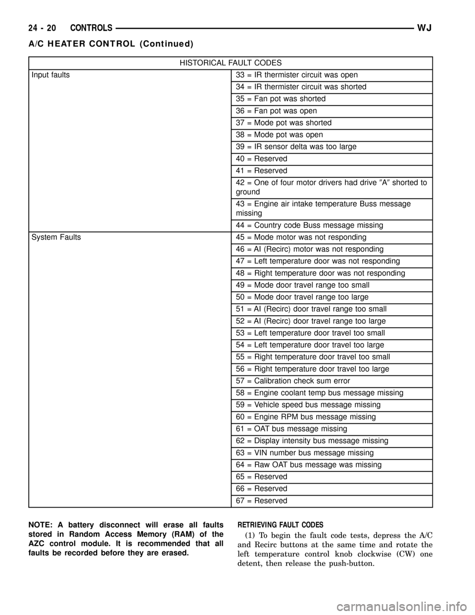
HISTORICAL FAULT CODES
Input faults 33 = IR thermister circuit was open
34 = IR thermister circuit was shorted
35 = Fan pot was shorted
36 = Fan pot was open
37 = Mode pot was shorted
38 = Mode pot was open
39 = IR sensor delta was too large
40 = Reserved
41 = Reserved
42 = One of four motor drivers had drive9A9shorted to
ground
43 = Engine air intake temperature Buss message
missing
44 = Country code Buss message missing
System Faults 45 = Mode motor was not responding
46 = AI (Recirc) motor was not responding
47 = Left temperature door was not responding
48 = Right temperature door was not responding
49 = Mode door travel range too small
50 = Mode door travel range too large
51 = AI (Recirc) door travel range too small
52 = AI (Recirc) door travel range too large
53 = Left temperature door travel too small
54 = Left temperature door travel too large
55 = Right temperature door travel too small
56 = Right temperature door travel too large
57 = Calibration check sum error
58 = Engine coolant temp bus message missing
59 = Vehicle speed bus message missing
60 = Engine RPM bus message missing
61 = OAT bus message missing
62 = Display intensity bus message missing
63 = VIN number bus message missing
64 = Raw OAT bus message was missing
65 = Reserved
66 = Reserved
67 = Reserved
NOTE: A battery disconnect will erase all faults
stored in Random Access Memory (RAM) of the
AZC control module. It is recommended that all
faults be recorded before they are erased.RETRIEVING FAULT CODES
(1) To begin the fault code tests, depress the A/C
and Recirc buttons at the same time and rotate the
left temperature control knob clockwise (CW) one
detent, then release the push-button.
24 - 20 CONTROLSWJ
A/C HEATER CONTROL (Continued)
Page 2099 of 2199

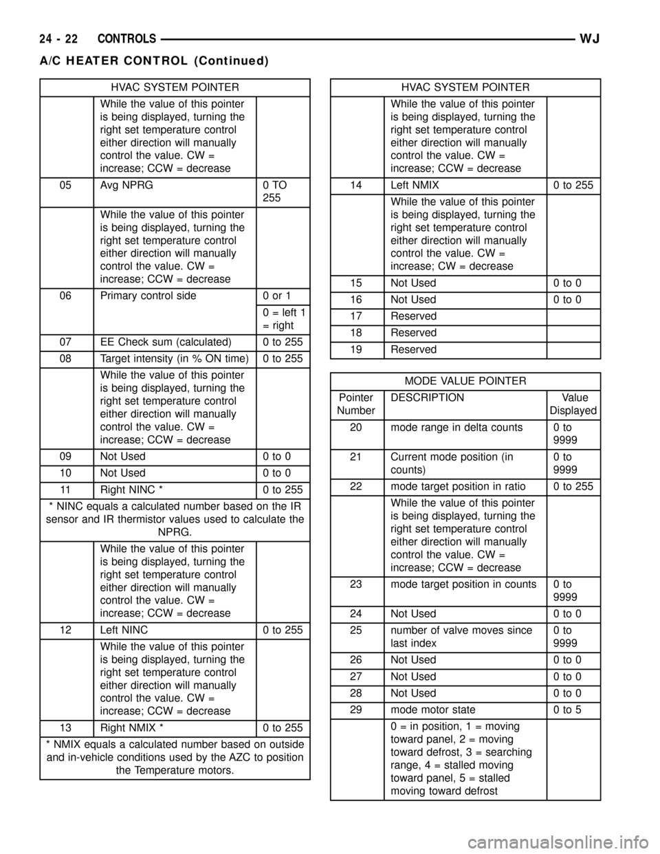
HVAC SYSTEM POINTER
While the value of this pointer
is being displayed, turning the
right set temperature control
either direction will manually
control the value. CW =
increase; CCW = decrease
05 Avg NPRG 0 TO
255
While the value of this pointer
is being displayed, turning the
right set temperature control
either direction will manually
control the value. CW =
increase; CCW = decrease
06 Primary control side 0 or 1
0 = left 1
= right
07 EE Check sum (calculated) 0 to 255
08 Target intensity (in % ON time) 0 to 255
While the value of this pointer
is being displayed, turning the
right set temperature control
either direction will manually
control the value. CW =
increase; CCW = decrease
09 Not Used 0 to 0
10 Not Used 0 to 0
11 Right NINC * 0 to 255
* NINC equals a calculated number based on the IR
sensor and IR thermistor values used to calculate the
NPRG.
While the value of this pointer
is being displayed, turning the
right set temperature control
either direction will manually
control the value. CW =
increase; CCW = decrease
12 Left NINC 0 to 255
While the value of this pointer
is being displayed, turning the
right set temperature control
either direction will manually
control the value. CW =
increase; CCW = decrease
13 Right NMIX * 0 to 255
* NMIX equals a calculated number based on outside
and in-vehicle conditions used by the AZC to position
the Temperature motors.HVAC SYSTEM POINTER
While the value of this pointer
is being displayed, turning the
right set temperature control
either direction will manually
control the value. CW =
increase; CCW = decrease
14 Left NMIX 0 to 255
While the value of this pointer
is being displayed, turning the
right set temperature control
either direction will manually
control the value. CW =
increase; CW = decrease
15 Not Used 0 to 0
16 Not Used 0 to 0
17 Reserved
18 Reserved
19 Reserved
MODE VALUE POINTER
Pointer
NumberDESCRIPTION Value
Displayed
20 mode range in delta counts 0 to
9999
21 Current mode position (in
counts)0to
9999
22 mode target position in ratio 0 to 255
While the value of this pointer
is being displayed, turning the
right set temperature control
either direction will manually
control the value. CW =
increase; CCW = decrease
23 mode target position in counts 0 to
9999
24 Not Used 0 to 0
25 number of valve moves since
last index0to
9999
26 Not Used 0 to 0
27 Not Used 0 to 0
28 Not Used 0 to 0
29 mode motor state 0 to 5
0 = in position, 1 = moving
toward panel, 2 = moving
toward defrost, 3 = searching
range, 4 = stalled moving
toward panel, 5 = stalled
moving toward defrost
24 - 22 CONTROLSWJ
A/C HEATER CONTROL (Continued)
Page 2100 of 2199

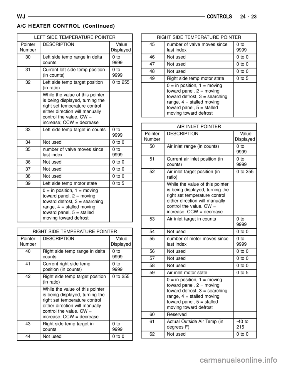
LEFT SIDE TEMPERATURE POINTER
Pointer
NumberDESCRIPTION Value
Displayed
30 Left side temp range in delta
counts0to
9999
31 Current left side temp position
(in counts)0to
9999
32 Left side temp target position
(in ratio)0to255
While the value of this pointer
is being displayed, turning the
right set temperature control
either direction will manually
control the value. CW =
increase; CCW = decrease
33 Left side temp target in counts 0 to
9999
34 Not used 0 to 0
35 number of valve moves since
last index0to
9999
36 Not used 0 to 0
37 Not used 0 to 0
38 Not used 0 to 0
39 Left side temp motor state 0 to 5
0 = in position, 1 = moving
toward panel, 2 = moving
toward defrost, 3 = searching
range, 4 = stalled moving
toward panel, 5 = stalled
moving toward defrost
RIGHT SIDE TEMPERATURE POINTER
Pointer
NumberDESCRIPTION Value
Displayed
40 Right side temp range in delta
counts0to
9999
41 Current right side temp
position (in counts)0to
9999
42 Right side temp target position
(in ratio)0to255
While the value of this pointer
is being displayed, turning the
right set temperature control
either direction will manually
control the value. CW =
increase; CCW = decrease
43 Right side temp target in
counts0to
9999
44 Not used 0 to 0
RIGHT SIDE TEMPERATURE POINTER
45 number of valve moves since
last index0to
9999
46 Not used 0 to 0
47 Not used 0 to 0
48 Not used 0 to 0
49 Right side temp motor state 0 to 5
0 = in position, 1 = moving
toward panel, 2 = moving
toward defrost, 3 = searching
range, 4 = stalled moving
toward panel, 5 = stalled
moving toward defrost
AIR INLET POINTER
Pointer
NumberDESCRIPTION Value
Displayed
50 Air inlet range (in counts) 0 to
9999
51 Current air inlet position (in
counts)0to
9999
52 Air inlet target position (in
ratio)0to255
While the value of this pointer
is being displayed, turning the
right set temperature control
either direction will manually
control the value. CW =
increase; CCW = decrease
53 Air inlet target in counts 0 to
9999
54 Not used 0 to 0
55 number of motor moves since
last index0to
9999
56 Not used 0 to 0
57 Not used 0 to 0
58 Not used 0 to 0
59 Air inlet motor state 0 to 5
0 = in position, 1 = moving
toward panel, 2 = moving
toward defrost, 3 = searching
range, 4 = stalled moving
toward panel, 5 = stalled
moving toward defrost
60 Reserved
61 Actual Outside Air Temp (in
degrees F)-40 to
215
62 Not used 0 to 0
WJCONTROLS 24 - 23
A/C HEATER CONTROL (Continued)