duct JEEP GRAND CHEROKEE 2002 WJ / 2.G Owner's Manual
[x] Cancel search | Manufacturer: JEEP, Model Year: 2002, Model line: GRAND CHEROKEE, Model: JEEP GRAND CHEROKEE 2002 WJ / 2.GPages: 2199, PDF Size: 76.01 MB
Page 234 of 2199
Carefully remove radiator pressure cap from filler
neck and check coolant level. Push down on cap to
disengage it from stop tabs. Wipe inside of filler neck
and examine lower inside sealing seat for nicks,
cracks, paint, dirt and solder residue. Inspect radia-
tor-to- reserve/overflow tank hose for internal
obstructions. Insert a wire through the hose to be
sure it is not obstructed.
Inspect cams on outside of filler neck. If cams are
damaged, seating of pressure cap valve and tester
seal will be affected.
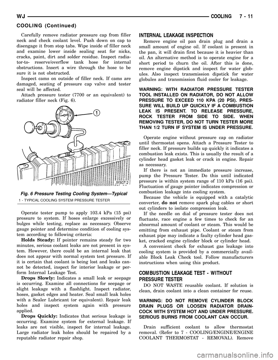
Attach pressure tester (7700 or an equivalent) to
radiator filler neck (Fig. 6).
Operate tester pump to apply 103.4 kPa (15 psi)
pressure to system. If hoses enlarge excessively or
bulges while testing, replace as necessary. Observe
gauge pointer and determine condition of cooling sys-
tem according to following criteria:
Holds Steady:If pointer remains steady for two
minutes, serious coolant leaks are not present in sys-
tem. However, there could be an internal leak that
does not appear with normal system test pressure. If
it is certain that coolant is being lost and leaks can-
not be detected, inspect for interior leakage or per-
form Internal Leakage Test.
Drops Slowly:Indicates a small leak or seepage
is occurring. Examine all connections for seepage or
slight leakage with a flashlight. Inspect radiator,
hoses, gasket edges and heater. Seal small leak holes
with a Sealer Lubricant (or equivalent). Repair leak
holes and inspect system again with pressure
applied.
Drops Quickly:Indicates that serious leakage is
occurring. Examine system for external leakage. If
leaks are not visible, inspect for internal leakage.
Large radiator leak holes should be repaired by a
reputable radiator repair shop.INTERNAL LEAKAGE INSPECTION
Remove engine oil pan drain plug and drain a
small amount of engine oil. If coolant is present in
the pan, it will drain first because it is heavier than
oil. An alternative method is to operate engine for a
short period to churn the oil. After this is done,
remove engine dipstick and inspect for water glob-
ules. Also inspect transmission dipstick for water
globules and transmission fluid cooler for leakage.
WARNING: WITH RADIATOR PRESSURE TESTER
TOOL INSTALLED ON RADIATOR, DO NOT ALLOW
PRESSURE TO EXCEED 110 KPA (20 PSI). PRES-
SURE WILL BUILD UP QUICKLY IF A COMBUSTION
LEAK IS PRESENT. TO RELEASE PRESSURE,
ROCK TESTER FROM SIDE TO SIDE. WHEN
REMOVING TESTER, DO NOT TURN TESTER MORE
THAN 1/2 TURN IF SYSTEM IS UNDER PRESSURE.
Operate engine without pressure cap on radiator
until thermostat opens. Attach a Pressure Tester to
filler neck. If pressure builds up quickly it indicates a
combustion leak exists. This is usually the result of a
cylinder head gasket leak or crack in engine. Repair
as necessary.
If there is not an immediate pressure increase,
pump the Pressure Tester. Do this until indicated
pressure is within system range of 110 kPa (16 psi).
Fluctuation of gauge pointer indicates compression or
combustion leakage into cooling system.
Because the vehicle is equipped with a catalytic
converter,do notremove spark plug cables or short
out cylinders to isolate compression leak.
If the needle on dial of pressure tester does not
fluctuate, race engine a few times to check for an
abnormal amount of coolant or steam. This would be
emitting from exhaust pipe. Coolant or steam from
exhaust pipe may indicate a faulty cylinder head gas-
ket, cracked engine cylinder block or cylinder head.
A convenient check for exhaust gas leakage into
cooling system is provided by a commercially avail-
able Block Leak Check tool. Follow manufacturers
instructions when using this product.
COMBUSTION LEAKAGE TEST - WITHOUT
PRESSURE TESTER
DO NOT WASTE reusable coolant. If solution is
clean, drain coolant into a clean container for reuse.
WARNING: DO NOT REMOVE CYLINDER BLOCK
DRAIN PLUGS OR LOOSEN RADIATOR DRAIN-
COCK WITH SYSTEM HOT AND UNDER PRESSURE.
SERIOUS BURNS FROM COOLANT CAN OCCUR.
Drain sufficient coolant to allow thermostat
removal. (Refer to 7 - COOLING/ENGINE/ENGINE
COOLANT THERMOSTAT - REMOVAL). Remove
Fig. 6 Pressure Testing Cooling SystemÐTypical
1 - TYPICAL COOLING SYSTEM PRESSURE TESTER
WJCOOLING 7 - 11
COOLING (Continued)
Page 266 of 2199
(4) Remove two radiator mounting bolts.
(5) Disconnect both transmission cooler lines from
radiator.
(6) Disconnect electrical connector for the fan con-
trol solenoid.
(7) Disconnect the power steering cooler line from
cooler and filter.
(8) Disconnect the radiator upper and lower hoses.
(9) Disconnect the overflow hose from radiator.
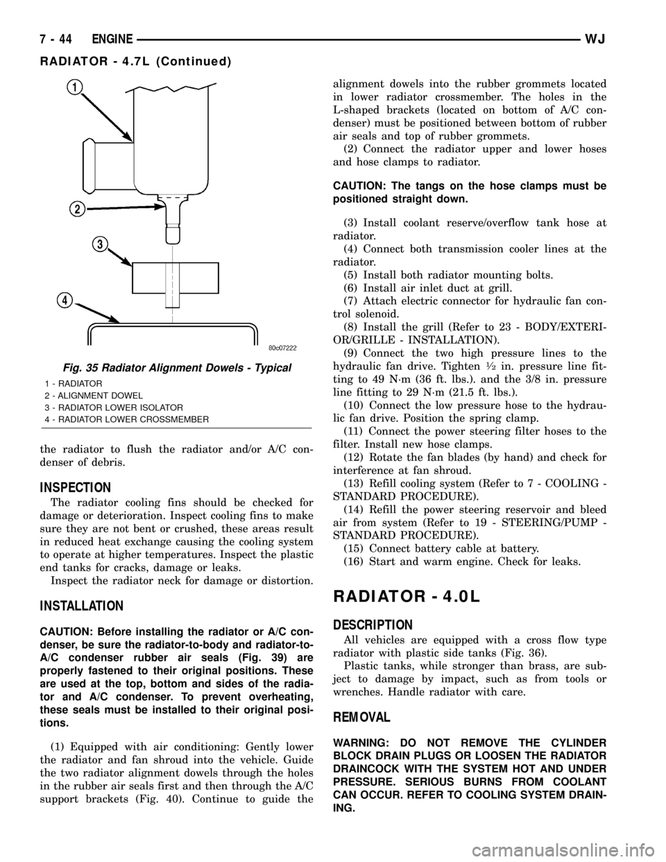
(10) Remove the air inlet duct at the grill.(11) The lower part of radiator is equipped with
two alignment dowel pins (Fig. 35). They are located
on the bottom of radiator tank and fit into rubber
grommets. These rubber grommets are pressed into
the radiator lower crossmember.
WARNING: THE AIR CONDITIONING SYSTEM (IF
EQUIPPED) IS UNDER A CONSTANT PRESSURE
EVEN WITH THE ENGINE OFF. REFER TO REFRIG-
ERANT WARNINGS IN, HEATING AND AIR CONDI-
TIONING BEFORE HANDLING ANY AIR
CONDITIONING COMPONENT.
NOTE: The radiator and radiator cooling fan can be
removed as an assembly. It is not necessary to
remove the cooling fan before removing or install-
ing the radiator.
(12) Disconnect the two high pressure fluid lines
at the hydraulic fan drive.
(13) Disconnect the low pressure return hose at
the hydraulic fan drive.
(14) Gently lift up and remove radiator from vehi-
cle. Be careful not to scrape the radiator fins against
any other component. Also be careful not to disturb
the air conditioning condenser (if equipped).
CLEANING
Clean radiator fins With the engine cold, apply cold
water and compressed air to the back (engine side) of
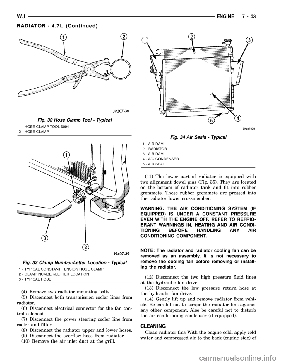
Fig. 32 Hose Clamp Tool - Typical
1 - HOSE CLAMP TOOL 6094
2 - HOSE CLAMP
Fig. 33 Clamp Number/Letter Location - Typical
1 - TYPICAL CONSTANT TENSION HOSE CLAMP
2 - CLAMP NUMBER/LETTER LOCATION
3 - TYPICAL HOSE
Fig. 34 Air Seals - Typical
1 - AIR DAM
2 - RADIATOR
3 - AIR DAM
4 - A/C CONDENSER
5 - AIR SEAL
WJENGINE 7 - 43
RADIATOR - 4.7L (Continued)
Page 267 of 2199
the radiator to flush the radiator and/or A/C con-
denser of debris.
INSPECTION
The radiator cooling fins should be checked for
damage or deterioration. Inspect cooling fins to make
sure they are not bent or crushed, these areas result
in reduced heat exchange causing the cooling system
to operate at higher temperatures. Inspect the plastic
end tanks for cracks, damage or leaks.
Inspect the radiator neck for damage or distortion.
INSTALLATION
CAUTION: Before installing the radiator or A/C con-
denser, be sure the radiator-to-body and radiator-to-
A/C condenser rubber air seals (Fig. 39) are
properly fastened to their original positions. These
are used at the top, bottom and sides of the radia-
tor and A/C condenser. To prevent overheating,
these seals must be installed to their original posi-
tions.
(1) Equipped with air conditioning: Gently lower
the radiator and fan shroud into the vehicle. Guide
the two radiator alignment dowels through the holes
in the rubber air seals first and then through the A/C
support brackets (Fig. 40). Continue to guide thealignment dowels into the rubber grommets located
in lower radiator crossmember. The holes in the
L-shaped brackets (located on bottom of A/C con-
denser) must be positioned between bottom of rubber
air seals and top of rubber grommets.
(2) Connect the radiator upper and lower hoses
and hose clamps to radiator.
CAUTION: The tangs on the hose clamps must be
positioned straight down.
(3) Install coolant reserve/overflow tank hose at
radiator.
(4) Connect both transmission cooler lines at the
radiator.
(5) Install both radiator mounting bolts.
(6) Install air inlet duct at grill.
(7) Attach electric connector for hydraulic fan con-
trol solenoid.
(8) Install the grill (Refer to 23 - BODY/EXTERI-
OR/GRILLE - INSTALLATION).
(9) Connect the two high pressure lines to the
hydraulic fan drive. Tighten
1¤2in. pressure line fit-
ting to 49 N´m (36 ft. lbs.). and the 3/8 in. pressure
line fitting to 29 N´m (21.5 ft. lbs.).
(10) Connect the low pressure hose to the hydrau-
lic fan drive. Position the spring clamp.
(11) Connect the power steering filter hoses to the
filter. Install new hose clamps.
(12) Rotate the fan blades (by hand) and check for
interference at fan shroud.
(13) Refill cooling system (Refer to 7 - COOLING -
STANDARD PROCEDURE).
(14) Refill the power steering reservoir and bleed
air from system (Refer to 19 - STEERING/PUMP -
STANDARD PROCEDURE).
(15) Connect battery cable at battery.
(16) Start and warm engine. Check for leaks.
RADIATOR - 4.0L
DESCRIPTION
All vehicles are equipped with a cross flow type
radiator with plastic side tanks (Fig. 36).
Plastic tanks, while stronger than brass, are sub-
ject to damage by impact, such as from tools or
wrenches. Handle radiator with care.
REMOVAL
WARNING: DO NOT REMOVE THE CYLINDER
BLOCK DRAIN PLUGS OR LOOSEN THE RADIATOR
DRAINCOCK WITH THE SYSTEM HOT AND UNDER
PRESSURE. SERIOUS BURNS FROM COOLANT
CAN OCCUR. REFER TO COOLING SYSTEM DRAIN-
ING.
Fig. 35 Radiator Alignment Dowels - Typical
1 - RADIATOR
2 - ALIGNMENT DOWEL
3 - RADIATOR LOWER ISOLATOR
4 - RADIATOR LOWER CROSSMEMBER
7 - 44 ENGINEWJ
RADIATOR - 4.7L (Continued)
Page 269 of 2199
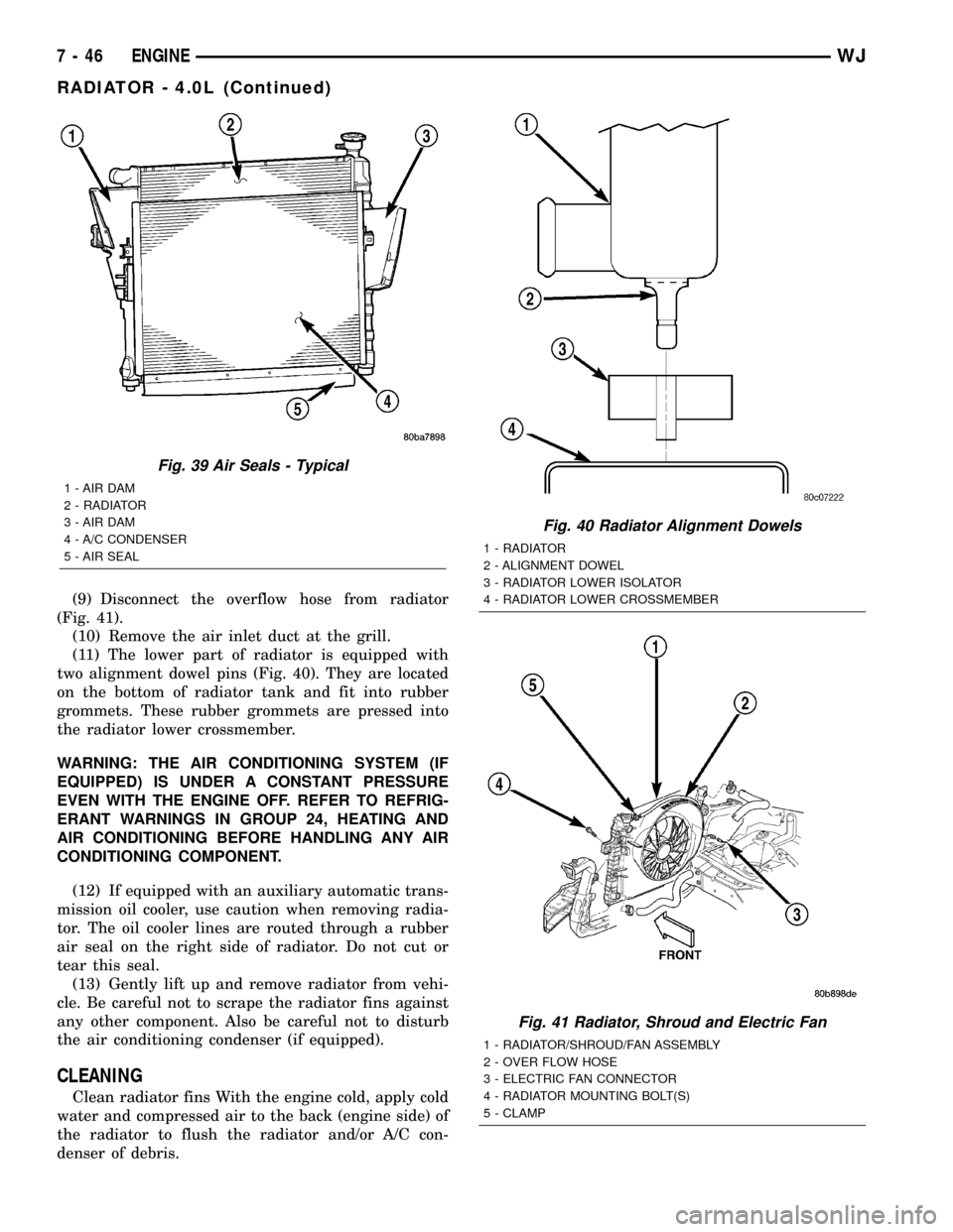
(9) Disconnect the overflow hose from radiator
(Fig. 41).
(10) Remove the air inlet duct at the grill.
(11) The lower part of radiator is equipped with
two alignment dowel pins (Fig. 40). They are located
on the bottom of radiator tank and fit into rubber
grommets. These rubber grommets are pressed into
the radiator lower crossmember.
WARNING: THE AIR CONDITIONING SYSTEM (IF
EQUIPPED) IS UNDER A CONSTANT PRESSURE
EVEN WITH THE ENGINE OFF. REFER TO REFRIG-
ERANT WARNINGS IN GROUP 24, HEATING AND
AIR CONDITIONING BEFORE HANDLING ANY AIR
CONDITIONING COMPONENT.
(12) If equipped with an auxiliary automatic trans-
mission oil cooler, use caution when removing radia-
tor. The oil cooler lines are routed through a rubber
air seal on the right side of radiator. Do not cut or
tear this seal.
(13) Gently lift up and remove radiator from vehi-
cle. Be careful not to scrape the radiator fins against
any other component. Also be careful not to disturb
the air conditioning condenser (if equipped).
CLEANING
Clean radiator fins With the engine cold, apply cold
water and compressed air to the back (engine side) of
the radiator to flush the radiator and/or A/C con-
denser of debris.
Fig. 39 Air Seals - Typical
1 - AIR DAM
2 - RADIATOR
3 - AIR DAM
4 - A/C CONDENSER
5 - AIR SEAL
Fig. 40 Radiator Alignment Dowels
1 - RADIATOR
2 - ALIGNMENT DOWEL
3 - RADIATOR LOWER ISOLATOR
4 - RADIATOR LOWER CROSSMEMBER
Fig. 41 Radiator, Shroud and Electric Fan
1 - RADIATOR/SHROUD/FAN ASSEMBLY
2 - OVER FLOW HOSE
3 - ELECTRIC FAN CONNECTOR
4 - RADIATOR MOUNTING BOLT(S)
5 - CLAMP
7 - 46 ENGINEWJ
RADIATOR - 4.0L (Continued)
Page 270 of 2199

INSPECTION
The radiator cooling fins should be checked for
damage or deterioration. Inspect cooling fins to make
sure they are not bent or crushed, these areas result
in reduced heat exchange causing the cooling system
to operate at higher temperatures. Inspect the plastic
end tanks for cracks, damage or leaks.
Inspect the radiator neck for damage or distortion.
INSTALLATION
CAUTION: Before installing the radiator or A/C con-
denser, be sure the radiator-to-body and radiator-to-
A/C condenser rubber air seals (Fig. 39) are
properly fastened to their original positions. These
are used at the top, bottom and sides of the radia-
tor and A/C condenser. To prevent overheating,
these seals must be installed to their original posi-
tions.
(1) Equipped with air conditioning: Gently lower
the radiator into the vehicle. Guide the two radiator
alignment dowels through the holes in the rubber air
seals first and then through the A/C support brackets
(Fig. 40). Continue to guide the alignment dowels
into the rubber grommets located in lower radiator
crossmember. The holes in the L-shaped brackets
(located on bottom of A/C condenser) must be posi-
tioned between bottom of rubber air seals and top of
rubber grommets.
(2) Connect the radiator upper and lower hoses
and hose clamps to radiator (Fig. 41).
CAUTION: The tangs on the hose clamps must be
positioned straight down.
(3) Install coolant reserve/overflow tank hose at
radiator (Fig. 41).
(4) Connect both transmission cooler lines at the
radiator (Fig. 41).
(5) Install both radiator mounting bolts (Fig. 41).
(6) Install air inlet duct at grill.
(7) Attach electric fan harness to shroud, then con-
nect harness to connector (Fig. 41).
(8) Install the grill (Refer to 23 - BODY/EXTERI-
OR/GRILLE - INSTALLATION).
(9) Install the fan/viscous fan drive assembly to
the water pump.
(10) Rotate the fan blades (by hand) and check for
interference at fan shroud.
(11) Be sure of at least 25 mm (1.0 inch) between
tips of fan blades and fan shroud.
(12) Fill cooling system (Refer to 7 - COOLING -
STANDARD PROCEDURE).
(13) Connect battery cable at battery.
(14) Start and warm engine. Check for leaks.
RADIATOR FAN MOTOR
DIAGNOSIS AND TESTINGÐELECTRIC
COOLING FAN
The powertrain control module (PCM) will enter a
diagnostic trouble code (DTC) in memory if it detects
a problem in the auxiliary cooling fan relay or circuit.
(Refer to 25 - EMISSIONS CONTROL - DESCRIP-
TION).
If the electric cooling fan is inoperative, check the
15A fuse in the junction block and the 40A fuse in
the Power Distribution Center (PDC) with a 12 volt
test lamp or DVOM. Refer to the inside of the PDC
cover for the exact location of the fuse. If fuses are
okay, refer to ELECTRICAL for cooling fan and relay
circuit schematic.
WATER PUMP - 4.7L
DESCRIPTION
DESCRIPTIONÐWATER PUMP
A centrifugal water pump circulates coolant
through the water jackets, passages, intake manifold,
radiator core, cooling system hoses and heater core.
The pump is driven from the engine crankshaft by a
single serpentine drive belt.
The water pump impeller is pressed onto the rear
of a shaft that rotates in bearings pressed into the
housing. The housing has two small holes to allow
seepage to escape. The water pump seals are lubri-
cated by the antifreeze in the coolant mixture. No
additional lubrication is necessary.
Both heater hoses are connected to fittings on the
timing chain front cover. The water pump is also
mounted directly to the timing chain cover and is
equipped with a non serviceable integral pulley (Fig.
42).
DESCRIPTIONÐWATER PUMP BYPASS
The 4.7L engine uses an internal water/coolant
bypass system. The design uses galleries in the tim-
ing chain cover to circulate coolant during engine
warm-up preventing the coolant from flowing
through the radiator. The thermostat uses a stub
shaft located at the rear of the thermostat (Fig. 43)
to control flow through the bypass gallery.
OPERATION
OPERATIONÐWATER PUMP
A centrifugal water pump circulates coolant
through the water jackets, passages, intake manifold,
WJENGINE 7 - 47
RADIATOR - 4.0L (Continued)
Page 282 of 2199

OPERATION
The audio system components are designed to pro-
vide audio entertainment and information through
the reception, tuning and amplification of locally
broadcast radio signals in both the Amplitude Modu-
lating (AM) and Frequency Modulating (FM) com-
mercial frequency ranges. Electromagnetic radio
signals that are broadcast from a radio station
induce electrical modulations into the audio system
antenna mast. The antenna body and cable conduct
these weak signals from the antenna mast to the
radio. The radio then tunes and amplifies these weak
radio frequency signals into stronger electrical audio
signals that are required in order to operate the
audio system speakers. The speakers convert these
electrical signals into air movement, which repro-
duces the sounds being broadcast by the radio sta-
tion.
Some audio systems also offer the user the option
of selecting from and listening to prerecorded audio
cassette tapes, audio compact discs, or both. Regard-
less of the media type, the audio system components
provide the user with the ability to electronically
amplify and adjust the audio signals being repro-
duced by the speakers within the vehicle to suit the
preferences of the vehicle occupants.
The audio system components operate on battery
current received through a fuse in the Junction Block
(JB) on a fused ignition switch output (run-acc) cir-
cuit so that the system will only operate when the
ignition switch is in the On or Accessory positions.
On vehicles that are equipped with the optional
remote radio switches, the BCM receives hard wired
resistor multiplexed inputs from the remote radio
switches. The programming in the BCM allows it to
process those inputs and send the proper messages to
the radio receiver over the PCI data bus to control
the radio volume up or down, station seek up or
down, preset station advance, and mode advance
functions.On vehicles equipped with the optional memory
system, when the DDM receives a Driver 1 or Driver
2 memory recall input from the memory switch on
the driver side front door trim panel or a memory
recall message from the Remote Keyless Entry (RKE)
receiver in the PDM, the DDM sends a memory
recall message back to the radio receiver over the
PCI data bus to recall the radio station presets and
last station listened to information.
See the owner's manual in the vehicle glove box for
more information on the features, use and operation
of each of the available audio systems.
DIAGNOSIS AND TESTING - AUDIO
Any diagnosis of the Audio system should
begin with the use of the DRB IIItdiagnostic
tool. For information on the use of the DRB
IIIt, refer to the appropriate Diagnostic Service
Manual.
Refer to the appropriate wiring information. The
wiring information includes wiring diagrams, proper
wire and connector repair procedures, details of wire
harness routing and retention, connector pin-out
information and location views for the various wire
harness connectors, splices and grounds.
WARNING: DISABLE THE AIRBAG SYSTEM
BEFORE ATTEMPTING ANY STEERING WHEEL,
STEERING COLUMN, SEAT BELT TENSIONER, SIDE
AIRBAG, OR INSTRUMENT PANEL COMPONENT
DIAGNOSIS OR SERVICE. DISCONNECT AND ISO-
LATE THE BATTERY NEGATIVE (GROUND) CABLE,
THEN WAIT TWO MINUTES FOR THE AIRBAG SYS-
TEM CAPACITOR TO DISCHARGE BEFORE PER-
FORMING FURTHER DIAGNOSIS OR SERVICE. THIS
IS THE ONLY SURE WAY TO DISABLE THE AIRBAG
SYSTEM. FAILURE TO TAKE THE PROPER PRE-
CAUTIONS COULD RESULT IN ACCIDENTAL AIR-
BAG DEPLOYMENT AND POSSIBLE PERSONAL
INJURY.
WJAUDIO 8A - 3
AUDIO (Continued)
Page 286 of 2199
ANTENNA BODY & CABLE
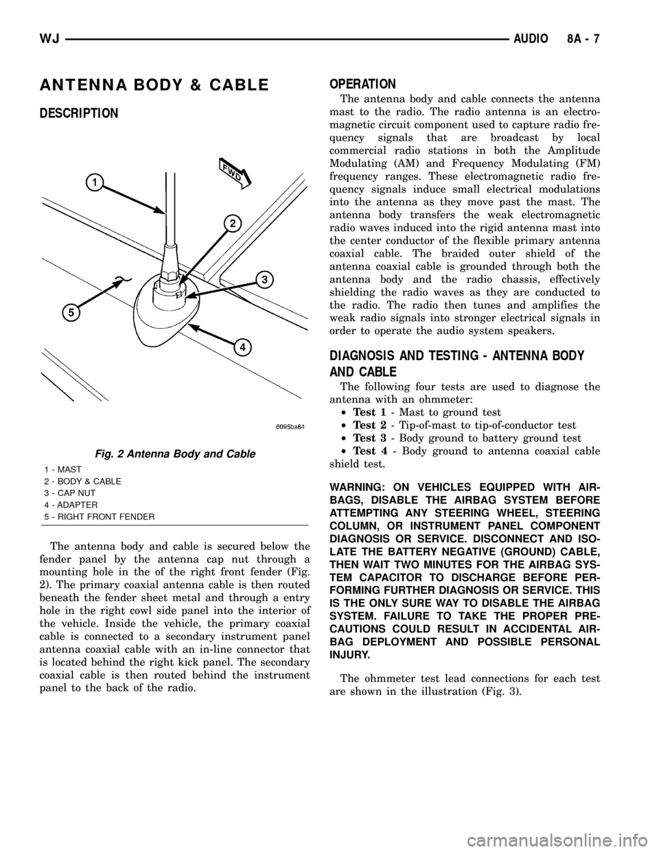
DESCRIPTION
The antenna body and cable is secured below the
fender panel by the antenna cap nut through a
mounting hole in the of the right front fender (Fig.
2). The primary coaxial antenna cable is then routed
beneath the fender sheet metal and through a entry
hole in the right cowl side panel into the interior of
the vehicle. Inside the vehicle, the primary coaxial
cable is connected to a secondary instrument panel
antenna coaxial cable with an in-line connector that
is located behind the right kick panel. The secondary
coaxial cable is then routed behind the instrument
panel to the back of the radio.
OPERATION
The antenna body and cable connects the antenna
mast to the radio. The radio antenna is an electro-
magnetic circuit component used to capture radio fre-
quency signals that are broadcast by local
commercial radio stations in both the Amplitude
Modulating (AM) and Frequency Modulating (FM)
frequency ranges. These electromagnetic radio fre-
quency signals induce small electrical modulations
into the antenna as they move past the mast. The
antenna body transfers the weak electromagnetic
radio waves induced into the rigid antenna mast into
the center conductor of the flexible primary antenna
coaxial cable. The braided outer shield of the
antenna coaxial cable is grounded through both the
antenna body and the radio chassis, effectively
shielding the radio waves as they are conducted to
the radio. The radio then tunes and amplifies the
weak radio signals into stronger electrical signals in
order to operate the audio system speakers.
DIAGNOSIS AND TESTING - ANTENNA BODY
AND CABLE
The following four tests are used to diagnose the
antenna with an ohmmeter:
²Test 1- Mast to ground test
²Test 2- Tip-of-mast to tip-of-conductor test
²Test 3- Body ground to battery ground test
²Test 4- Body ground to antenna coaxial cable
shield test.
WARNING: ON VEHICLES EQUIPPED WITH AIR-
BAGS, DISABLE THE AIRBAG SYSTEM BEFORE
ATTEMPTING ANY STEERING WHEEL, STEERING
COLUMN, OR INSTRUMENT PANEL COMPONENT
DIAGNOSIS OR SERVICE. DISCONNECT AND ISO-
LATE THE BATTERY NEGATIVE (GROUND) CABLE,
THEN WAIT TWO MINUTES FOR THE AIRBAG SYS-
TEM CAPACITOR TO DISCHARGE BEFORE PER-
FORMING FURTHER DIAGNOSIS OR SERVICE. THIS
IS THE ONLY SURE WAY TO DISABLE THE AIRBAG
SYSTEM. FAILURE TO TAKE THE PROPER PRE-
CAUTIONS COULD RESULT IN ACCIDENTAL AIR-
BAG DEPLOYMENT AND POSSIBLE PERSONAL
INJURY.
The ohmmeter test lead connections for each test
are shown in the illustration (Fig. 3).
Fig. 2 Antenna Body and Cable
1 - MAST
2 - BODY & CABLE
3 - CAP NUT
4 - ADAPTER
5 - RIGHT FRONT FENDER
WJAUDIO 8A - 7
Page 287 of 2199

NOTE: This model has a two-piece antenna coaxial
cable. Tests 2 and 4 must be conducted in two
steps to isolate an antenna cable problem. First,
test the primary antenna cable (integral to the
antenna body and cable) from the coaxial cable
connector under the right end of the instrument
panel near the right cowl side inner panel to the
antenna body. Then, test the secondary antenna
cable (instrument panel antenna cable) from the
coaxial cable connector under the right end of the
instrument panel near the right cowl side inner
panel to the coaxial cable connector at the radio.
NOTE: Use extreme caution when checking continu-
ity of center conductor to avoid damage.
TEST 1
Test 1 determines if the antenna mast is insulated
from ground. Proceed as follows:
(1) Disconnect and isolate the antenna coaxial
cable connector under the right end of the instru-
ment panel near the right cowl side inner panel.
(2) Touch one ohmmeter test lead to the tip of the
antenna mast. Touch the other test lead to the
antenna cap nut. Check the ohmmeter reading for
continuity.
(3) There should be no continuity. If OK, go to Test
2. If not OK, replace the faulty antenna body and
cable.
TEST 2
Test 2 checks the antenna conductor components
for an open circuit. This test should be performed
first on the entire antenna circuit, from the antennamast to the center conductor of the coaxial cable con-
nector at the radio. If an open circuit is detected,
each of the three antenna conductor components
(antenna mast, antenna body and primary cable unit,
instrument panel antenna secondary cable) should be
isolated and tested individually to locate the exact
component that is the source of the open circuit. To
begin this test, proceed as follows:
(1) Disconnect the instrument panel (secondary)
antenna cable coaxial connector from the back of the
radio.
(2) Touch one ohmmeter test lead to the tip of the
antenna mast. Touch the other test lead to the center
conductor pin of the instrument panel antenna cable
coaxial connector for the radio. Check the ohmmeter
reading for continuity.
(3) There should be continuity. The ohmmeter
should register only a fraction of an ohm resistance.
High or infinite resistance indicates a damaged or
open antenna conductor. If OK, go to Test 3. If not
OK, isolate and test each of the individual antenna
conductor components. Replace only the faulty
antenna conductor component.
TEST 3
Test 3 checks the condition of the vehicle body
ground connection. To begin this test, proceed as fol-
lows:
(1) This test must be performed with the battery
positive cable disconnected from the battery. Discon-
nect and isolate both battery cables, negative cable
first.
(2) Reconnect the battery negative cable.
(3) Touch one ohmmeter test lead to a good clean
ground point on the vehicle fender. Touch the other
test lead to the battery negative terminal post. Check
the ohmmeter reading for continuity.
(4) There should be continuity. The ohmmeter
should register less than one ohm resistance. High or
infinite resistance indicates a loose, corroded, or
damaged connection between the battery negative
terminal and the vehicle body. If OK, go to Test 4. If
not OK, check the battery negative cable connection
to the vehicle body and the radio noise suppression
ground strap connections to the engine and the vehi-
cle body for being loose or corroded. Clean or tighten
these connections as required.
TEST 4
Test 4 checks the condition of the connection
between the antenna coaxial cable shield and the
vehicle body ground as follows:
(1) Disconnect and isolate the antenna coaxial
cable connector under the right end of the instru-
ment panel near the right cowl side inner panel.
Fig. 3 Antenna Tests - Typical
8A - 8 AUDIOWJ
ANTENNA BODY & CABLE (Continued)
Page 294 of 2199
(2) Install the four mounting nuts. Tighten the
nuts to 12 N´m (105 in. lbs.).
(3) Reconnect the right body wire harness connec-
tor.
(4) Position the compact disc changer storage bin
onto the right side quarter trim panel.
(5) Using both hands push the compact disc
changer storage bin firmly and evenly toward the
right side quarter trim panel far enough to engage
the hooks on the bin with the slots in the panel.
(6) Using both hands push the compact disc
changer storage bin firmly and evenly downward far
enough to align the screw holes in the bin with the
mounting holes in the right side quarter trim panel.
(7) Install the two screws that secure the top of
the compact disc changer storage bin. Tighten the
screws to 1.7 N´m (15 in. lbs.).
(8) Reconnect the battery negative cable.
INSTRUMENT PANEL
ANTENNA CABLE
REMOVAL
WARNING: ON VEHICLES EQUIPPED WITH AIR-
BAGS, REFER TO ELECTRICAL, RESTRAINTS
BEFORE ATTEMPTING ANY STEERING WHEEL,
STEERING COLUMN, OR INSTRUMENT PANEL
COMPONENT DIAGNOSIS OR SERVICE. FAILURE
TO TAKE THE PROPER PRECAUTIONS COULD
RESULT IN ACCIDENTAL AIRBAG DEPLOYMENT
AND POSSIBLE PERSONAL INJURY.
(1) Disconnect and isolate the battery negative
cable.
(2) Remove the scuff plate from the right front
door sill. (Refer to 23 - BODY/INTERIOR/DOOR
SILL SCUFF PLATE - REMOVAL) for the proce-
dures.
(3) Remove the trim panel from the right inner
cowl side. (Refer to 23 - BODY/INTERIOR/COWL
TRIM - REMOVAL) for the procedures.
(4) Reach under the passenger side of the instru-
ment panel near the right cowl side inner panel to
disconnect the antenna coaxial cable connector by
pulling it apart while twisting the metal connector
halves. Do not pull on the cable.
(5) Disengage the antenna cable retainer from the
mounting hole in the wire harness mounting tab
under the passenger side end of the instrument
panel.
(6) Remove the radio receiver from the instrument
panel. (Refer to 8 - ELECTRICAL/AUDIO/RADIO -
REMOVAL) for the procedures.(7) Remove the passenger side airbag module from
the instrument panel. (Refer to 8 - ELECTRICAL/
RESTRAINTS/PASSENGER AIRBAG - REMOVAL)
for the procedures.
(8) Disengage the antenna cable retainer from the
mounting hole in the top of the radio mount on the
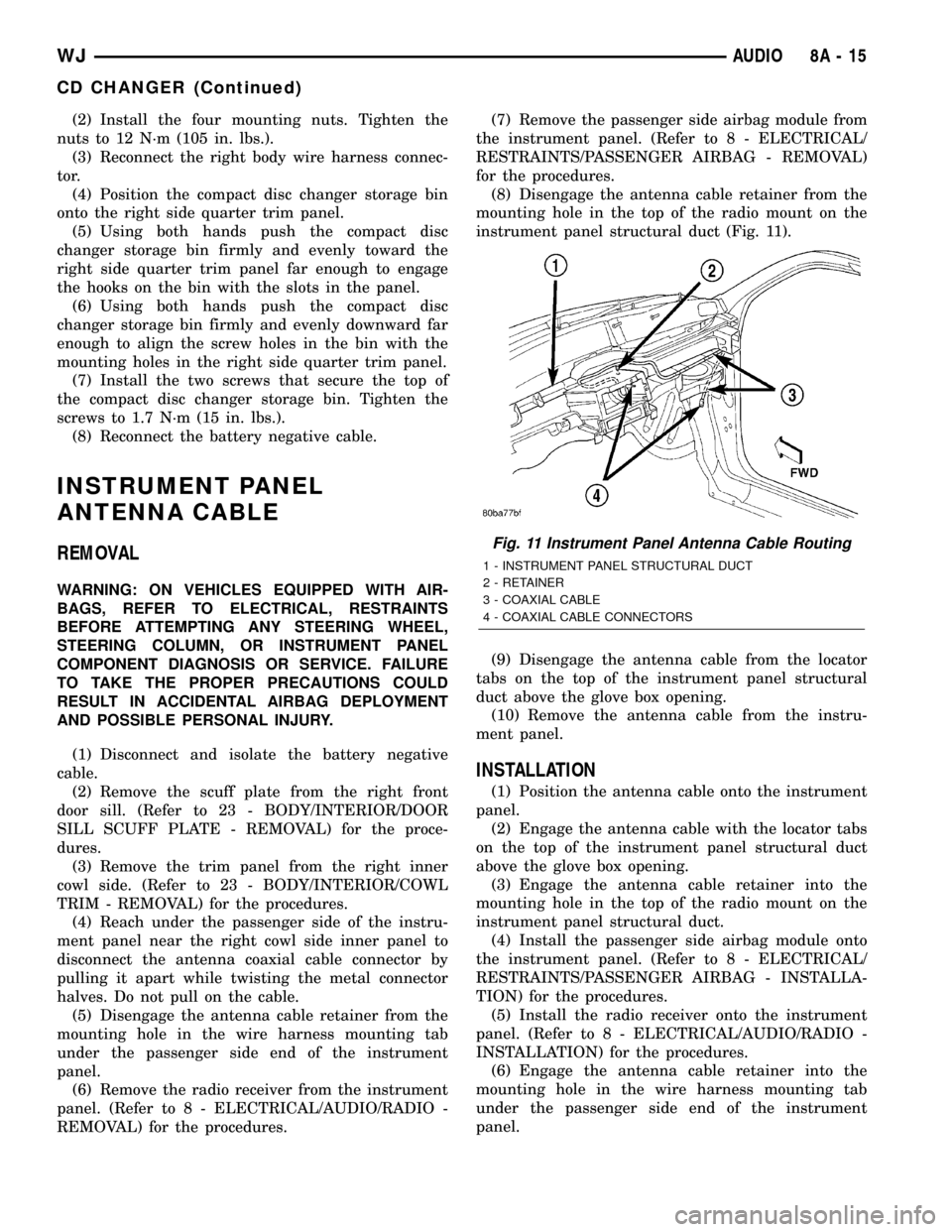
instrument panel structural duct (Fig. 11).
(9) Disengage the antenna cable from the locator
tabs on the top of the instrument panel structural
duct above the glove box opening.
(10) Remove the antenna cable from the instru-
ment panel.
INSTALLATION
(1) Position the antenna cable onto the instrument
panel.
(2) Engage the antenna cable with the locator tabs
on the top of the instrument panel structural duct
above the glove box opening.
(3) Engage the antenna cable retainer into the
mounting hole in the top of the radio mount on the
instrument panel structural duct.
(4) Install the passenger side airbag module onto
the instrument panel. (Refer to 8 - ELECTRICAL/
RESTRAINTS/PASSENGER AIRBAG - INSTALLA-
TION) for the procedures.
(5) Install the radio receiver onto the instrument
panel. (Refer to 8 - ELECTRICAL/AUDIO/RADIO -
INSTALLATION) for the procedures.
(6) Engage the antenna cable retainer into the
mounting hole in the wire harness mounting tab
under the passenger side end of the instrument
panel.
Fig. 11 Instrument Panel Antenna Cable Routing
1 - INSTRUMENT PANEL STRUCTURAL DUCT
2 - RETAINER
3 - COAXIAL CABLE
4 - COAXIAL CABLE CONNECTORS
WJAUDIO 8A - 15
CD CHANGER (Continued)
Page 329 of 2199

²Pressure Switches
²Transmission Temperature Sensor
²Input Shaft Speed Sensor
²Output Shaft Speed Sensor
²Line Pressure Sensor
Some examples ofindirect inputsto the TCM
are:
²Engine/Body Identification
²Manifold Pressure
²Target Idle
²Torque Reduction Confirmation
²Engine Coolant Temperature
²Ambient/Battery Temperature
²DRBtScan Tool Communication
Based on the information received from these var-
ious inputs, the TCM determines the appropriate
shift schedule and shift points, depending on the
present operating conditions and driver demand.
This is possible through the control of various direct
and indirect outputs.
Some examples of TCMdirect outputsare:
²Transmission Control Relay
²Solenoids
²Torque Reduction Request
Some examples of TCMindirect outputsare:
²Transmission Temperature (to PCM)
²PRNDL Position (to BCM)
In addition to monitoring inputs and controlling
outputs, the TCM has other important responsibili-
ties and functions:
²Storing and maintaining Clutch Volume Indexes
(CVI)
²Storing and selecting appropriate Shift Sched-
ules
²System self-diagnostics
²Diagnostic capabilities (with DRBtscan tool)
NOTE: If the TCM has been replaced, the ªQuick
Learn Procedureº must be performed. (Refer to 8 -
ELECTRICAL/ELECTRONIC CONTROL MODULES/
TRANSMISSION CONTROL MODULE - STANDARD
PROCEDURE)
BATTERY FEED
A fused, direct battery feed to the TCM is used for
continuous power. This battery voltage is necessary
to retain adaptive learn values in the TCM's RAM
(Random Access Memory). When the battery (B+) is
disconnected, this memory is lost. When the battery
(B+) is restored, this memory loss is detected by the
TCM and a Diagnostic Trouble Code (DTC) is set.
CLUTCH VOLUME INDEXES (CVI)
An important function of the TCM is to monitor
Clutch Volume Indexes (CVI). CVIs represent the vol-
ume of fluid needed to compress a clutch pack.The TCM monitors gear ratio changes by monitor-
ing the Input and Output Speed Sensors. The Input,
or Turbine Speed Sensor sends an electrical signal to
the TCM that represents input shaft rpm. The Out-
put Speed Sensor provides the TCM with output
shaft speed information.
By comparing the two inputs, the TCM can deter-
mine transmission gear position. This is important to
the CVI calculation because the TCM determines
CVIs by monitoring how long it takes for a gear
change to occur (Fig. 18).
Gear ratios can be determined by using the
DRBIIItScan Tool and reading the Input/Output
Speed Sensor values in the ªMonitorsº display. Gear
ratio can be obtained by dividing the Input Speed
Sensor value by the Output Speed Sensor value.
The gear ratio changes as clutches are applied and
released. By monitoring the length of time it takes
for the gear ratio to change following a shift request,
the TCM can determine the volume of fluid used to
apply or release a friction element.
The volume of transmission fluid needed to apply
the friction elements are continuously updated for
adaptive controls. As friction material wears, the vol-
ume of fluid need to apply the element increases.
Fig. 18 Example of CVI Calculation
1 - OUTPUT SPEED SENSOR
2 - OUTPUT SHAFT
3 - CLUTCH PACK
4 - SEPARATOR PLATE
5 - FRICTION DISCS
6 - INPUT SHAFT
7 - INPUT SPEED SENSOR
8 - PISTON AND SEAL
8E - 20 ELECTRONIC CONTROL MODULESWJ
TRANSMISSION CONTROL MODULE (Continued)