steering gear JEEP GRAND CHEROKEE 2002 WJ / 2.G Repair Manual
[x] Cancel search | Manufacturer: JEEP, Model Year: 2002, Model line: GRAND CHEROKEE, Model: JEEP GRAND CHEROKEE 2002 WJ / 2.GPages: 2199, PDF Size: 76.01 MB
Page 1746 of 2199

ADJUSTMENTS - BRAKE TRANSMISSION
SHIFT INTERLOCK
The park interlock cable is part of the brake/shift
lever interlock system. Correct cable adjustment is
important to proper interlock operation. The gear
shift and park lock cables must both be correctly
adjusted in order to shift out of PARK.
ADJUSTMENT PROCEDURE
(1) Remove floor console as necessary for access to
the brake transmission shift interlock cable. (Refer to
23 - BODY/INTERIOR/FLOOR CONSOLE -
REMOVAL)
(2) Shift the transmission into the PARK position.
(3) Turn ignition switch to LOCK position.Be
sure ignition key cylinder is in the LOCK posi-
tion. Cable will not adjust correctly in any
other position.
(4) Pull cable lock button up to release cable (Fig.
58).
(5) Ensure that the cable is free to self-adjust by
pushing cable rearward and releasing.
(6) Push lock button down until it snaps in place.
BTSI FUNCTION CHECK
(1) Verify removal of ignition key allowed in PARK
position only.
(2) When the shift lever is in PARK, and the shift
handle push-button is in the out position, the igni-
tion key cylinder should rotate freely from off to lock.
When the shifter is in any other position, the ignition
key should not rotate from off to lock.
(3) Shifting out of PARK should be possible when
the ignition key cylinder is in the off position.
(4) Shifting out of PARK should not be possible
while applying normal push-button force, and igni-
tion key cylinder is in the run or start positions,
unless the foot brake pedal is depressed approxi-
mately 1/2 inch (12mm).
(5) Shifting out of PARK should not be possible
when the ignition key cylinder is in the accessory or
lock position.
(6) Shifting between any gear and NEUTRAL, or
PARK, may be done without depressing foot brake
with ignition switch in run or start positions.
(7) The floor shifter lever and gate positions
should be in alignment with all transmission detent
positions.
Fig. 58 Brake Transmission Shift Interlock Cable
1 - SHIFT MECHANISM 4 - STEERING COLUMN ASSEMBLY
2 - SHIFTER BTSI LEVER 5 - INTERLOCK CABLE
3 - ADJUSTMENT CLIP
WJAUTOMATIC TRANSMISSION - 545RFE 21 - 227
BRAKE TRANSMISSION SHIFT INTERLOCK MECHANISM (Continued)
Page 1774 of 2199

PARK LOCK CABLE
REMOVAL
(1) Place the shifter in the PARK position.
(2) Lower the steering column cover.
(3) With the ignition switch in the ªRUNº position
depress the park lock cable locking tab, located on
top of the cable connector at the steering column and
pull the park lock cable straight out.
(4) Remove the park lock cable from steering col-
umn (Fig. 97).
(5) Remove the floor console and related trim.
(Refer to 23 - BODY/INTERIOR/FLOOR CONSOLE -
REMOVAL)
(6) Disconnect the park lock cable from the shift
BTSI lever and remove the cable from the shifter
assembly bracket.
(7) Release the park lock cable from any remaining
clips.
(8) Remove park lock cable from the vehicle.
INSTALLATION
NOTE: The gearshift cable must be secured into
position and properly adjusted before the installa-
tion of the Park Lock Cable.
(1) Verify that the shifter is in the PARK position.
(2) Push the park lock cable straight into the
square mounting hole in the steering column until
cable snaps in place.
(3) Route park lock cable to the shifter mecha-
nism.
(4) Install the park lock cable end fitting into
shifter BTSI lever.
(5) Pull rearward on the cable housing to snap
park lock cable adjuster ears into floor shifter
bracket.
(6) Place the ignition key cylinder in the ACCES-
SORY position.
(7) Push the cable adjuster lock clamp downward
to lock it.
(8) Test the park lock cable operation.
(9) Install the floor console and related trim.
(Refer to 23 - BODY/INTERIOR/FLOOR CONSOLE -
INSTALLATION)
Fig. 97 Brake Transmission Shift Interlock
1 - SHIFT MECHANISM 4 - STEERING COLUMN ASSEMBLY
2 - SHIFTER BTSI LEVER 5 - INTERLOCK CABLE
3 - ADJUSTMENT CLIP
WJAUTOMATIC TRANSMISSION - 545RFE 21 - 255
Page 2027 of 2199

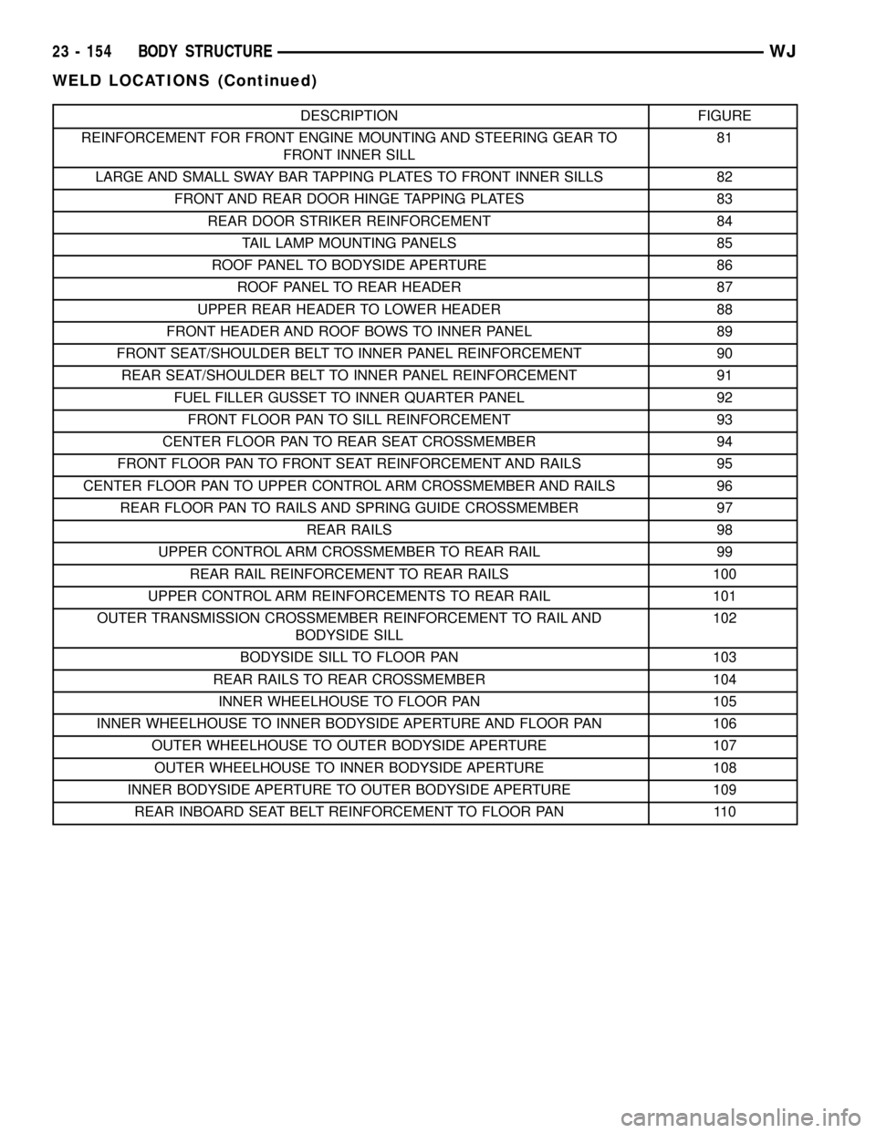
DESCRIPTION FIGURE
REINFORCEMENT FOR FRONT ENGINE MOUNTING AND STEERING GEAR TO
FRONT INNER SILL81
LARGE AND SMALL SWAY BAR TAPPING PLATES TO FRONT INNER SILLS 82
FRONT AND REAR DOOR HINGE TAPPING PLATES 83
REAR DOOR STRIKER REINFORCEMENT 84
TAIL LAMP MOUNTING PANELS 85
ROOF PANEL TO BODYSIDE APERTURE 86
ROOF PANEL TO REAR HEADER 87
UPPER REAR HEADER TO LOWER HEADER 88
FRONT HEADER AND ROOF BOWS TO INNER PANEL 89
FRONT SEAT/SHOULDER BELT TO INNER PANEL REINFORCEMENT 90
REAR SEAT/SHOULDER BELT TO INNER PANEL REINFORCEMENT 91
FUEL FILLER GUSSET TO INNER QUARTER PANEL 92
FRONT FLOOR PAN TO SILL REINFORCEMENT 93
CENTER FLOOR PAN TO REAR SEAT CROSSMEMBER 94
FRONT FLOOR PAN TO FRONT SEAT REINFORCEMENT AND RAILS 95
CENTER FLOOR PAN TO UPPER CONTROL ARM CROSSMEMBER AND RAILS 96
REAR FLOOR PAN TO RAILS AND SPRING GUIDE CROSSMEMBER 97
REAR RAILS 98
UPPER CONTROL ARM CROSSMEMBER TO REAR RAIL 99
REAR RAIL REINFORCEMENT TO REAR RAILS 100
UPPER CONTROL ARM REINFORCEMENTS TO REAR RAIL 101
OUTER TRANSMISSION CROSSMEMBER REINFORCEMENT TO RAIL AND
BODYSIDE SILL102
BODYSIDE SILL TO FLOOR PAN 103
REAR RAILS TO REAR CROSSMEMBER 104
INNER WHEELHOUSE TO FLOOR PAN 105
INNER WHEELHOUSE TO INNER BODYSIDE APERTURE AND FLOOR PAN 106
OUTER WHEELHOUSE TO OUTER BODYSIDE APERTURE 107
OUTER WHEELHOUSE TO INNER BODYSIDE APERTURE 108
INNER BODYSIDE APERTURE TO OUTER BODYSIDE APERTURE 109
REAR INBOARD SEAT BELT REINFORCEMENT TO FLOOR PAN 110
23 - 154 BODY STRUCTUREWJ
WELD LOCATIONS (Continued)
Page 2053 of 2199

Fig. 81 REINFORCEMENT FOR FRONT ENGINE MOUNTING AND STEERING GEAR TO FRONT INNER SILL
23 - 180 BODY STRUCTUREWJ
WELD LOCATIONS (Continued)