engine pressure JEEP GRAND CHEROKEE 2003 WJ / 2.G Manual PDF
[x] Cancel search | Manufacturer: JEEP, Model Year: 2003, Model line: GRAND CHEROKEE, Model: JEEP GRAND CHEROKEE 2003 WJ / 2.GPages: 2199, PDF Size: 76.01 MB
Page 1177 of 2199
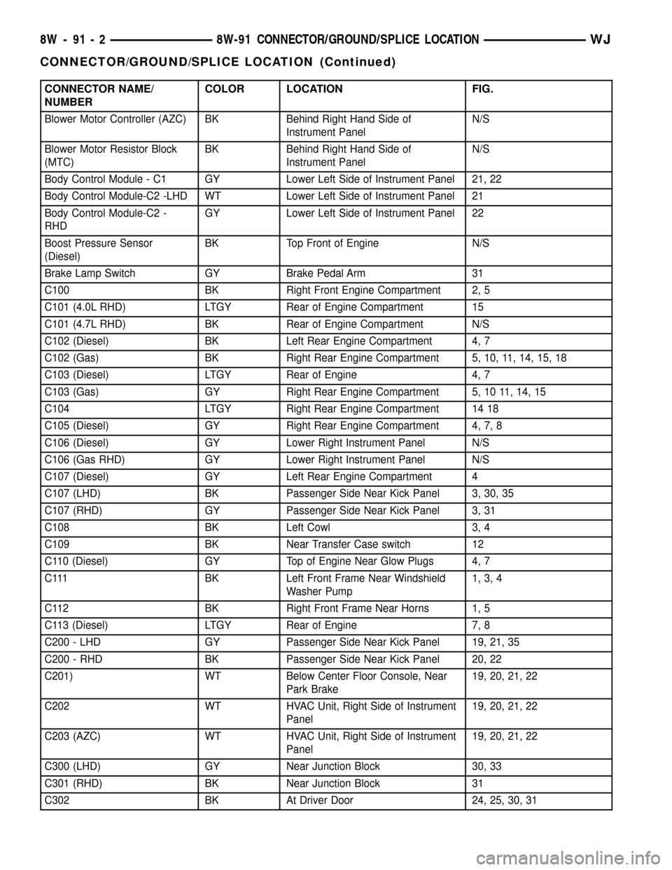
CONNECTOR NAME/
NUMBERCOLOR LOCATION FIG.
Blower Motor Controller (AZC) BK Behind Right Hand Side of
Instrument PanelN/S
Blower Motor Resistor Block
(MTC)BK Behind Right Hand Side of
Instrument PanelN/S
Body Control Module - C1 GY Lower Left Side of Instrument Panel 21, 22
Body Control Module-C2 -LHD WT Lower Left Side of Instrument Panel 21
Body Control Module-C2 -
RHDGY Lower Left Side of Instrument Panel 22
Boost Pressure Sensor
(Diesel)BK Top Front of Engine N/S
Brake Lamp Switch GY Brake Pedal Arm 31
C100 BK Right Front Engine Compartment 2, 5
C101 (4.0L RHD) LTGY Rear of Engine Compartment 15
C101 (4.7L RHD) BK Rear of Engine Compartment N/S
C102 (Diesel) BK Left Rear Engine Compartment 4, 7
C102 (Gas) BK Right Rear Engine Compartment 5, 10, 11, 14, 15, 18
C103 (Diesel) LTGY Rear of Engine 4, 7
C103 (Gas) GY Right Rear Engine Compartment 5, 10 11, 14, 15
C104 LTGY Right Rear Engine Compartment 14 18
C105 (Diesel) GY Right Rear Engine Compartment 4, 7, 8
C106 (Diesel) GY Lower Right Instrument Panel N/S
C106 (Gas RHD) GY Lower Right Instrument Panel N/S
C107 (Diesel) GY Left Rear Engine Compartment 4
C107 (LHD) BK Passenger Side Near Kick Panel 3, 30, 35
C107 (RHD) GY Passenger Side Near Kick Panel 3, 31
C108 BK Left Cowl 3, 4
C109 BK Near Transfer Case switch 12
C110 (Diesel) GY Top of Engine Near Glow Plugs 4, 7
C111 BK Left Front Frame Near Windshield
Washer Pump1, 3, 4
C112 BK Right Front Frame Near Horns 1, 5
C113 (Diesel) LTGY Rear of Engine 7, 8
C200 - LHD GY Passenger Side Near Kick Panel 19, 21, 35
C200 - RHD BK Passenger Side Near Kick Panel 20, 22
C201) WT Below Center Floor Console, Near
Park Brake19, 20, 21, 22
C202 WT HVAC Unit, Right Side of Instrument
Panel19, 20, 21, 22
C203 (AZC) WT HVAC Unit, Right Side of Instrument
Panel19, 20, 21, 22
C300 (LHD) GY Near Junction Block 30, 33
C301 (RHD) BK Near Junction Block 31
C302 BK At Driver Door 24, 25, 30, 31
8W - 91 - 2 8W-91 CONNECTOR/GROUND/SPLICE LOCATIONWJ
CONNECTOR/GROUND/SPLICE LOCATION (Continued)
Page 1180 of 2199
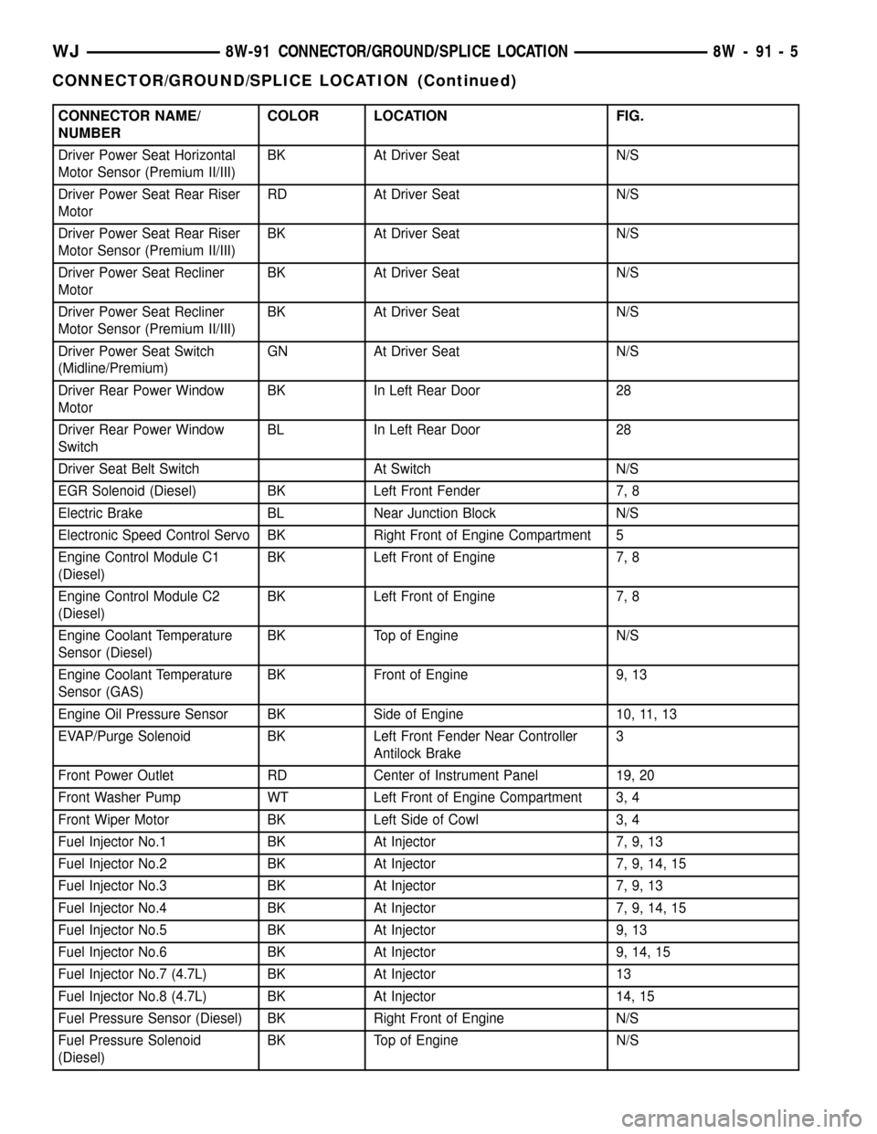
CONNECTOR NAME/
NUMBERCOLOR LOCATION FIG.
Driver Power Seat Horizontal
Motor Sensor (Premium II/III)BK At Driver Seat N/S
Driver Power Seat Rear Riser
MotorRD At Driver Seat N/S
Driver Power Seat Rear Riser
Motor Sensor (Premium II/III)BK At Driver Seat N/S
Driver Power Seat Recliner
MotorBK At Driver Seat N/S
Driver Power Seat Recliner
Motor Sensor (Premium II/III)BK At Driver Seat N/S
Driver Power Seat Switch
(Midline/Premium)GN At Driver Seat N/S
Driver Rear Power Window
MotorBK In Left Rear Door 28
Driver Rear Power Window
SwitchBL In Left Rear Door 28
Driver Seat Belt Switch At Switch N/S
EGR Solenoid (Diesel) BK Left Front Fender 7, 8
Electric Brake BL Near Junction Block N/S
Electronic Speed Control Servo BK Right Front of Engine Compartment 5
Engine Control Module C1
(Diesel)BK Left Front of Engine 7, 8
Engine Control Module C2
(Diesel)BK Left Front of Engine 7, 8
Engine Coolant Temperature
Sensor (Diesel)BK Top of Engine N/S
Engine Coolant Temperature
Sensor (GAS)BK Front of Engine 9, 13
Engine Oil Pressure Sensor BK Side of Engine 10, 11, 13
EVAP/Purge Solenoid BK Left Front Fender Near Controller
Antilock Brake3
Front Power Outlet RD Center of Instrument Panel 19, 20
Front Washer Pump WT Left Front of Engine Compartment 3, 4
Front Wiper Motor BK Left Side of Cowl 3, 4
Fuel Injector No.1 BK At Injector 7, 9, 13
Fuel Injector No.2 BK At Injector 7, 9, 14, 15
Fuel Injector No.3 BK At Injector 7, 9, 13
Fuel Injector No.4 BK At Injector 7, 9, 14, 15
Fuel Injector No.5 BK At Injector 9, 13
Fuel Injector No.6 BK At Injector 9, 14, 15
Fuel Injector No.7 (4.7L) BK At Injector 13
Fuel Injector No.8 (4.7L) BK At Injector 14, 15
Fuel Pressure Sensor (Diesel) BK Right Front of Engine N/S
Fuel Pressure Solenoid
(Diesel)BK Top of Engine N/S
WJ8W-91 CONNECTOR/GROUND/SPLICE LOCATION 8W - 91 - 5
CONNECTOR/GROUND/SPLICE LOCATION (Continued)
Page 1182 of 2199
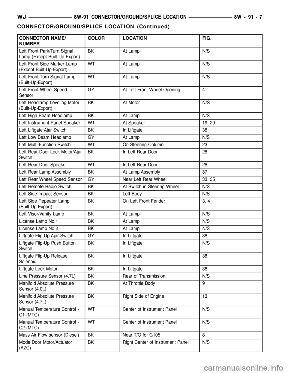
CONNECTOR NAME/
NUMBERCOLOR LOCATION FIG.
Left Front Park/Turn Signal
Lamp (Except Built-Up-Export)BK At Lamp N/S
Left Front Side Marker Lamp
(Except Built-Up-Export)WT At Lamp N/S
Left Front Turn Signal Lamp
(Built-Up-Export)WT At Lamp N/S
Left Front Wheel Speed
SensorGY At Left Front Wheel Opening 4
Left Headlamp Leveling Motor
(Built-Up-Export)BK At Motor N/S
Left High Beam Headlamp BK At Lamp N/S
Left Instrument Panel Speaker WT At Speaker 19, 20
Left Liftgate Ajar Switch BK In Liftgate 38
Left Low Beam Headlamp GY At Lamp N/S
Left Multi-Function Switch WT On Steering Column 23
Left Rear Door Lock Motor/Ajar
SwitchBK In Left Rear Door 28
Left Rear Door Speaker WT In Left Rear Door 28
Left Rear Lamp Assembly BK At Lamp Assembly 37
Left Rear Wheel Speed Sensor GY Near Left Rear Wheel 33, 35
Left Remote Radio Switch BK At Switch in Steering Wheel N/S
Left Side Impact Sensor BK Left Body N/S
Left Side Repeater Lamp
(Built-Up-Export)BK On Left Front Fender 3, 4
Left Visor/Vanity Lamp BK At Lamp N/S
License Lamp No.1 BK At Lamp N/S
License Lamp No.2 BK At Lamp N/S
Liftgate Flip-Up Ajar Switch GY In Liftgate 38
Liftgate Flip-Up Push Button
SwitchBK In Liftgate N/S
Liftgate Flip-Up Release
SolenoidBK In Liftgate 38
Liftgate Lock Motor BK In Liftgate 38
Line Pressure Sensor (4.7L) BK Rear of Transmission N/S
Manifold Absolute Pressure
Sensor (4.0L)BK At Throttle Body 9
Manifold Absolute Pressure
Sensor (4.7L)BK Right Side of Engine 13
Manual Temperature Control -
C1 (MTC)WT Center of Instrument Panel N/S
Manual Temperature Control -
C2 (MTC)WT Center of Instrument Panel N/S
Mass Air Flow sensor (Diesel) BK Near T/O for G105 8
Mode Door Motor/Actuator
(AZC)BK Right Center of Instrument Panel N/S
WJ8W-91 CONNECTOR/GROUND/SPLICE LOCATION 8W - 91 - 7
CONNECTOR/GROUND/SPLICE LOCATION (Continued)
Page 1187 of 2199
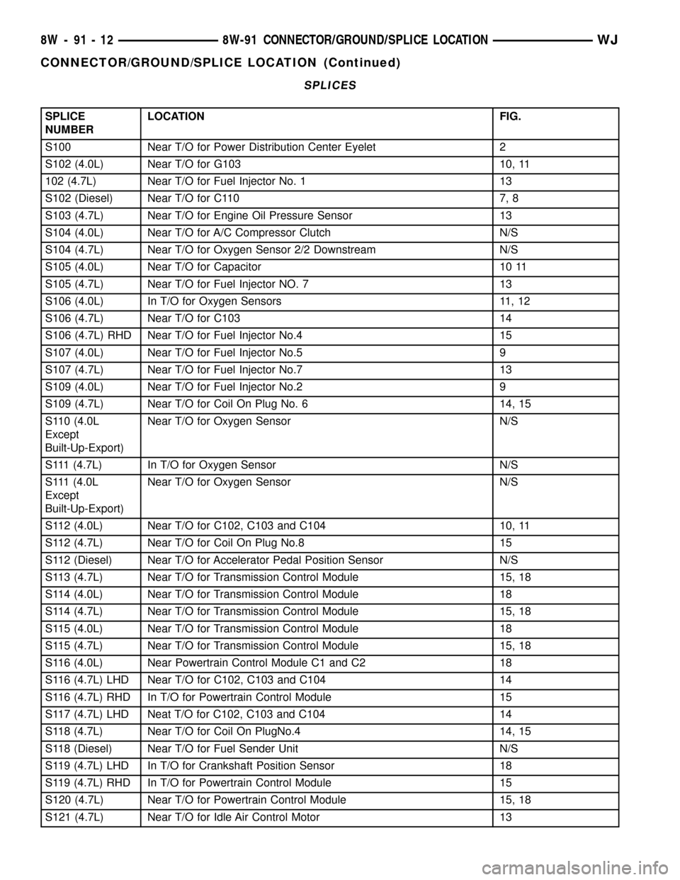
SPLICES
SPLICE
NUMBERLOCATION FIG.
S100 Near T/O for Power Distribution Center Eyelet 2
S102 (4.0L) Near T/O for G103 10, 11
102 (4.7L) Near T/O for Fuel Injector No. 1 13
S102 (Diesel) Near T/O for C110 7, 8
S103 (4.7L) Near T/O for Engine Oil Pressure Sensor 13
S104 (4.0L) Near T/O for A/C Compressor Clutch N/S
S104 (4.7L) Near T/O for Oxygen Sensor 2/2 Downstream N/S
S105 (4.0L) Near T/O for Capacitor 10 11
S105 (4.7L) Near T/O for Fuel Injector NO. 7 13
S106 (4.0L) In T/O for Oxygen Sensors 11, 12
S106 (4.7L) Near T/O for C103 14
S106 (4.7L) RHD Near T/O for Fuel Injector No.4 15
S107 (4.0L) Near T/O for Fuel Injector No.5 9
S107 (4.7L) Near T/O for Fuel Injector No.7 13
S109 (4.0L) Near T/O for Fuel Injector No.2 9
S109 (4.7L) Near T/O for Coil On Plug No. 6 14, 15
S110 (4.0L
Except
Built-Up-Export)Near T/O for Oxygen Sensor N/S
S111 (4.7L) In T/O for Oxygen Sensor N/S
S111 (4.0L
Except
Built-Up-Export)Near T/O for Oxygen Sensor N/S
S112 (4.0L) Near T/O for C102, C103 and C104 10, 11
S112 (4.7L) Near T/O for Coil On Plug No.8 15
S112 (Diesel) Near T/O for Accelerator Pedal Position Sensor N/S
S113 (4.7L) Near T/O for Transmission Control Module 15, 18
S114 (4.0L) Near T/O for Transmission Control Module 18
S114 (4.7L) Near T/O for Transmission Control Module 15, 18
S115 (4.0L) Near T/O for Transmission Control Module 18
S115 (4.7L) Near T/O for Transmission Control Module 15, 18
S116 (4.0L) Near Powertrain Control Module C1 and C2 18
S116 (4.7L) LHD Near T/O for C102, C103 and C104 14
S116 (4.7L) RHD In T/O for Powertrain Control Module 15
S117 (4.7L) LHD Neat T/O for C102, C103 and C104 14
S118 (4.7L) Near T/O for Coil On PlugNo.4 14, 15
S118 (Diesel) Near T/O for Fuel Sender Unit N/S
S119 (4.7L) LHD In T/O for Crankshaft Position Sensor 18
S119 (4.7L) RHD In T/O for Powertrain Control Module 15
S120 (4.7L) Near T/O for Powertrain Control Module 15, 18
S121 (4.7L) Near T/O for Idle Air Control Motor 13
8W - 91 - 12 8W-91 CONNECTOR/GROUND/SPLICE LOCATIONWJ
CONNECTOR/GROUND/SPLICE LOCATION (Continued)
Page 1244 of 2199
ENGINE
TABLE OF CONTENTS
page page
ENGINE - 4.0L............................ 1ENGINE - 4.7L........................... 61
ENGINE - 4.0L
TABLE OF CONTENTS
page page
ENGINE - 4.0L
DESCRIPTION..........................2
DIAGNOSIS AND TESTING
DIAGNOSIS AND TESTING - ENGINE
DIAGNOSIS - INTRODUCTION............3
DIAGNOSIS AND TESTING - ENGINE
DIAGNOSIS - PERFORMANCE............4
DIAGNOSIS AND TESTINGÐ ENGINE
DIAGNOSIS - MECHANICAL..............6
DIAGNOSIS AND TESTINGÐCYLINDER
COMPRESSION PRESSURE..............8
DIAGNOSIS AND TESTING - CYLINDER
COMBUSTION PRESSURE LEAKAGE.......8
DIAGNOSIS AND TESTINGÐREAR SEAL
AREA LEAKS..........................9
STANDARD PROCEDURE
STANDARD PROCEDURE - FORM-IN-
PLACE GASKETS AND SEALERS..........9
STANDARD PROCEDURE - REPAIR
DAMAGED OR WORN THREADS.........10
STANDARD PROCEDUREÐHYDROSTATIC
LOCK...............................10
STANDARD PROCEDURE - CYLINDER
BORE HONING.......................10
STANDARD PROCEDURE - ENGINE CORE
AND OIL GALLERY PLUGS..............11
REMOVAL.............................11
INSTALLATION.........................13
SPECIFICATIONS
ENGINE - 4.0L........................14
TORQUE - 4.0L ENGINE................17
AIR CLEANER ELEMENT
REMOVAL - 4.0L........................18
INSTALLATION - 4.0L....................19
AIR CLEANER HOUSING
REMOVAL - 4.0L........................19
INSTALLATION - 4.0L....................19CYLINDER HEAD
DESCRIPTION.........................19
REMOVAL.............................19
CLEANING............................21
INSPECTION..........................21
INSTALLATION.........................21
CYLINDER HEAD COVER(S)
DESCRIPTION.........................22
REMOVAL.............................22
CLEANING............................23
INSPECTION..........................23
INSTALLATION.........................23
INTAKE/EXHAUST VALVES & SEATS
DESCRIPTION.........................23
STANDARD PROCEDURE - VALVE SERVICE . . 23
REMOVAL.............................25
INSTALLATION.........................25
ROCKER ARM / ADJUSTER ASSEMBLY
DESCRIPTION.........................26
OPERATION...........................26
REMOVAL.............................26
CLEANING............................26
INSPECTION..........................27
INSTALLATION.........................27
VALVE STEM SEALS
DESCRIPTION.........................27
VALVE SPRINGS
DESCRIPTION.........................28
STANDARD PROCEDURE - VALVE SPRING
TENSION TEST.......................28
REMOVAL.............................28
INSTALLATION.........................29
ENGINE BLOCK
CLEANING............................30
INSPECTION..........................30
CAMSHAFT & BEARINGS
DESCRIPTION.........................30
WJENGINE 9 - 1
Page 1245 of 2199
REMOVAL
REMOVAL - CAMSHAFT BEARINGS.......31
REMOVAL - CAMSHAFT................31
INSPECTION
INSPECTION - CAMSHAFT BEARINGS.....31
INSPECTION - CAMSHAFT..............31
INSTALLATION
INSTALLATION - CAMSHAFT BEARINGS . . . 32
INSTALLATION - CAMSHAFT............32
CONNECTING ROD BEARINGS
STANDARD PROCEDURE - FITTING
CONNECTING ROD BEARINGS..........33
CRANKSHAFT
DESCRIPTION.........................35
CRANKSHAFT MAIN BEARINGS
STANDARD PROCEDURE - FITTING
CRANKSHAFT MAIN BEARINGS..........36
REMOVAL.............................39
INSPECTION..........................40
INSTALLATION.........................40
CRANKSHAFT OIL SEAL - FRONT
REMOVAL.............................41
INSTALLATION.........................41
CRANKSHAFT OIL SEAL - REAR
REMOVAL.............................42
INSTALLATION.........................42
HYDRAULIC LIFTERS
DESCRIPTION.........................43
REMOVAL.............................43
CLEANING............................43
INSPECTION..........................43
INSTALLATION.........................43
PISTON & CONNECTING ROD
DESCRIPTION.........................44
STANDARD PROCEDURE - PISTON FITTING . 44
REMOVAL.............................45
INSTALLATION.........................46
PISTON RINGS
STANDARD PROCEDURE - PISTON RING
FITTING.............................47
VIBRATION DAMPER
REMOVAL.............................49
INSTALLATION.........................49STRUCTURAL SUPPORT
REMOVAL.............................49
INSTALLATION.........................50
LUBRICATION
DESCRIPTION.........................50
OPERATION...........................50
DIAGNOSIS AND TESTING
DIAGNOSIS AND TESTING - ENGINE OIL
PRESSURE..........................51
DIAGNOSIS AND TESTING - ENGINE OIL
LEAK...............................51
OIL
STANDARD PROCEDURE - ENGINE OIL
SERVICE............................53
OIL FILTER
REMOVAL.............................53
INSTALLATION.........................54
OIL PAN
DESCRIPTION.........................54
REMOVAL.............................54
INSTALLATION.........................55
ENGINE OIL PRESSURE SENSOR
DESCRIPTION.........................56
OPERATION...........................56
OIL PUMP
REMOVAL.............................56
INSTALLATION.........................57
INTAKE MANIFOLD
DESCRIPTION.........................57
DIAGNOSIS AND TESTING - INTAKE
MANIFOLD LEAKAGE..................57
REMOVAL.............................57
INSTALLATION.........................57
EXHAUST MANIFOLD
DESCRIPTION.........................58
REMOVAL.............................58
INSTALLATION.........................58
TIMING BELT / CHAIN COVER(S)
REMOVAL.............................58
INSTALLATION.........................58
TIMING BELT/CHAIN AND SPROCKETS
REMOVAL.............................60
INSTALLATION.........................60
ENGINE - 4.0L
DESCRIPTION
The 4.0 Liter (242 CID) six-cylinder engine is an
In-line, lightweight, overhead valve engine. This
engine is designed for unleaded fuel.
The engine cylinder head has dual quench-type
combustion chambers that create turbulence and fast
burning of the air/fuel mixture. This results in better
fuel economy.
The cylinders are numbered 1 through 6 from front
to rear. The firing order is 1-5-3-6-2-4 (Fig. 1).The crankshaft rotation is clockwise, when viewed
from the front of the engine. The crankshaft rotates
within seven main bearings. The camshaft rotates
within four bearings.
The engine Build Date Code is located on a
machined surface on the right side of the cylinder
block between the No.2 and No.3 cylinders (Fig. 2).
The digits of the code identify:
²1st DigitÐThe year (8 = 1998).
²2nd & 3rd DigitsÐThe month (01 - 12).
²4th & 5th DigitsÐThe engine type/fuel system/
compression ratio (MX = A 4.0 Liter (242 CID) 8.7:1
compression ratio engine with a multi-point fuel
injection system).
9 - 2 ENGINE - 4.0LWJ
Page 1246 of 2199
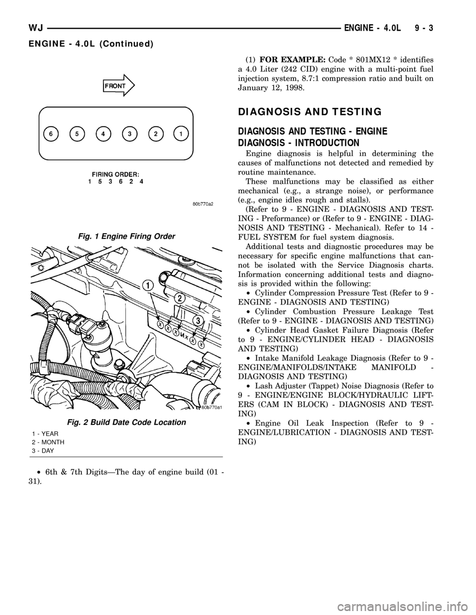
²6th & 7th DigitsÐThe day of engine build (01 -
31).(1)FOR EXAMPLE:Code * 801MX12 * identifies
a 4.0 Liter (242 CID) engine with a multi-point fuel
injection system, 8.7:1 compression ratio and built on
January 12, 1998.
DIAGNOSIS AND TESTING
DIAGNOSIS AND TESTING - ENGINE
DIAGNOSIS - INTRODUCTION
Engine diagnosis is helpful in determining the
causes of malfunctions not detected and remedied by
routine maintenance.
These malfunctions may be classified as either
mechanical (e.g., a strange noise), or performance
(e.g., engine idles rough and stalls).
(Refer to 9 - ENGINE - DIAGNOSIS AND TEST-
ING - Preformance) or (Refer to 9 - ENGINE - DIAG-
NOSIS AND TESTING - Mechanical). Refer to 14 -
FUEL SYSTEM for fuel system diagnosis.
Additional tests and diagnostic procedures may be
necessary for specific engine malfunctions that can-
not be isolated with the Service Diagnosis charts.
Information concerning additional tests and diagno-
sis is provided within the following:
²Cylinder Compression Pressure Test (Refer to 9 -
ENGINE - DIAGNOSIS AND TESTING)
²Cylinder Combustion Pressure Leakage Test
(Refer to 9 - ENGINE - DIAGNOSIS AND TESTING)
²Cylinder Head Gasket Failure Diagnosis (Refer
to 9 - ENGINE/CYLINDER HEAD - DIAGNOSIS
AND TESTING)
²Intake Manifold Leakage Diagnosis (Refer to 9 -
ENGINE/MANIFOLDS/INTAKE MANIFOLD -
DIAGNOSIS AND TESTING)
²Lash Adjuster (Tappet) Noise Diagnosis (Refer to
9 - ENGINE/ENGINE BLOCK/HYDRAULIC LIFT-
ERS (CAM IN BLOCK) - DIAGNOSIS AND TEST-
ING)
²Engine Oil Leak Inspection (Refer to 9 -
ENGINE/LUBRICATION - DIAGNOSIS AND TEST-
ING)
Fig. 1 Engine Firing Order
Fig. 2 Build Date Code Location
1 - YEAR
2 - MONTH
3-DAY
WJENGINE - 4.0L 9 - 3
ENGINE - 4.0L (Continued)
Page 1247 of 2199
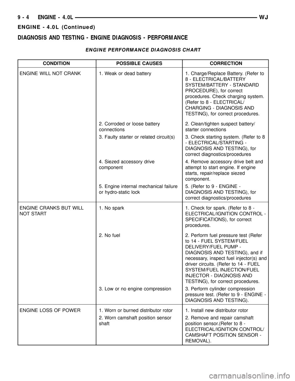
DIAGNOSIS AND TESTING - ENGINE DIAGNOSIS - PERFORMANCE
ENGINE PERFORMANCE DIAGNOSIS CHART
CONDITION POSSIBLE CAUSES CORRECTION
ENGINE WILL NOT CRANK 1. Weak or dead battery 1. Charge/Replace Battery. (Refer to
8 - ELECTRICAL/BATTERY
SYSTEM/BATTERY - STANDARD
PROCEDURE), for correct
procedures. Check charging system.
(Refer to 8 - ELECTRICAL/
CHARGING - DIAGNOSIS AND
TESTING), for correct procedures.
2. Corroded or loose battery
connections2. Clean/tighten suspect battery/
starter connections
3. Faulty starter or related circuit(s) 3. Check starting system. (Refer to 8
- ELECTRICAL/STARTING -
DIAGNOSIS AND TESTING), for
correct diagnostics/procedures
4. Siezed accessory drive
component4. Remove accessory drive belt and
attempt to start engine. If engine
starts, repair/replace siezed
component.
5. Engine internal mechanical failure
or hydro-static lock5. (Refer to 9 - ENGINE -
DIAGNOSIS AND TESTING), for
correct diagnostics/procedures
ENGINE CRANKS BUT WILL
NOT START1. No spark 1. Check for spark. (Refer to 8 -
ELECTRICAL/IGNITION CONTROL -
SPECIFICATIONS), for correct
procedures.
2. No fuel 2. Perform fuel pressure test (Refer
to 14 - FUEL SYSTEM/FUEL
DELIVERY/FUEL PUMP -
DIAGNOSIS AND TESTING), and if
necessary, inspect fuel injector(s) and
driver circuits. (Refer to 14 - FUEL
SYSTEM/FUEL INJECTION/FUEL
INJECTOR - DIAGNOSIS AND
TESTING), for correct procedures.
3. Low or no engine compression 3. Perform cylinder compression
pressure test. (Refer to 9 - ENGINE -
DIAGNOSIS AND TESTING).
ENGINE LOSS OF POWER 1. Worn or burned distributor rotor 1. Install new distributor rotor
2. Worn camshaft position sensor
shaft2. Remove and repair camshaft
position sensor.(Refer to 8 -
ELECTRICAL/IGNITION CONTROL/
CAMSHAFT POSITION SENSOR -
REMOVAL).
9 - 4 ENGINE - 4.0LWJ
ENGINE - 4.0L (Continued)
Page 1249 of 2199
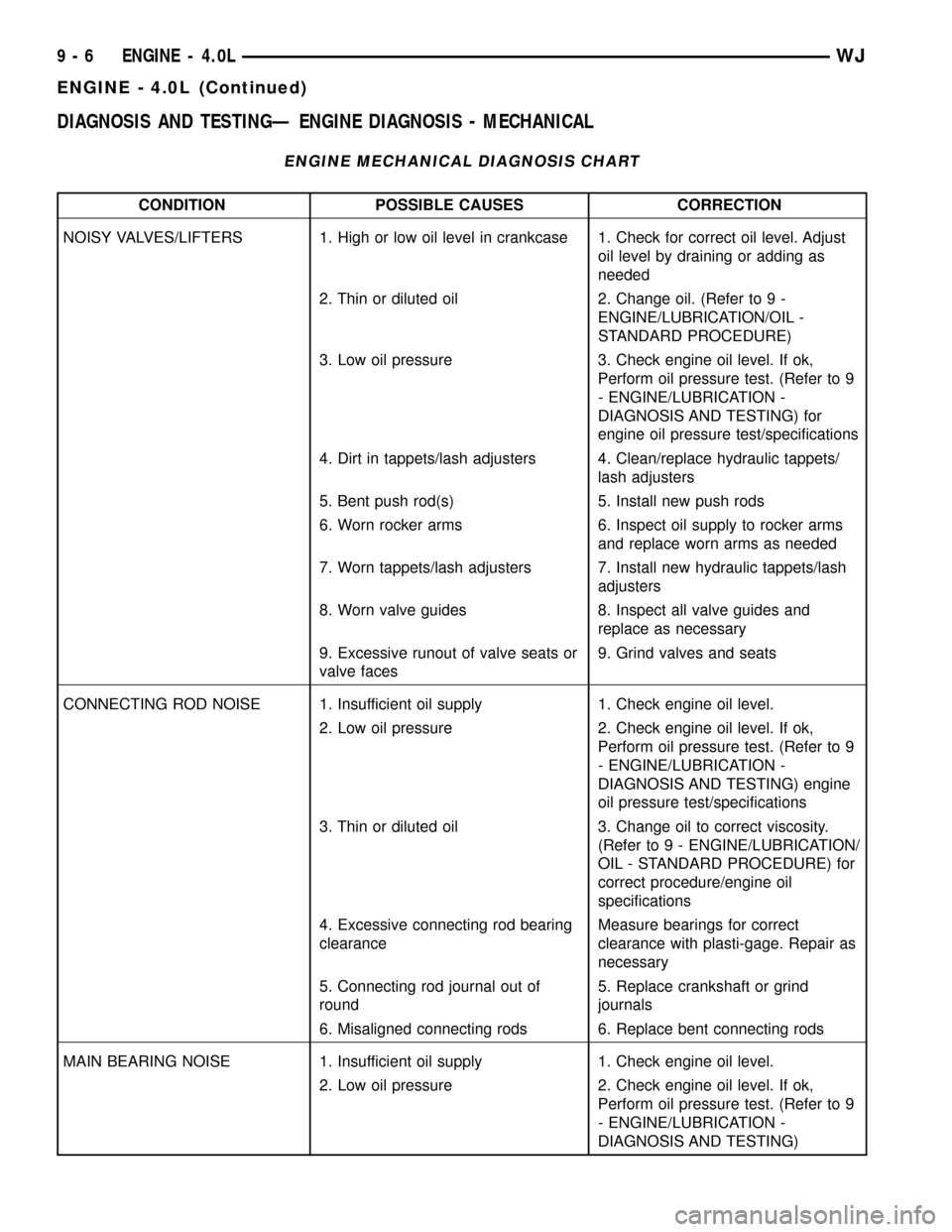
DIAGNOSIS AND TESTINGÐ ENGINE DIAGNOSIS - MECHANICAL
ENGINE MECHANICAL DIAGNOSIS CHART
CONDITION POSSIBLE CAUSES CORRECTION
NOISY VALVES/LIFTERS 1. High or low oil level in crankcase 1. Check for correct oil level. Adjust
oil level by draining or adding as
needed
2. Thin or diluted oil 2. Change oil. (Refer to 9 -
ENGINE/LUBRICATION/OIL -
STANDARD PROCEDURE)
3. Low oil pressure 3. Check engine oil level. If ok,
Perform oil pressure test. (Refer to 9
- ENGINE/LUBRICATION -
DIAGNOSIS AND TESTING) for
engine oil pressure test/specifications
4. Dirt in tappets/lash adjusters 4. Clean/replace hydraulic tappets/
lash adjusters
5. Bent push rod(s) 5. Install new push rods
6. Worn rocker arms 6. Inspect oil supply to rocker arms
and replace worn arms as needed
7. Worn tappets/lash adjusters 7. Install new hydraulic tappets/lash
adjusters
8. Worn valve guides 8. Inspect all valve guides and
replace as necessary
9. Excessive runout of valve seats or
valve faces9. Grind valves and seats
CONNECTING ROD NOISE 1. Insufficient oil supply 1. Check engine oil level.
2. Low oil pressure 2. Check engine oil level. If ok,
Perform oil pressure test. (Refer to 9
- ENGINE/LUBRICATION -
DIAGNOSIS AND TESTING) engine
oil pressure test/specifications
3. Thin or diluted oil 3. Change oil to correct viscosity.
(Refer to 9 - ENGINE/LUBRICATION/
OIL - STANDARD PROCEDURE) for
correct procedure/engine oil
specifications
4. Excessive connecting rod bearing
clearanceMeasure bearings for correct
clearance with plasti-gage. Repair as
necessary
5. Connecting rod journal out of
round5. Replace crankshaft or grind
journals
6. Misaligned connecting rods 6. Replace bent connecting rods
MAIN BEARING NOISE 1. Insufficient oil supply 1. Check engine oil level.
2. Low oil pressure 2. Check engine oil level. If ok,
Perform oil pressure test. (Refer to 9
- ENGINE/LUBRICATION -
DIAGNOSIS AND TESTING)
9 - 6 ENGINE - 4.0LWJ
ENGINE - 4.0L (Continued)
Page 1250 of 2199
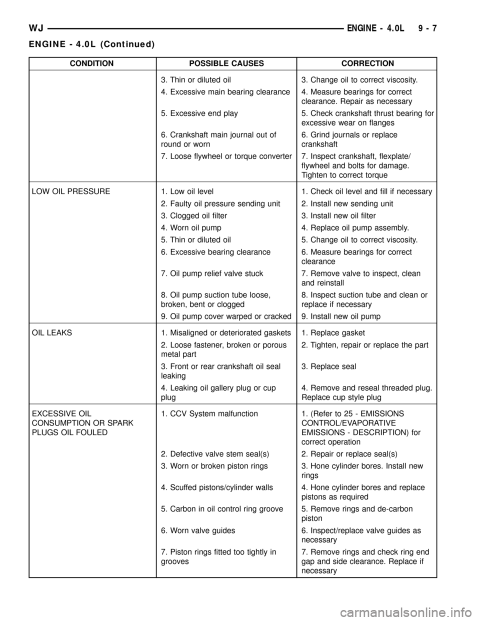
CONDITION POSSIBLE CAUSES CORRECTION
3. Thin or diluted oil 3. Change oil to correct viscosity.
4. Excessive main bearing clearance 4. Measure bearings for correct
clearance. Repair as necessary
5. Excessive end play 5. Check crankshaft thrust bearing for
excessive wear on flanges
6. Crankshaft main journal out of
round or worn6. Grind journals or replace
crankshaft
7. Loose flywheel or torque converter 7. Inspect crankshaft, flexplate/
flywheel and bolts for damage.
Tighten to correct torque
LOW OIL PRESSURE 1. Low oil level 1. Check oil level and fill if necessary
2. Faulty oil pressure sending unit 2. Install new sending unit
3. Clogged oil filter 3. Install new oil filter
4. Worn oil pump 4. Replace oil pump assembly.
5. Thin or diluted oil 5. Change oil to correct viscosity.
6. Excessive bearing clearance 6. Measure bearings for correct
clearance
7. Oil pump relief valve stuck 7. Remove valve to inspect, clean
and reinstall
8. Oil pump suction tube loose,
broken, bent or clogged8. Inspect suction tube and clean or
replace if necessary
9. Oil pump cover warped or cracked 9. Install new oil pump
OIL LEAKS 1. Misaligned or deteriorated gaskets 1. Replace gasket
2. Loose fastener, broken or porous
metal part2. Tighten, repair or replace the part
3. Front or rear crankshaft oil seal
leaking3. Replace seal
4. Leaking oil gallery plug or cup
plug4. Remove and reseal threaded plug.
Replace cup style plug
EXCESSIVE OIL
CONSUMPTION OR SPARK
PLUGS OIL FOULED1. CCV System malfunction 1. (Refer to 25 - EMISSIONS
CONTROL/EVAPORATIVE
EMISSIONS - DESCRIPTION) for
correct operation
2. Defective valve stem seal(s) 2. Repair or replace seal(s)
3. Worn or broken piston rings 3. Hone cylinder bores. Install new
rings
4. Scuffed pistons/cylinder walls 4. Hone cylinder bores and replace
pistons as required
5. Carbon in oil control ring groove 5. Remove rings and de-carbon
piston
6. Worn valve guides 6. Inspect/replace valve guides as
necessary
7. Piston rings fitted too tightly in
grooves7. Remove rings and check ring end
gap and side clearance. Replace if
necessary
WJENGINE - 4.0L 9 - 7
ENGINE - 4.0L (Continued)