warning signal JEEP GRAND CHEROKEE 2023 User Guide
[x] Cancel search | Manufacturer: JEEP, Model Year: 2023, Model line: GRAND CHEROKEE, Model: JEEP GRAND CHEROKEE 2023Pages: 424, PDF Size: 15.48 MB
Page 116 of 424
114GETTING TO KNOW YOUR INSTRUMENT PANEL
also reduces fuel efficiency and tire tread life, and
may affect the vehicle’s handling and stopping
ability.
Please note that the TPMS is not a substitute for
proper tire maintenance, and it is the driver’s
responsibility to maintain correct tire pressure,
even if underinflation has not reached the level to
trigger illumination of the TPMS low tire pressure
telltale.
Your vehicle has also been equipped with a TPMS
malfunction indicator to indicate when the system
is not operating properly. The TPMS malfunction
indicator is combined with the low tire pressure
telltale. When the system detects a malfunction,
the telltale will flash for approximately one minute
and then remain continuously illuminated. This
sequence will continue upon subsequent vehicle
start-ups as long as the malfunction exists. When
the malfunction indicator is illuminated, the
system may not be able to detect or signal low tire
pressure as intended. TPMS malfunctions may
occur for a variety of reasons, including the
installation of replacement or alternate tires or
wheels on the vehicle that prevent the TPMS from
functioning properly. Always check the TPMS
malfunction telltale after replacing one or more
tires or wheels on your vehicle to ensure that the
replacement or alternate tires and wheels allow
the TPMS to continue to function properly.
YELLOW INDICATOR LIGHTS
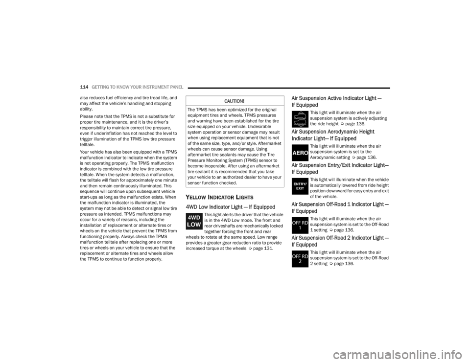
4WD Low Indicator Light — If Equipped
This light alerts the driver that the vehicle
is in the 4WD Low mode. The front and
rear driveshafts are mechanically locked
together forcing the front and rear
wheels to rotate at the same speed. Low range
provides a greater gear reduction ratio to provide
increased torque at the wheels Ú page 131.
Air Suspension Active Indicator Light —
If Equipped
This light will illuminate when the air
suspension system is actively adjusting
the ride height Úpage 136.
Air Suspension Aerodynamic Height
Indicator Light— If Equipped
This light will illuminate when the air
suspension system is set to the
Aerodynamic setting Ú page 136.
Air Suspension Entry/Exit Indicator Light—
If Equipped
This light will illuminate when the vehicle
is automatically lowered from ride height
position downward for easy entry and exit
of the vehicle.
Air Suspension Off-Road 1 Indicator Light —
If Equipped
This light will illuminate when the air
suspension system is set to the Off-Road
1 setting Úpage 136.
Air Suspension Off-Road 2 Indicator Light —
If Equipped
This light will illuminate when the air
suspension system is set to the Off-Road
2 setting Úpage 136.
CAUTION!
The TPMS has been optimized for the original
equipment tires and wheels. TPMS pressures
and warning have been established for the tire
size equipped on your vehicle. Undesirable
system operation or sensor damage may result
when using replacement equipment that is not
of the same size, type, and/or style. Aftermarket
wheels can cause sensor damage. Using
aftermarket tire sealants may cause the Tire
Pressure Monitoring System (TPMS) sensor to
become inoperable. After using an aftermarket
tire sealant it is recommended that you take
your vehicle to an authorized dealer to have your
sensor function checked.
23_WL_OM_EN_USC_t.book Page 114
Page 118 of 424
116GETTING TO KNOW YOUR INSTRUMENT PANEL
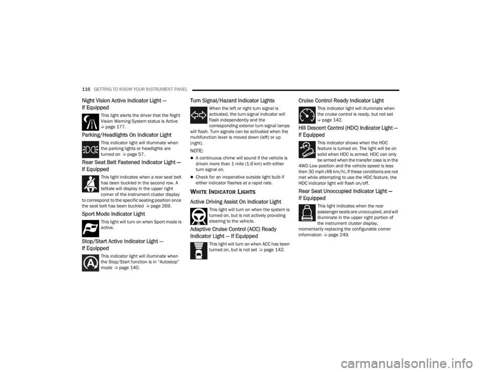
Night Vision Active Indicator Light —
If Equipped
This light alerts the driver that the Night
Vision Warning System status is Active
Úpage 177.
Parking/Headlights On Indicator Light
This indicator light will illuminate when
the parking lights or headlights are
turned on Ú page 57.
Rear Seat Belt Fastened Indicator Light —
If Equipped
This light indicates when a rear seat belt
has been buckled in the second row. A
telltale will display in the upper right
corner of the instrument cluster display
to correspond to the specific seating position once
the seat belt has been buckled Ú page 269.
Sport Mode Indicator Light
This light will turn on when Sport mode is
active.
Stop/Start Active Indicator Light —
If Equipped
This indicator light will illuminate when
the Stop/Start function is in “Autostop”
mode Úpage 140.
Turn Signal/Hazard Indicator Lights
When the left or right turn signal is
activated, the turn signal indicator will
flash independently and the
corresponding exterior turn signal lamps
will flash. Turn signals can be activated when the
multifunction lever is moved down (left) or up
(right).
NOTE:
A continuous chime will sound if the vehicle is
driven more than 1 mile (1.6 km) with either
turn signal on.
Check for an inoperative outside light bulb if
either indicator flashes at a rapid rate.
WHITE INDICATOR LIGHTS
Active Driving Assist On Indicator Light
This light will turn on when the system is
turned on, but is not actively providing
steering to the vehicle.
Adaptive Cruise Control (ACC) Ready
Indicator Light — If Equipped
This light will turn on when ACC has been
turned on, but is not set Ú page 142.
Cruise Control Ready Indicator Light
This indicator light will illuminate when
the cruise control is ready, but not set
Úpage 142.
Hill Descent Control (HDC) Indicator Light —
If Equipped
This indicator shows when the HDC
feature is turned on. The light will be on
solid when HDC is armed. HDC can only
be armed when the transfer case is in the
4WD Low position and the vehicle speed is less
then 30 mph (48 km/h). If these conditions are not
met while attempting to use the HDC feature, the
HDC indicator light will flash on/off.
Rear Seat Unoccupied Indicator Light —
If Equipped
This light indicates when the rear
passenger seats are unoccupied, and will
illuminate in the upper right portion of
the instrument cluster display,
momentarily replacing the configurable corner
information Ú page 249.
23_WL_OM_EN_USC_t.book Page 116
Page 149 of 424
STARTING AND OPERATING147
To decrease the distance setting, push the
Distance Decrease button and release. Each time
the button is pushed, the distance setting
decreases by one bar (shorter).
If there is no vehicle ahead, the vehicle will
maintain the set speed. If a slower moving vehicle
is detected in the same lane, the instrument
cluster display will show the ACC Set With Target
Detected Indicator Light, and the system will adjust
the vehicle speed automatically to maintain the
distance setting, regardless of the set speed.
The vehicle will then maintain the set distance
until:
The vehicle ahead accelerates to a speed above
the set speed.
The vehicle ahead moves out of your lane or
view of the sensor.
The distance setting is changed.
The system disengages Ú page 144.
The maximum braking applied by ACC is limited;
however, the driver can always apply the brakes
manually, if necessary.
NOTE:The brake lights will illuminate whenever the ACC
system applies the brakes. A Proximity Warning will alert the driver if ACC
predicts that its maximum braking level is not
sufficient to maintain the set distance. If this
occurs, a visual alert “BRAKE!” will flash in the
instrument cluster display and a chime will sound
while ACC continues to apply its maximum braking
capacity.
NOTE:The “BRAKE!” screen in the instrument cluster
display is a warning for the driver to take action
and does not necessarily mean that the Forward
Collision Warning system is applying the brakes
autonomously.
Overtake Aid
When driving with Adaptive Cruise Control (ACC)
engaged and following a vehicle, the system will
provide an additional acceleration up to the ACC
set speed to assist in passing the vehicle. This
additional acceleration is triggered when the driver
utilizes the left turn signal and will only be active
when passing on the left hand side.
ACC Operation At Stop
If the ACC system brings your vehicle to a standstill
while following a vehicle ahead, your vehicle will
resume motion, without any driver interaction, if
the vehicle ahead starts moving within two
seconds of your vehicle coming to a standstill.If the vehicle in front does not start moving within
two seconds of your vehicle coming to a standstill,
the driver will either have to push the RES (resume)
button, or apply the accelerator pedal to reengage
the ACC to the existing set speed.
NOTE:
If your vehicle is at a standstill for longer than
two seconds, the system will hold brake pres
-
sure for up to 10 minutes. If no driver action is
taken after the 10 minutes, the Electric Park
Brake will be applied and the ACC system will
cancel.
While ACC is holding your vehicle at a standstill
(or the vehicle is traveling below 3 mph
(5 km/h), and the driver seat belt is unbuckled
or the driver door is opened, the Electric Park
Brake will be applied and the ACC system will
cancel.
WARNING!
When the ACC system is resumed, the driver
must ensure that there are no pedestrians,
vehicles or objects in the path of the vehicle.
Failure to follow these warnings can result in a
collision and death or serious personal injury.
4
23_WL_OM_EN_USC_t.book Page 147
Page 155 of 424
STARTING AND OPERATING153
The driver can override ADA at any time by
braking, accelerating, or steering the vehicle.
Just like ACC, ADA will maintain a set speed as long
as the set distance between your vehicle and the
vehicle in front is maintained. ADA will also keep
your vehicle centered between the lane lines, and
monitor for other vehicles in adjacent lanes by
utilizing the Blind Spot Monitoring sensors.
Two types of Active Driving Assist systems are
available:
Base ADA system
Hands-Free ADA system
Base Active Driving Assist System — If Equipped
The Base ADA system uses sensors within the
steering wheel to measure driver attentiveness,
and requires that the driver have their hands on
the steering wheel at all times.
The system will generally aim to keep the vehicle
centered in the lane, but when the driver turns the
steering wheel (e.g. to move farther away from a
large vehicle in an adjacent lane) the system will
reduce its control and enter "co-steering" mode.
While in co-steering mode, the system will provide
reduced assistance and allow the driver to control
the path of the vehicle. Once the driver stops
providing input to the steering wheel, the system
will require a few seconds to fully resume lane
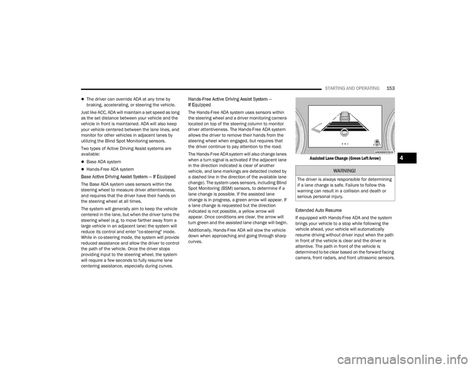
centering assistance, especially during curves. Hands-Free Active Driving Assist System —
If Equipped
The Hands-Free ADA system uses sensors within
the steering wheel and a driver monitoring camera
located on top of the steering column to monitor
driver attentiveness. The Hands-Free ADA system
allows the driver to remove their hands from the
steering wheel when engaged, but requires that
the driver continue to pay attention to the road.
The Hands-Free ADA system will also change lanes
when a turn signal is activated if the adjacent lane
in the direction indicated is clear of another
vehicle, and lane markings are detected (noted by
a dashed line in the direction of the available lane
change). The system uses sensors, including Blind
Spot Monitoring (BSM) sensors, to determine if a
lane change is possible. If the assisted lane
change is in progress, a green arrow will appear. If
a lane change is requested but the direction
indicated is not possible, a yellow arrow will
appear. Once conditions are clear, the arrow will
turn green and the assisted lane change will begin.
Additionally, Hands-Free ADA will slow the vehicle
down when approaching and going through sharp
curves.
Assisted Lane Change (Green Left Arrow)
Extended Auto Resume
If equipped with Hands-Free ADA and the system
brings your vehicle to a stop while following the
vehicle ahead, your vehicle will automatically
resume driving without driver input when the path
in front of the vehicle is clear and the driver is
attentive. The path in front of the vehicle is
determined to be clear based on the forward facing
camera, front radars, and front ultrasonic sensors.WARNING!
The driver is always responsible for determining
if a lane change is safe. Failure to follow this
warning can result in a collision and death or
serious personal injury.
4
23_WL_OM_EN_USC_t.book Page 153
Page 158 of 424
156STARTING AND OPERATING
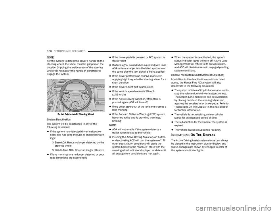
NOTE:For the system to detect the driver’s hands on the
steering wheel, the wheel must be gripped on the
outside. Gripping the inside areas of the steering
wheel will not satisfy the hands-on condition to
engage the system.
Do Not Grip Inside Of Steering Wheel
System Deactivation
The system will be deactivated in any of the
following situations:
If the system has detected driver inattentive -
ness, and has gone through all escalation warn -
ings:
Base ADA: Hands no longer detected on the
steering wheel
Hands-Free ADA: Driver no longer attentive
If lane markings are no longer detected or poor
road conditions are experienced
If the brake pedal is pressed or ACC system is
deactivated
If a turn signal is used when equipped with Base
ADA (unless a target is in the blind spot zone on
the same side the turn signal is being applied)
If the driver performs an evasive maneuver,
applying high torque to the steering wheel for a
short duration
If the driver’s seat belt is unbuckled
If the vehicle speed exceeds 90 mph
(145 km/h)
If the Active Driving Assist on/off button is
pushed again (ADA will turn off)
If the driver steers out of the lane and crosses a
lane marking
If the Forward Collision Warning (FCW) system
becomes active and is providing warnings/
braking
NOTE:
ADA will not enable if the system detects a
trailer is connected to the vehicle.
Pushing the Active Driving Assist on/off button
or deactivating ACC will turn the system off. All
other deactivation conditions will place the
system back into the “enabled” state with the
steering wheel indicator displayed in white until
all engagement conditions are met again.
When the system is deactivated, the system
status indicator lights will turn off, Active Lane
Management will return to its previous state,
and ACC will disable or remain engaged pending
system conditions.
Hands-Free System Deactivation (If Equipped)
In addition to the deactivation conditions listed
above, the Hands-Free ADA system will also
deactivate in the following situations:
The system initiates a Stop-In-Lane maneuver to
stop the vehicle due to driver inattentiveness.
The Stop-In-Lane maneuver can be overridden
by placing hands on the steering wheel and
applying the accelerator or brake pedal. Refer to
“Indications On The Display” in the next section
for further information.
The vehicle is not receiving a clear cellular
signal for an extended period of time.
The subscription for the Hands-Free system is
expired.
The vehicle leaves a supported roadway.
INDICATIONS ON THE DISPLAY
The Active Driving Assist system status can always
be viewed in the instrument cluster display, and
status changes are shown by changes in color of
the system’s indicator lights.
23_WL_OM_EN_USC_t.book Page 156
Page 167 of 424
STARTING AND OPERATING165
SIDE DISTANCE WARNING SYSTEM
The Side Distance Warning system detects the
presence of side obstacles near the vehicle using
the parking sensors located in the front and rear
fascia/bumpers.
Side Distance Warning Display
The Side Distance Warning screen will only be
displayed if this feature is enabled within Uconnect
Settings Úpage 204.
The system warns the driver with an acoustic
signal and, when enabled, with visual indications
on the instrument cluster display. When the vehicle is in DRIVE, the Side Distance
Warning volume/chime will match the Front
ParkSense volume and chime type.
When the vehicle is in REVERSE, the Side Distance
Warning volume/chime will match the Rear
ParkSense volume and chime type.NOTE:ParkSense will reduce the volume of the radio if on
when the system is sounding an audible tone. An
audible tone will only sound if a collision is
possible.
Activation/Deactivation
The system can operate only after driving a short
distance and if the vehicle speed is between 0 and
7 mph (0 and 11 km/h). The system can be
activated/deactivated via the Settings menu of the
Uconnect system. If the ParkSense System is
deactivated via the ParkSense hard switch, then
the Side Distance Warning system will
automatically be deactivated.
Message on the display for Side Distance Warning
feature:
“Wipe Sensors” — This message is displayed in the
case of a failure of the Side Distance Warning
system sensors. Free the bumpers of any
obstacles, ensure that the front and rear fascia/
bumper are free of snow, ice, mud, dirt and debris
to keep the ParkSense system operating properly.
“System Not Available” — This message is
displayed if the Side Distance Warning system is
not available. The failed operation of the system
might be due to the insufficient voltage from the
battery or other failures on the electrical system.
Contact an authorized dealer as soon as possible
to have the electrical system checked.CAUTION!
ParkSense is only a parking aid and it is
unable to recognize every obstacle, including
small obstacles. Parking curbs might be
temporarily detected or not detected at all.
Obstacles located above or below the sensors
will not be detected when they are in close
proximity.
The vehicle must be driven slowly when using
ParkSense in order to be able to stop in time
when an obstacle is detected. It is recom
-
mended that the driver looks over his/her
shoulder when using ParkSense.
WARNING ALERTS
Distance
(inches/cm) Less than
12 inches
(30 cm)12 –
24 inches
(30–60 cm)
Arcs-Left Flashing Flashing
Arcs-Right Flashing Flashing
Audible Alert
Chime ContinuousFast audible
chime as the
objects get
close to the
vehicle
Radio Volume
Reduced Yes
Yes
4
23_WL_OM_EN_USC_t.book Page 165
Page 173 of 424
STARTING AND OPERATING171
Selection Of The Maneuver Side
Use the direction indicators to choose the direction
that you want to perform the maneuver. Use the
right arrow indicator to perform the maneuver to
the right side and use the left arrow indicator to
perform the maneuver to the left.
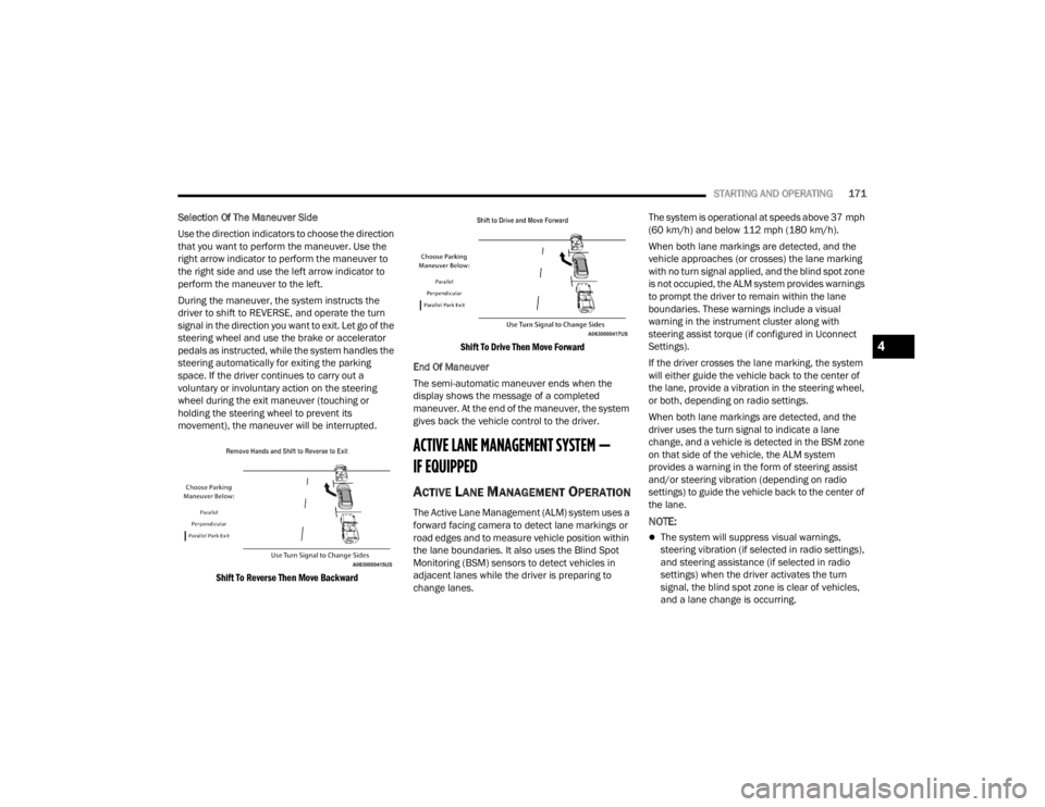
During the maneuver, the system instructs the
driver to shift to REVERSE, and operate the turn
signal in the direction you want to exit. Let go of the
steering wheel and use the brake or accelerator
pedals as instructed, while the system handles the
steering automatically for exiting the parking
space. If the driver continues to carry out a
voluntary or involuntary action on the steering
wheel during the exit maneuver (touching or
holding the steering wheel to prevent its
movement), the maneuver will be interrupted.
Shift To Reverse Then Move Backward Shift To Drive Then Move Forward
End Of Maneuver
The semi-automatic maneuver ends when the
display shows the message of a completed
maneuver. At the end of the maneuver, the system
gives back the vehicle control to the driver.
ACTIVE LANE MANAGEMENT SYSTEM —
IF EQUIPPED
ACTIVE LANE MANAGEMENT OPERATION
The Active Lane Management (ALM) system uses a
forward facing camera to detect lane markings or
road edges and to measure vehicle position within
the lane boundaries. It also uses the Blind Spot
Monitoring (BSM) sensors to detect vehicles in
adjacent lanes while the driver is preparing to
change lanes. The system is operational at speeds above 37 mph
(60 km/h) and below 112 mph (180 km/h).
When both lane markings are detected, and the
vehicle approaches (or crosses) the lane marking
with no turn signal applied, and the blind spot zone
is not occupied, the ALM system provides warnings
to prompt the driver to remain within the lane
boundaries. These warnings include a visual
warning in the instrument cluster along with
steering assist torque (if configured in Uconnect
Settings).
If the driver crosses the lane marking, the system
will either guide the vehicle back to the center of
the lane, provide a vibration in the steering wheel,
or both, depending on radio settings.
When both lane markings are detected, and the
driver uses the turn signal to indicate a lane
change, and a vehicle is detected in the BSM zone
on that side of the vehicle, the ALM system
provides a warning in the form of steering assist
and/or steering vibration (depending on radio
settings) to guide the vehicle back to the center of
the lane.NOTE:
The system will suppress visual warnings,
steering vibration (if selected in radio settings),
and steering assistance (if selected in radio
settings) when the driver activates the turn
signal, the blind spot zone is clear of vehicles,
and a lane change is occurring.
4
23_WL_OM_EN_USC_t.book Page 171
Page 174 of 424
172STARTING AND OPERATING
If the Blind Spot Monitoring (BSM) system
detects a vehicle in the adjacent lane, and the
turn signal is applied in that direction, the BSM
LED on the mirror will flash. If the driver
continues to attempt the lane change, steering
wheel torque will be provided to keep the
vehicle within its lane markings.
The driver may manually override the steering
assist warning by applying force to the steering
wheel at any time.
When only a single lane marking is detected and
the driver drifts across the lane marking (no turn
signal applied), the Active Lane Management
system provides a visual warning in the instrument
cluster, as well as a steering assist torque (if
configured in Uconnect Settings), to prompt the
driver to remain within the lane boundaries. If the
driver continues to drift out of the lane, the system
provides a flashing visual warning through the
instrument cluster display as well as a haptic
steering wheel vibration (if configured in Uconnect
Settings) when the vehicle crosses the lane
boundary.
NOTE:When operating conditions have been met, the
Active Lane Management system will monitor if the
driver’s hands are on the steering wheel and
provides an audible and visual warning to the
driver if removed. The system will cancel if the
driver does not return their hands to the wheel.
TURNING ACTIVE LANE MANAGEMENT
O
N OR OFF
The Active Lane Management button is
located on the switch panel above the
Uconnect display.
To turn the system on, push the Active Lane
Management button (LED turns off). A message is
shown in the instrument cluster display.
To turn the system off, push the button again (LED
turns on).
NOTE:The Active Lane Management system will retain
the last system state on or off from the last ignition
cycle when the ignition is placed in the ON/RUN
position.
ACTIVE LANE MANAGEMENT WARNING
M
ESSAGE
The Active Lane Management system will indicate
the current lane drift condition through the
instrument cluster display.
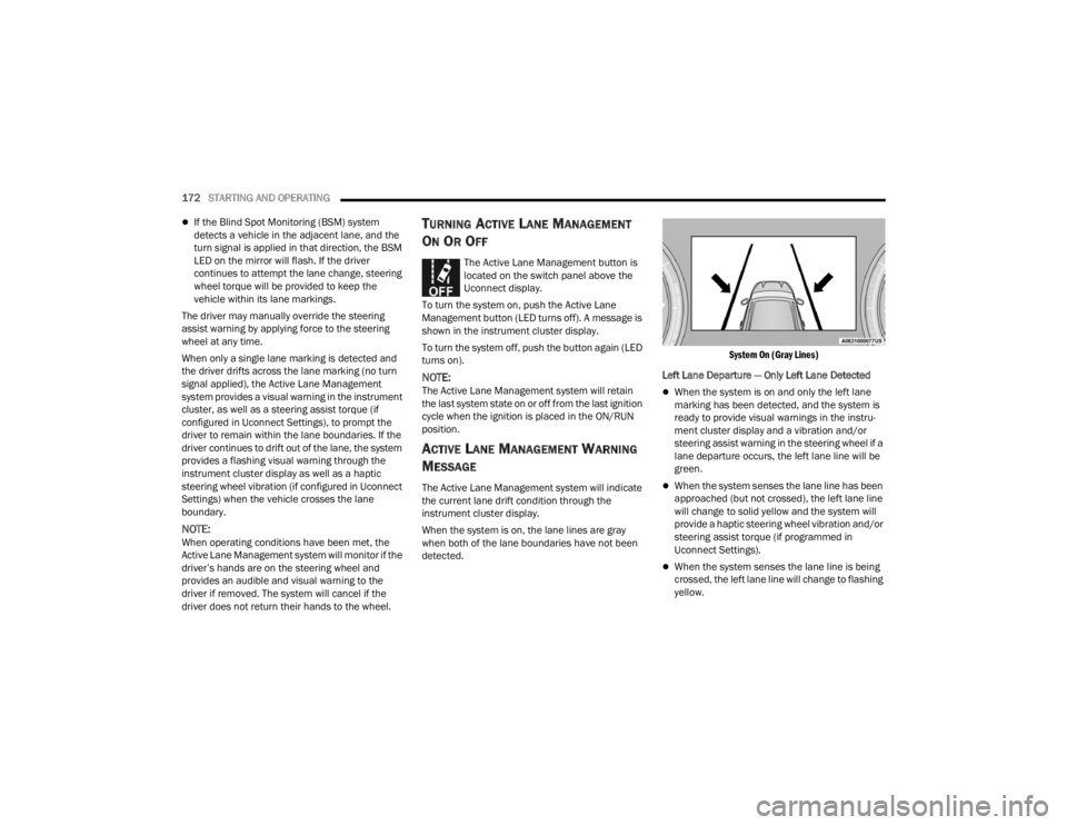
When the system is on, the lane lines are gray
when both of the lane boundaries have not been
detected.
System On (Gray Lines)
Left Lane Departure — Only Left Lane Detected
When the system is on and only the left lane
marking has been detected, and the system is
ready to provide visual warnings in the instru-
ment cluster display and a vibration and/or
steering assist warning in the steering wheel if a
lane departure occurs, the left lane line will be
green.
When the system senses the lane line has been
approached (but not crossed), the left lane line
will change to solid yellow and the system will
provide a haptic steering wheel vibration and/or
steering assist torque (if programmed in
Uconnect Settings).
When the system senses the lane line is being
crossed, the left lane line will change to flashing
yellow.
23_WL_OM_EN_USC_t.book Page 172
Page 176 of 424
174STARTING AND OPERATING
NOTE:
The Active Lane Management system operates
with similar behavior for a right lane departure.
If the turn signal is activated, and the vehicle
begins to depart the lane at the same time the
Blind Spot Monitoring (BSM) system detects
another vehicle in the BSM zones, the system
will provide a haptic steering wheel vibration
and/or steering assist torque (if programmed in
Uconnect Settings).
CHANGING ACTIVE LANE MANAGEMENT
S
TATUS
Configurable settings for the Active Lane
Management system are available within the
Uconnect system Ú page 204.
Selectable Warning Types:
Vibration Only
Steering Assist Only
Vibration And Steering Assist
Other configurable settings for this system are for
the intensity of the vibration (high/med/low),
steering assist warning (hi/med/low), and the
warning zone sensitivity (early/medium/late).
NOTE:
The system will not apply vibration and/or
steering assist to the steering wheel whenever a
safety system engages (Anti-Lock Brakes, Trac -
tion Control System, Electronic Stability Control,
Forward Collision Warning, etc.).
The Blind Spot Monitoring system will be forced
on when the ALM system is enabled.
The ALM system will be suppressed when the
Active Driving Assist system (if equipped) is
engaged.
PARKVIEW REAR BACK UP CAMERA
Your vehicle is equipped with the ParkView Rear
Back Up Camera that allows you to see an
on-screen image of the rear surroundings of your
vehicle whenever the gear selector is put into
REVERSE. The image will be displayed on the
Uconnect display screen along with a caution note
to “Check Entire Surroundings” across the top of
the screen. After five seconds this note will
disappear. The ParkView camera is located on the
rear of the vehicle above the rear license plate.
When the vehicle is shifted out of REVERSE with
camera delay turned off, the rear camera mode is
exited and the previous screen appears. Manual Activation Of The Back Up Camera
1. Press the Vehicle button located on the
bottom of the Uconnect display and then
select the Controls menu.
2. Press the Back Up Camera icon to turn the Rear View Camera system on.
NOTE:The ParkView Rear Back Up Camera has program -
mable modes of operation that may be selected
through the Uconnect system Ú page 204.
When the vehicle is shifted out of REVERSE with
camera delay turned off, the rear camera mode is
exited and the previous screen appears. When the
vehicle is shifted out of REVERSE with camera delay
turned on, the camera image will continue to be
displayed for up to 10 seconds unless the following
conditions occur: the vehicle speed exceeds 8 mph
(13 km/h), the vehicle is shifted into PARK, the
vehicle’s ignition is placed in the OFF position, or the
touchscreen X button to disable the display of the
Rear View Camera is pressed.
When enabled, active guidelines are overlaid on
the image to illustrate the width of the vehicle and
its projected backup path based on the steering
wheel position. A dashed center line overlay
indicates the center of the vehicle to assist with
parking or aligning to a hitch/receiver. Different
colored zones indicate the distance to the rear of
the vehicle.
23_WL_OM_EN_USC_t.book Page 174
Page 195 of 424
STARTING AND OPERATING193
Towing Requirements — Trailer Brakes
Do not interconnect the hydraulic brake system
or vacuum system of your vehicle with that of
the trailer. This could cause inadequate braking
and possible personal injury.
An electronically actuated trailer brake
controller is required when towing a trailer with
electronically actuated brakes. When towing a
trailer equipped with a hydraulic surge actuated
brake system, an electronic brake controller is
not required.
Trailer brakes are recommended for trailers
over 1,000 lb (453 kg) and required for trailers
in excess of 2,000 lb (907 kg).
Towing Requirements — Trailer Lights And
Wiring
Whenever pulling a trailer, regardless of the trailer
size, stop lights and turn signals on the trailer are
required for motoring safety.
The Trailer Tow Package may include a four- and
seven-pin wiring harness. Use a factory approved
trailer harness and connector.
NOTE:Do not cut or splice wiring into the vehicle’s wiring
harness.
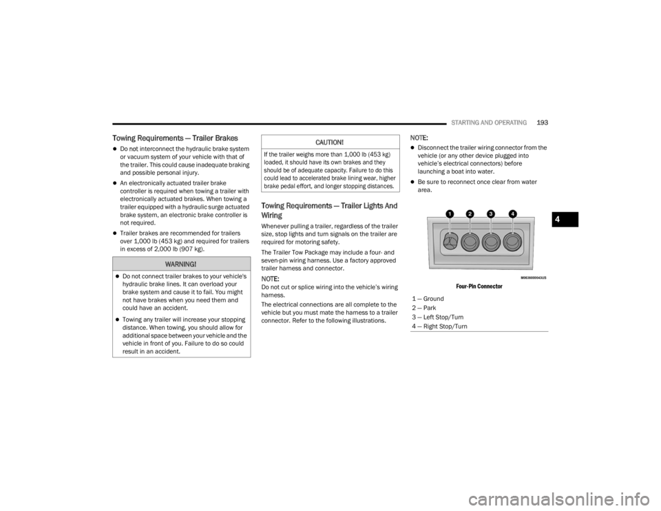
The electrical connections are all complete to the
vehicle but you must mate the harness to a trailer
connector. Refer to the following illustrations.
NOTE:
Disconnect the trailer wiring connector from the
vehicle (or any other device plugged into
vehicle’s electrical connectors) before
launching a boat into water.
Be sure to reconnect once clear from water
area.
Four-Pin Connector
WARNING!
Do not connect trailer brakes to your vehicle's
hydraulic brake lines. It can overload your
brake system and cause it to fail. You might
not have brakes when you need them and
could have an accident.
Towing any trailer will increase your stopping
distance. When towing, you should allow for
additional space between your vehicle and the
vehicle in front of you. Failure to do so could
result in an accident.
CAUTION!
If the trailer weighs more than 1,000 lb (453 kg)
loaded, it should have its own brakes and they
should be of adequate capacity. Failure to do this
could lead to accelerated brake lining wear, higher
brake pedal effort, and longer stopping distances.
1 — Ground
2 — Park
3 — Left Stop/Turn
4 — Right Stop/Turn
4
23_WL_OM_EN_USC_t.book Page 193