ECO mode JEEP GRAND CHEROKEE 2023 Repair Manual
[x] Cancel search | Manufacturer: JEEP, Model Year: 2023, Model line: GRAND CHEROKEE, Model: JEEP GRAND CHEROKEE 2023Pages: 424, PDF Size: 15.48 MB
Page 255 of 424
SAFETY253
The ESC Activation/Malfunction Indicator Light
starts to flash as soon as the tires lose traction and
the ESC system becomes active. The ESC
Activation/Malfunction Indicator Light also flashes
when TCS is active. If the ESC Activation/
Malfunction Indicator Light begins to flash during
acceleration, ease up on the accelerator and apply
as little throttle as possible. Be sure to adapt your
speed and driving to the prevailing road conditions. The ESC OFF Indicator Light indicates the
customer has elected to have the
Electronic Stability Control (ESC) in a
reduced mode.
NOTE:
The ESC Activation/Malfunction Indicator Light
and the ESC OFF Indicator Light come on
momentarily each time the ignition is placed in
the ON/RUN mode.
Each time the ignition is placed in the ON/RUN
mode, the ESC system will be on even if it was
turned off previously.
The ESC system will make buzzing or clicking
sounds when it is active. This is normal; the
sounds will stop when ESC becomes inactive
following the maneuver that caused the ESC
activation.
Hill Descent Control (HDC) — If Equipped
HDC is intended for low speed off-road
driving while in 4WD Low. HDC maintains
vehicle speed while descending hills
during various driving situations. HDC
controls vehicle speed by actively controlling the
brakes.
HDC Has Three States:
1. Off (feature is not enabled and will not activate).
2. Enabled (feature is enabled and ready but activation conditions are not met, or driver is
actively overriding with brake or throttle
application).
3. Active (feature is enabled and actively controlling vehicle speed).
Enabling HDC
HDC is enabled by pushing the HDC switch, but the
following conditions must also be met to enable
HDC:
The driveline is in 4WD Low.
The vehicle speed is below 5 mph (8 km/h).
The parking brake is released.
The driver door is closed. Activating HDC
Once HDC is enabled it will activate automatically
if driven down a grade of sufficient magnitude. The
set speed for HDC is selectable by the driver, and
can be adjusted by using the gear shift +/-. The
following summarizes the HDC set speeds:
HDC Target Set Speeds
P = No set speed. HDC may be enabled but will
not activate.
R = 0.6 mph (1 km/h)
N = 1.2 mph (2 km/h)
D = 0.6 mph (1 km/h)
1st = 0.6 mph (1 km/h)
2nd = 1.2 mph (2 km/h)
3rd = 1.8 mph (3 km/h)
4th = 2.5 mph (4 km/h)
5th = 3.1 mph (5 km/h)
6th = 3.7 mph (6 km/h)
7th = 4.3 mph (7 km/h)
8th = 5.0 mph (8 km/h)
NOTE:During HDC the +/- shifter input is used for HDC
target speed selection, but will not affect the gear
chosen by the transmission. When actively
controlling HDC the transmission will shift appro
-
priately for the driver-selected set speed and corre -
sponding driving conditions.
6
23_WL_OM_EN_USC_t.book Page 253
Page 258 of 424
256SAFETY
Enabling SSC
SSC is enabled by pushing the SSC switch, but the
following conditions must also be met to enable
SSC:
The driveline is in 4WD Low.
The vehicle speed is below 5 mph (8 km/h).
The parking brake is released.
The driver door is closed.
The driver is not applying throttle.
Activating SSC
Once SSC is enabled it will activate automatically
once the following conditions are met:
The driver releases the throttle.
The driver releases the brake.
The transmission is in any selection other than
PARK.
The vehicle speed is below 20 mph (32 km/h).
The set speed for SSC is selectable by the driver,
and can be adjusted by using the gear shift +/-.
Additionally, the SSC set speed may be reduced
when climbing a grade and the level of set speed
reduction depends on the magnitude of grade. The
following summarizes the SSC set speeds: SSC Target Set Speeds
1st = .6 mph (1 km/h)
2nd = 1.2 mph (2 km/h)
3rd = 1.8 mph (3 km/h)
4th = 2.5 mph (4 km/h)
5th = 3.1 mph (5 km/h)
6th = 3.7 mph (6 km/h)
7th = 4.3 mph (7 km/h)
8th = 5 mph (8 km/h)
9th = 5.6 mph (9 km/h) – if equipped
REVERSE = .6 mph (1 km/h)
NEUTRAL = 1.2 mph (2 km/h)
PARK = SSC remains enabled but not active
NOTE:
During SSC the +/- shifter input is used for SSC
target speed selection but will not affect the
gear chosen by the transmission. While actively
controlling SSC the transmission will shift appro
-
priately for the driver-selected set speed and
corresponding driving conditions.
SSC operation is influenced by Off Road+ drive
mode if active. The differences may be notable
to the driver as a varying level of aggressive -
ness. Driver Override:
The driver may override SSC activation with throttle
or brake application at any time.
Deactivating SSC
SSC will be deactivated but remain available if any
of the following conditions occur:
Driver overrides SSC set speed with throttle or
brake application
Vehicle speed exceeds 20 mph (32 km/h) but
remains below 40 mph (64 km/h)
Vehicle is shifted to PARK
Disabling SSC
SSC will deactivate and be disabled if any of the
following conditions occur:
The driver pushes the SSC switch.
The driveline is shifted out of 4WD Low.
The parking brake is applied.
The driver door opens.
The vehicle is driven greater than 20 mph
(32 km/h) for greater than 70 seconds.
The vehicle is driven greater than 40 mph
(64 km/h) (SSC exits immediately).
23_WL_OM_EN_USC_t.book Page 256
Page 259 of 424
SAFETY257
Feedback To The Driver:
The instrument cluster has an SSC icon and the
SSC switch has an LED which offer feedback to the
driver about the state SSC is in.
The cluster icon and switch light will illuminate
and remain on solid when SSC is enabled or
activated. This is the normal operating condition
for SSC.
The cluster icon and switch light will flash for
several seconds then extinguish when the driver
pushes the SSC switch but enable conditions
are not met.
The cluster icon and switch light will flash for
several seconds then extinguish when SSC
disables due to excess speed.
The cluster icon and switch light will flash then
extinguish when SSC deactivates due to over -
heated brakes.
Traction Control System (TCS)
The TCS monitors the amount of wheel spin of
each of the driven wheels. If wheel spin is
detected, the TCS may apply brake pressure to the
spinning wheel(s) and/or reduce engine power to
provide enhanced acceleration and stability. A
feature of the TCS, Brake Limited Differential (BLD)
functions similarly to a limited slip differential and
controls the wheel spin across a driven axle. If one
wheel on a driven axle is spinning faster than the
other, the system will apply the brake of the
spinning wheel. This will allow more engine power
to be applied to the wheel that is not spinning. BLD
may remain enabled even if TCS and Electronic
Stability Control (ESC) are in reduced modes.
Trailer Sway Control (TSC)
TSC uses sensors in the vehicle to recognize an
excessively swaying trailer and will take the
appropriate actions to attempt to stop the sway.
TSC will become active automatically once an
excessively swaying trailer is recognized.
NOTE:TSC cannot stop all trailers from swaying. Always
use caution when towing a trailer and follow the
trailer tongue weight recommendations
Ú page 185.
When TSC is functioning, the ESC Activation/
Malfunction Indicator Light will flash, the engine
power may be reduced and you may feel the
brakes being applied to individual wheels to
attempt to stop the trailer from swaying. TSC is
disabled when the ESC system is in the “Partial
Off” mode.
WARNING!
SSC is only intended to assist the driver in
controlling vehicle speed when driving in off
road conditions. The driver must remain
attentive to the driving conditions and is
responsible for maintaining a safe vehicle
speed.
WARNING!
If TSC activates while driving, slow the vehicle
down, stop at the nearest safe location, and
adjust the trailer load to eliminate trailer sway.6
23_WL_OM_EN_USC_t.book Page 257
Page 270 of 424
268SAFETY
Beginning with the next ignition cycle, the TPMS
will no longer chime or display the “SERVICE TPM
SYSTEM” message in the instrument cluster but
dashes (--) will remain in place of the pressure
values.
To reactivate the TPMS, replace all four wheel and
tire assemblies (road tires) with tires equipped with
TPMS sensors. Then, drive the vehicle for up to
20 minutes above 15 mph (24 km/h). The TPMS
will chime, the TPMS Warning Light will flash on
and off for 75 seconds and then turn off. The
instrument cluster will display the “SERVICE TPM
SYSTEM” message and then display pressure
values in place of the dashes. On the next ignition
cycle the "SERVICE TPM SYSTEM" message will no
longer be displayed as long as no system fault
exists.
Tire Fill Alert
This feature notifies the user when the placard tire
pressure is attained while inflating or deflating the
tire.
The customer may choose to disable or enable the
Tire Fill Alert feature in the apps menu of the
Uconnect system.
NOTE:
The Tire Fill Alert system will only support
inflating or deflating one tire at a time. The user
is required to wait until the hazard lights STOP flashing or 26-30 seconds after the desired
pressure is achieved in one wheel before
switching to another.
The Tire Fill Alert feature cannot be entered if an
existing TPMS fault is set to “active” or if the
system is in deactivation mode (if equipped).
The system will be activated when the system
detects an increase in tire pressure while filling the
tire. The ignition must be in the ON/RUN mode with
the transmission in PARK for vehicles equipped
with an automatic transmission. For vehicles
equipped with a manual transmission, the parking
brake must be applied.
NOTE:It is not required to have the engine running to
enter Tire Fill Alert mode.
The hazard lamps will come on to confirm the
vehicle is in Tire Fill Alert mode. If the hazard lamps
do not come on while inflating the tire, the Tire
Pressure Monitoring System sensor may be in an
inoperative position, preventing the TPMS sensor
signal from being received. In this case, the vehicle
may need to be moved slightly forward or
backward.
When Tire Fill Alert mode is entered, the tire
pressure display screen will be displayed in the
instrument cluster. Operation:
The horn will chirp once to let the user know
when to stop filling the tire, when it reaches
recommended pressure.
The horn will chirp three times if the tire is over
-
filled and will continue to chirp every five
seconds if the user continues to inflate the tire.
The horn will chirp once again when enough air
is let out to reach proper inflation level.
The horn will also chirp three times if the tire is
then underinflated and will continue to chirp
every five seconds if the user continues to
deflate the tire.
Selectable Tire Fill Alert (STFA) —
If Equipped
The Selectable Tire Fill Alert (STFA) system is an
optional feature that is included as part of the
normal Tire Fill Alert system. The system is
designed to allow you to select a pressure to inflate
or deflate the vehicle's front and rear axle tires to,
and to provide feedback while inflating or deflating
the vehicle's tires.
23_WL_OM_EN_USC_t.book Page 268
Page 271 of 424
SAFETY269
In the Selectable Tire Fill Alert application, which is
located in the apps menu of the Uconnect system,
you will be able to select a pressure setting for both
the front and rear axle tire pressures by scrolling
through a pressure range from ≥15 psi to XX in
1 psi increments for each axle setting.
XX = the vehicle's cold placard pressure values for
the front and rear axles as shown on the vehicle
placard pressure label.
You may also store pressure values chosen for
each axle in the Uconnect system application as
preset pressure values. Up to two sets of preset
pressure values can be stored in the Uconnect
system for the front and rear axle. Once you select
the tire pressures for the front and rear axles that
you want to inflate or deflate to, you can begin
inflating or deflating one tire at a time.
NOTE:The STFA system will only support inflating or
deflating one tire at a time. The user is required to
wait until the hazard lights STOP flashing or 26-30
seconds after the desired pressure is achieved in
one wheel before switching to another.
The system will be activated when the TPMS
receiver module detects a change in tire pressure.
The ignition must be in the ON/RUN mode, with the
transmission in PARK in vehicles with an automatic
transmission, and in NEUTRAL with the parking
brake engaged in vehicles with a manual transmission. The hazard lamps will come on to
confirm the vehicle is in Tire Fill Alert mode.
When Tire Fill Alert mode is entered, the tire
pressure screen will be displayed in the instrument
cluster. If the hazard lamps do not come on while
inflating or deflating the tire, the Tire Pressure
Monitoring System sensor may be in an
inoperative position, preventing the TPMS sensor
signal from being received. In this case, the vehicle
may need to be moved slightly forward or
backward.
Horn chirps will indicate STFA status as tires are
inflated/deflated. The horn will chirp under the
following STFA states:
1. The horn will chirp once when the selected
pressure is reached to let you know when to
stop inflating or deflating the tire.
2. The horn will chirp three times if the tire is overinflated or over-deflated.
3. The horn will chirp once again when enough air is added or removed to reach proper selected
pressure level.
OCCUPANT RESTRAINT SYSTEMS
Some of the most important safety features in your
vehicle are the restraint systems:
OCCUPANT RESTRAINT SYSTEMS
F
EATURES
Seat Belt Systems
Supplemental Restraint Systems (SRS) Air Bags
Child Restraints
Some of the safety features described in this
section may be standard equipment on some
models, or may be optional equipment on others. If
you are not sure, ask an authorized dealer.
IMPORTANT SAFETY PRECAUTIONS
Please pay close attention to the information in
this section. It tells you how to use your restraint
system properly, to keep you and your passengers
as safe as possible.
Here are some simple steps you can take to
minimize the risk of harm from a deploying air bag:
1. Children 12 years old and under should always ride buckled up in the rear seat of a
vehicle with a rear seat.
2. A child who is not big enough to wear the vehicle seat belt properly must be secured in
the appropriate child restraint or
belt-positioning booster seat in a rear seating
position Ú page 289.
6
23_WL_OM_EN_USC_t.book Page 269
Page 278 of 424
276SAFETY
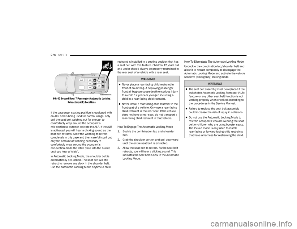
60/40 Second Row (7 Passenger) Automatic Locking Retractor (ALR) Locations
If the passenger seating position is equipped with
an ALR and is being used for normal usage, only
pull the seat belt webbing out far enough to
comfortably wrap around the occupant’s
mid-section so as to not activate the ALR. If the ALR
is activated, you will hear a clicking sound as the
seat belt retracts. Allow the webbing to retract
completely in this case and then carefully pull out
only the amount of webbing necessary to
comfortably wrap around the occupant’s
mid-section. Slide the latch plate into the buckle
until you hear a "click”.
In Automatic Locking Mode, the shoulder belt is
automatically pre-locked. The seat belt will still
retract to remove any slack in the shoulder belt.
Use the Automatic Locking Mode anytime a child restraint is installed in a seating position that has
a seat belt with this feature. Children 12 years old
and under should always be properly restrained in
the rear seat of a vehicle with a rear seat.
How To Engage The Automatic Locking Mode
1. Buckle the combination lap and shoulder
belt.
2. Grab the shoulder portion and pull downward until the entire seat belt is extracted.
3. Allow the seat belt to retract. As the seat belt retracts, you will hear a clicking sound. This
indicates the seat belt is now in the Automatic
Locking Mode. How To Disengage The Automatic Locking Mode
Unbuckle the combination lap/shoulder belt and
allow it to retract completely to disengage the
Automatic Locking Mode and activate the vehicle
sensitive (emergency) locking mode.
WARNING!
Never place a rear-facing child restraint in
front of an air bag. A deploying passenger
front air bag can cause death or serious injury
to a child 12 years or younger, including a
child in a rear-facing child restraint.
Never install a rear-facing child restraint in the
front seat of a vehicle. Only use a rear-facing
child restraint in the rear seat. If the vehicle
does not have a rear seat, do not transport a
rear-facing child restraint in that vehicle.
WARNING!
The seat belt assembly must be replaced if the
switchable Automatic Locking Retractor (ALR)
feature or any other seat belt function is not
working properly when checked according to
the procedures in the Service Manual.
Failure to replace the seat belt assembly
could increase the risk of injury in collisions.
Do not use the Automatic Locking Mode to
restrain occupants who are wearing the seat
belt or children who are using booster seats.
The locked mode is only used to install
rear-facing or forward-facing child restraints
that have a harness for restraining the child.
23_WL_OM_EN_USC_t.book Page 276
Page 285 of 424
SAFETY283
The Air Bag Warning Light in the instrument
panel will turn on whenever the OCS is unable to
classify the front passenger seat status. A
malfunction in the OCS may affect the operation of
the air bag system.
If the Air Bag Warning Light does not come on,
or stays on after you start the vehicle, or it comes
on as you drive, take the vehicle to an authorized
dealer for service immediately.
The passenger seat assembly contains critical OCS
components that may affect the Passenger
Advanced Front Air Bag inflation. In order for the
OCS to properly classify the seated weight of a
front seat passenger, the OCS components must
function as designed. Do not make any
modifications to the front passenger seat
components, assembly, or to the seat cover. If the
seat, trim cover, or cushion needs service for any
reason, take the vehicle to an authorized dealer.
Only FCA US LLC approved seat accessories may
be used.
The following requirements must be strictly
followed:
Do not modify the front passenger seat
assembly or components in any way.
Do not use prior or future model year seat
covers or cushions not designated by FCA US
LLC for the specific model being repaired. Always use the correct seat cover and cushion
specified for the vehicle.
Do not replace the seat cover or cushion with an
aftermarket seat cover or cushion.
Do not add a secondary seat cover or mat.
At no time should any Supplemental Restraint
System (SRS) component or SRS related
component or fastener be modified or replaced
with any part except those which are approved
by FCA US LLC.
WARNING!
If a child restraint system, child, small teen
-
ager or adult in the front passenger seat is
seated improperly, the occupant may provide
an output signal to the OCS that is different
from the occupant’s properly seated weight
input. This may result in serious injury or death
in a collision.
Always wear your seat belt and sit properly,
with the seatback in an upright position, your
back against the seatback, sitting upright,
facing forward, in the center of the seat, with
your feet comfortably on or near the floor.
Do not carry or hold any objects (e.g., back -
packs, boxes, etc.) while seated in the front
passenger seat. Holding an object may
provide an output signal to the OCS that is
different than the occupant’s properly seated
weight input, which may result in serious injury
or death in a collision.
Placing an object on the floor under the front
passenger seat may prevent the OCS from
working properly, which may result in serious
injury or death in a collision. Do not place any
objects on the floor under the front passenger
seat.
WARNING!
Unapproved modifications or service proce-
dures to the passenger seat assembly, its
related components, seat cover or cushion
may inadvertently change the air bag deploy -
ment in case of a frontal collision. This could
result in death or serious injury to the front
passenger if the vehicle is involved in a colli -
sion. A modified vehicle may not comply with
required Federal Motor Vehicle Safety Stan -
dards (FMVSS) and/or Canadian Motor
Vehicle Safety Standards (CMVSS).
If it is necessary to modify the air bag system
for persons with disabilities, contact an autho -
rized dealer.
6
23_WL_OM_EN_USC_t.book Page 283
Page 302 of 424
300SAFETY
Installing A Child Restraint With A
Switchable Automatic Locking Retractor
(ALR):
Child restraint systems are designed to be secured
in vehicle seats by lap belts or the lap belt portion
of a lap/shoulder belt.
1. Place the child seat in the center of the
seating position. If the second row seat can
be reclined, you may recline the seat and/or
raise the head restraint (if adjustable) to get a
better fit. If the rear seat can be moved
forward and rearward in the vehicle, you may
wish to move it to its rear-most position to
make room for the child seat. You may also
move the front seat forward to allow more
room for the child seat.
2. Pull enough of the seat belt webbing from the
retractor to pass it through the belt path of the
child restraint. Do not twist the belt webbing in
the belt path.
3. Slide the latch plate into the buckle until you hear a “click.”
4. Pull on the webbing to make the lap portion tight against the child seat.
5. To lock the seat belt, pull down on the shoulder part of the belt until you have pulled all the
seat belt webbing out of the retractor. Then,
allow the webbing to retract back into the
retractor. As the webbing retracts, you will hear
a clicking sound. This means the seat belt is
now in the Automatic Locking mode.
6. Try to pull the webbing out of the retractor. If it is locked, you should not be able to pull out any
webbing. If the retractor is not
locked, repeat
step 5.
7. Finally, pull up on any excess webbing to tighten the lap portion around the child
restraint while you push the child restraint
rearward and downward into the vehicle seat.
8. If the child restraint has a top tether strap and the seating position has a top tether
anchorage, connect the tether strap to the
anchorage and tighten the tether strap. See
Úpage 300 for directions to attach a tether
anchor. 9. Test that the child restraint is installed tightly
by pulling back and forth on the child seat at
the belt path. It should not move more than
1 inch (25.4 mm) in any direction.
Any seat belt system will loosen with time, so check
the belt occasionally, and pull it tight if necessary.
Installing Child Restraints Using The Top
Tether AnchorageWARNING!
Improper installation or failure to properly
secure a child restraint can lead to failure of
the restraint. The child could be badly injured
or killed.
Follow the child restraint manufacturer’s
directions exactly when installing an infant or
child restraint.
WARNING!
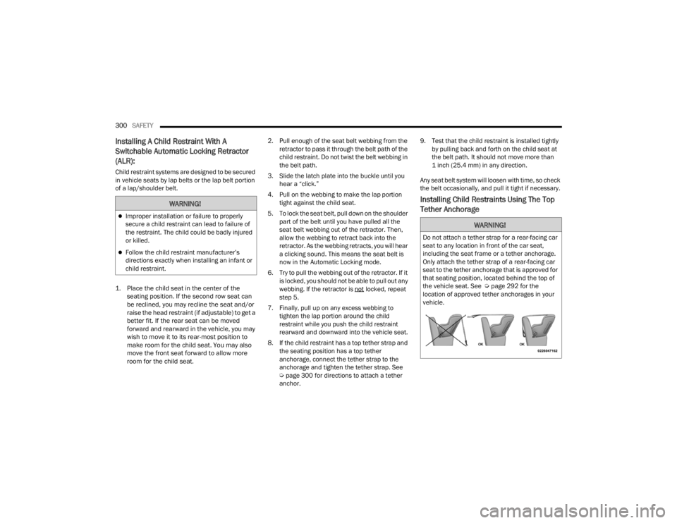
Do not attach a tether strap for a rear-facing car
seat to any location in front of the car seat,
including the seat frame or a tether anchorage.
Only attach the tether strap of a rear-facing car
seat to the tether anchorage that is approved for
that seating position, located behind the top of
the vehicle seat. See Ú page 292 for the
location of approved tether anchorages in your
vehicle.
23_WL_OM_EN_USC_t.book Page 300
Page 306 of 424
304SAFETY
(Continued)
(Continued)
(Continued)
Defroster
Check operation by selecting the defrost mode and
place the blower control on high speed. You should
be able to feel the air directed against the
windshield. See an authorized dealer for service if
your defroster is inoperable.
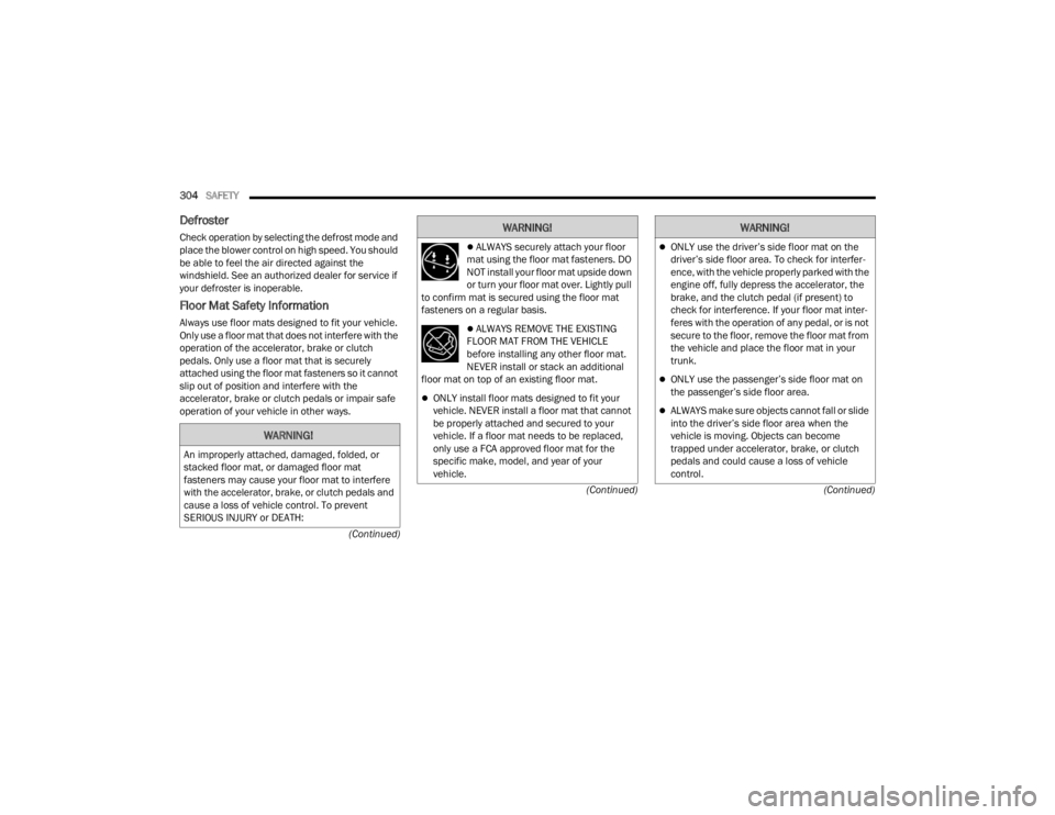
Floor Mat Safety Information
Always use floor mats designed to fit your vehicle.
Only use a floor mat that does not interfere with the
operation of the accelerator, brake or clutch
pedals. Only use a floor mat that is securely
attached using the floor mat fasteners so it cannot
slip out of position and interfere with the
accelerator, brake or clutch pedals or impair safe
operation of your vehicle in other ways.
WARNING!
An improperly attached, damaged, folded, or
stacked floor mat, or damaged floor mat
fasteners may cause your floor mat to interfere
with the accelerator, brake, or clutch pedals and
cause a loss of vehicle control. To prevent
SERIOUS INJURY or DEATH:
ALWAYS securely attach your floor
mat using the floor mat fasteners. DO
NOT install your floor mat upside down
or turn your floor mat over. Lightly pull
to confirm mat is secured using the floor mat
fasteners on a regular basis.
ALWAYS REMOVE THE EXISTING
FLOOR MAT FROM THE VEHICLE
before installing any other floor mat.
NEVER install or stack an additional
floor mat on top of an existing floor mat.
ONLY install floor mats designed to fit your
vehicle. NEVER install a floor mat that cannot
be properly attached and secured to your
vehicle. If a floor mat needs to be replaced,
only use a FCA approved floor mat for the
specific make, model, and year of your
vehicle.
WARNING!
ONLY use the driver’s side floor mat on the
driver’s side floor area. To check for interfer -
ence, with the vehicle properly parked with the
engine off, fully depress the accelerator, the
brake, and the clutch pedal (if present) to
check for interference. If your floor mat inter -
feres with the operation of any pedal, or is not
secure to the floor, remove the floor mat from
the vehicle and place the floor mat in your
trunk.
ONLY use the passenger’s side floor mat on
the passenger’s side floor area.
ALWAYS make sure objects cannot fall or slide
into the driver’s side floor area when the
vehicle is moving. Objects can become
trapped under accelerator, brake, or clutch
pedals and could cause a loss of vehicle
control.
WARNING!
23_WL_OM_EN_USC_t.book Page 304
Page 307 of 424
SAFETY305
PERIODIC SAFETY CHECKS YOU SHOULD
M
AKE OUTSIDE THE VEHICLE
Tires
Examine tires for excessive tread wear and uneven
wear patterns. Check for stones, nails, glass, or
other objects lodged in the tread or sidewall.
Inspect the tread for cuts and cracks. Inspect
sidewalls for cuts, cracks, and bulges. Check the
lug nut/bolt torque for tightness. Check the tires
(including spare) for proper cold inflation pressure.
Lights
Have someone observe the operation of brake
lights and exterior lights while you work the
controls. Check turn signal and high beam
indicator lights on the instrument panel.
Door Latches
Check for proper closing, latching, and locking.
Fluid Leaks
Check area under the vehicle after overnight
parking for fuel, coolant, oil, or other fluid leaks.
Also, if gasoline fumes are detected or if fuel or
brake fluid leaks are suspected, the cause should
be located and corrected immediately.
EXHAUST GAS
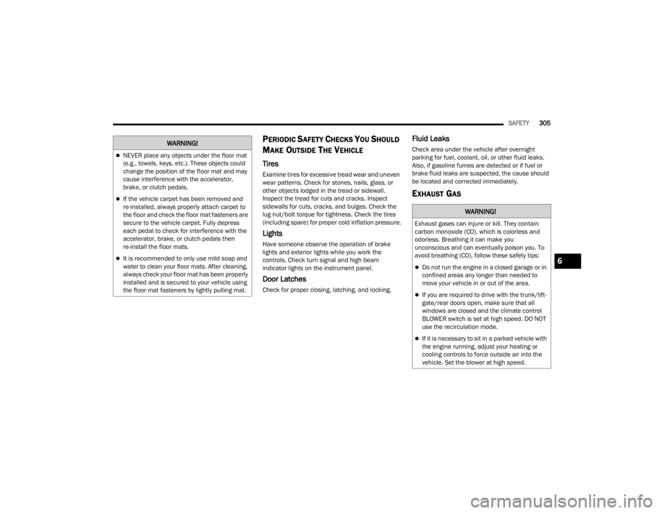
NEVER place any objects under the floor mat
(e.g., towels, keys, etc.). These objects could
change the position of the floor mat and may
cause interference with the accelerator,
brake, or clutch pedals.
If the vehicle carpet has been removed and
re-installed, always properly attach carpet to
the floor and check the floor mat fasteners are
secure to the vehicle carpet. Fully depress
each pedal to check for interference with the
accelerator, brake, or clutch pedals then
re-install the floor mats.
It is recommended to only use mild soap and
water to clean your floor mats. After cleaning,
always check your floor mat has been properly
installed and is secured to your vehicle using
the floor mat fasteners by lightly pulling mat.
WARNING!
WARNING!
Exhaust gases can injure or kill. They contain
carbon monoxide (CO), which is colorless and
odorless. Breathing it can make you
unconscious and can eventually poison you. To
avoid breathing (CO), follow these safety tips:
Do not run the engine in a closed garage or in
confined areas any longer than needed to
move your vehicle in or out of the area.
If you are required to drive with the trunk/lift -
gate/rear doors open, make sure that all
windows are closed and the climate control
BLOWER switch is set at high speed. DO NOT
use the recirculation mode.
If it is necessary to sit in a parked vehicle with
the engine running, adjust your heating or
cooling controls to force outside air into the
vehicle. Set the blower at high speed.
6
23_WL_OM_EN_USC_t.book Page 305