tow JEEP GRAND CHEROKEE 2023 Repair Manual
[x] Cancel search | Manufacturer: JEEP, Model Year: 2023, Model line: GRAND CHEROKEE, Model: JEEP GRAND CHEROKEE 2023Pages: 424, PDF Size: 15.48 MB
Page 290 of 424
288SAFETY
(Continued)
After an accident, if the vehicle will not start after
performing the reset procedure, the vehicle must
be towed to an authorized dealer to be inspected
and to have the Enhanced Accident Response
System reset.
Maintaining Your Air Bag System
Event Data Recorder (EDR)
This vehicle is equipped with an event data
recorder (EDR). The main purpose of an EDR is to
record, in certain crash or near crash-like
situations, such as an air bag deployment or hitting
a road obstacle, data that will assist in
understanding how a vehicle’s systems performed.
The EDR is designed to record data related to
vehicle dynamics and safety systems for a short
period of time, typically 30 seconds or less. The
EDR in this vehicle is designed to record such data
as:
How various systems in your vehicle were oper
-
ating;
Whether or not the driver and passenger safety
belts were buckled/fastened;
How far (if at all) the driver was depressing the
accelerator and/or brake pedal; and,
How fast the vehicle was traveling.
These data can help provide a better
understanding of the circumstances in which
crashes and injuries occur.
WARNING!
Modifications to any part of the air bag system
could cause it to fail when you need it. You
could be injured if the air bag system is not
there to protect you. Do not modify the compo -
nents or wiring, including adding any kind of
badges or stickers to the steering wheel hub
trim cover or the upper passenger side of the
instrument panel. Do not modify the front
fascia/bumper, vehicle body structure, or add
aftermarket side steps or running boards.
It is dangerous to try to repair any part of the
air bag system yourself. Be sure to tell anyone
who works on your vehicle that it has an air
bag system.
Do not attempt to modify any part of your air
bag system. The air bag may inflate acciden -
tally or may not function properly if modifica -
tions are made. Take your vehicle to an
authorized dealer for any air bag system
service. If your seat, including your trim cover
and cushion, needs to be serviced in any way
(including removal or loosening/tightening of
seat attachment bolts), take the vehicle to an
authorized dealer. Only manufacturer
approved seat accessories may be used. If it is
necessary to modify the air bag system for
persons with disabilities, contact an autho -
rized dealer.
WARNING!
23_WL_OM_EN_USC_t.book Page 288
Page 299 of 424
SAFETY297
Six Passenger Second Row Seating:
Seven Passenger Second Row Seating:
If a child restraint installed in the center position
blocks the seat belt webbing or buckle for the
outboard position, do not use that outboard
position. If a child seat in the center position blocks
the outboard LATCH anchors or seat belt, do not
install a child seat in that outboard position.
Always follow the directions of the child restraint
manufacturer when installing your child restraint.
Not all child restraint systems will be installed as
described here.
To Install A LATCH-Compatible Child
Restraint
If the selected seating position has a Switchable
Automatic Locking Retractor (ALR) seat belt, stow
the seat belt, following the instructions below. See
Ú page 298 to check what type of seat belt each
seating position has.
1. Loosen the adjusters on the lower straps and on the tether strap of the child seat so that
you can more easily attach the hooks or
connectors to the vehicle anchorages.
2. Place the child seat between the lower anchorages for that seating position. If the
second row seat can be reclined, you may
recline the seat and/or raise the head restraint
(if adjustable) to get a better fit. If the rear seat
can be moved forward and rearward in the
vehicle, you may wish to move it to its
rear-most position to make room for the child
seat. You may also move the front seat forward
to allow more room for the child seat.
3. Attach the lower hooks or connectors of the child restraint to the lower anchorages in the
selected seating position.
4. If the child restraint has a tether strap, connect it to the top tether anchorage. See
Úpage 300 for directions to attach a tether
anchor. 5. Tighten all of the straps as you push the child
restraint rearward and downward into the
seat. Remove slack in the straps according to
the child restraint manufacturer’s instructions.
6. Test that the child restraint is installed tightly by pulling back and forth on the child seat at
the belt path. It should not move more than
1 inch (25.4 mm) in any direction.
How To Stow An Unused Switchable-ALR
(ALR) Seat Belt:
When using the LATCH attaching system to install
a child restraint, stow all ALR seat belts that are not
being used by other occupants or being used to
secure child restraints. An unused belt could injure
a child if they play with it and accidentally lock the
seat belt retractor. Before installing a child
restraint using the LATCH system, buckle the seat
belt behind the child restraint and out of the child’s
reach. If the buckled seat belt interferes with the
child restraint installation, instead of buckling it
behind the child restraint, route the seat belt
through the child restraint belt path and then
buckle it. Do not lock the seat belt. Remind all
children in the vehicle that the seat belts are not
toys and that they should not play with them.
WARNING!
This vehicle does not have a center seating
position. Do not use the center lower LATCH
anchorages to install a child seat in the center of
the back seat.
WARNING!
Never use the same lower anchorage to attach
more than one child restraint. For typical
installation instructions, see Ú page 297.
6
23_WL_OM_EN_USC_t.book Page 297
Page 307 of 424
SAFETY305
PERIODIC SAFETY CHECKS YOU SHOULD
M
AKE OUTSIDE THE VEHICLE
Tires
Examine tires for excessive tread wear and uneven
wear patterns. Check for stones, nails, glass, or
other objects lodged in the tread or sidewall.
Inspect the tread for cuts and cracks. Inspect
sidewalls for cuts, cracks, and bulges. Check the
lug nut/bolt torque for tightness. Check the tires
(including spare) for proper cold inflation pressure.
Lights
Have someone observe the operation of brake
lights and exterior lights while you work the
controls. Check turn signal and high beam
indicator lights on the instrument panel.
Door Latches
Check for proper closing, latching, and locking.
Fluid Leaks
Check area under the vehicle after overnight
parking for fuel, coolant, oil, or other fluid leaks.
Also, if gasoline fumes are detected or if fuel or
brake fluid leaks are suspected, the cause should
be located and corrected immediately.
EXHAUST GAS
NEVER place any objects under the floor mat
(e.g., towels, keys, etc.). These objects could
change the position of the floor mat and may
cause interference with the accelerator,
brake, or clutch pedals.
If the vehicle carpet has been removed and
re-installed, always properly attach carpet to
the floor and check the floor mat fasteners are
secure to the vehicle carpet. Fully depress
each pedal to check for interference with the
accelerator, brake, or clutch pedals then
re-install the floor mats.
It is recommended to only use mild soap and
water to clean your floor mats. After cleaning,
always check your floor mat has been properly
installed and is secured to your vehicle using
the floor mat fasteners by lightly pulling mat.
WARNING!
WARNING!
Exhaust gases can injure or kill. They contain
carbon monoxide (CO), which is colorless and
odorless. Breathing it can make you
unconscious and can eventually poison you. To
avoid breathing (CO), follow these safety tips:
Do not run the engine in a closed garage or in
confined areas any longer than needed to
move your vehicle in or out of the area.
If you are required to drive with the trunk/lift -
gate/rear doors open, make sure that all
windows are closed and the climate control
BLOWER switch is set at high speed. DO NOT
use the recirculation mode.
If it is necessary to sit in a parked vehicle with
the engine running, adjust your heating or
cooling controls to force outside air into the
vehicle. Set the blower at high speed.
6
23_WL_OM_EN_USC_t.book Page 305
Page 310 of 424
308IN CASE OF EMERGENCY
(Continued)
ASSIST Call
The ASSIST Button is used to automatically
connect you to any one of the following support
centers:
Roadside Assistance – If you get a flat tire, or
need a tow, just push the ASSIST button and you
will be connected to a representative for assis-
tance. Roadside Assistance will know what
vehicle you’re driving and its location. Additional
fees may apply for roadside assistance.
Vehicle Customer Care – Total support for all
other vehicle issues.
Jeep® Connect Customer Care – Total support
for Radio, Phone and NAV issues.
SOS Call
1. Push the SOS Call button on the overhead console.
NOTE:In case the SOS Call button is pushed in error,
there will be a 10 second delay before the SOS Call
system initiates a call to a SOS operator. To cancel
the SOS Call connection, push the SOS call button
on the overhead console or press the cancellation
button on the Device Screen. Termination of the
SOS Call will turn off the green LED light on the
overhead console. 2. The LED light located within the ASSIST and
SOS buttons on the overhead console will turn
green once a connection to a SOS operator has
been made.
3. Once a connection between the vehicle and a SOS operator is made, the SOS Call system
may transmit the following important vehicle
information to a SOS operator:
Indication that the occupant placed a SOS
Call
The vehicle brand
The last known GPS coordinates of the
vehicle
4. You should be able to speak with the SOS operator through the vehicle audio system to
determine if additional assistance is needed.
NOTE:Once a connection is made between the vehicle’s
SOS Call system and the SOS operator, the SOS
operator may be able to open a voice connection
with the vehicle to determine if additional assis -
tance is needed. Once the SOS operator opens a
voice connection with the vehicle’s SOS Call
system, the operator should be able to speak with
you or other vehicle occupants and hear sounds
occurring in the vehicle. The vehicle’s SOS Call
system will attempt to remain connected with the
SOS operator until the SOS operator terminates
the connection.
5. The SOS operator may attempt to contact appropriate emergency responders and
provide them with important vehicle
information and GPS coordinates.
WARNING!
ALWAYS obey traffic laws and pay attention to
the road. ALWAYS drive safely with your hands on
the steering wheel. You have full responsibility
and assume all risks related to the use of the
features and applications in this vehicle. Only
use the features and applications when it is safe
to do so. Failure to do so may result in an
accident involving serious injury or death.
WARNING!
If anyone in the vehicle could be in danger
(e.g., fire or smoke is visible, dangerous road
conditions or location), do not wait for voice
contact from an Emergency Services Agent. All
occupants should exit the vehicle immediately
and move to a safe location.
23_WL_OM_EN_USC_t.book Page 308
Page 315 of 424
IN CASE OF EMERGENCY313
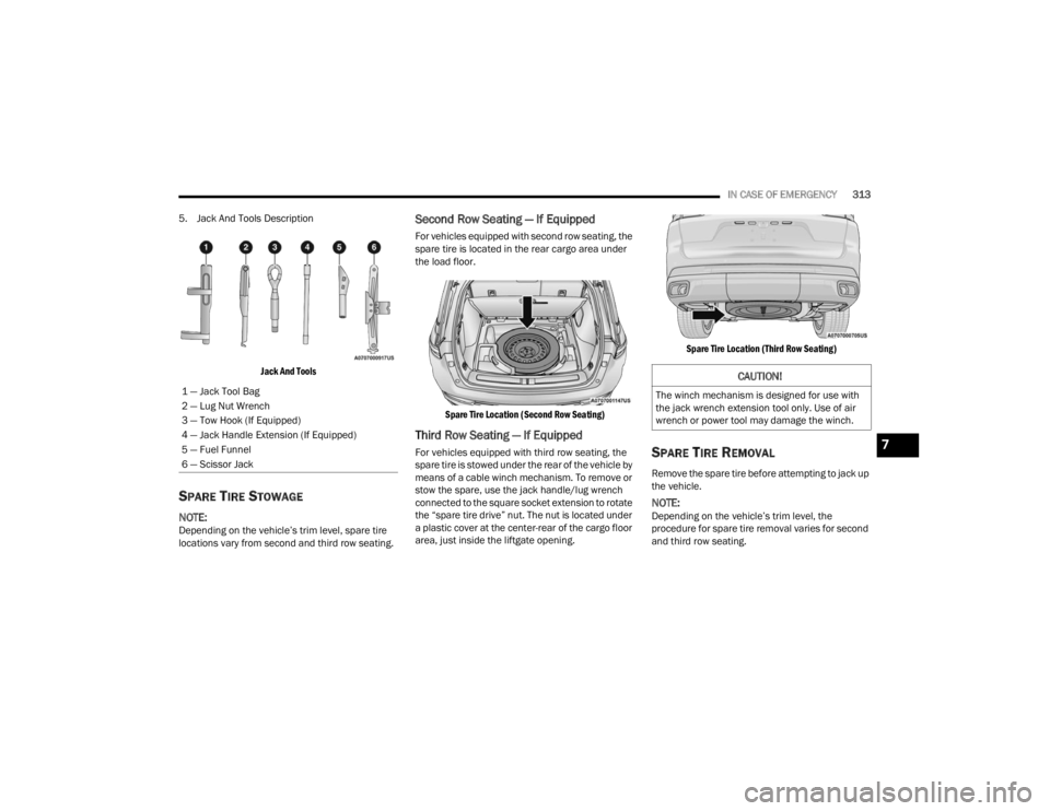
5. Jack And Tools Description
Jack And Tools
SPARE TIRE STOWAGE
NOTE:Depending on the vehicle’s trim level, spare tire
locations vary from second and third row seating.
Second Row Seating — If Equipped
For vehicles equipped with second row seating, the
spare tire is located in the rear cargo area under
the load floor.
Spare Tire Location (Second Row Seating)
Third Row Seating — If Equipped
For vehicles equipped with third row seating, the
spare tire is stowed under the rear of the vehicle by
means of a cable winch mechanism. To remove or
stow the spare, use the jack handle/lug wrench
connected to the square socket extension to rotate
the “spare tire drive” nut. The nut is located under
a plastic cover at the center-rear of the cargo floor
area, just inside the liftgate opening.
Spare Tire Location (Third Row Seating)
SPARE TIRE REMOVAL
Remove the spare tire before attempting to jack up
the vehicle.
NOTE:Depending on the vehicle’s trim level, the
procedure for spare tire removal varies for second
and third row seating.
1 — Jack Tool Bag
2 — Lug Nut Wrench
3 — Tow Hook (If Equipped)
4 — Jack Handle Extension (If Equipped)
5 — Fuel Funnel
6 — Scissor Jack
CAUTION!
The winch mechanism is designed for use with
the jack wrench extension tool only. Use of air
wrench or power tool may damage the winch.
7
23_WL_OM_EN_USC_t.book Page 313
Page 316 of 424
314IN CASE OF EMERGENCY
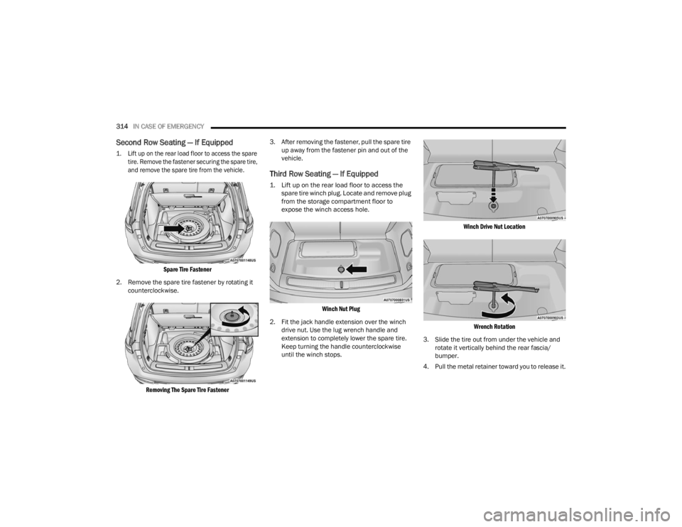
Second Row Seating — If Equipped
1. Lift up on the rear load floor to access the spare
tire. Remove the fastener securing the spare tire,
and remove the spare tire from the vehicle.
Spare Tire Fastener
2. Remove the spare tire fastener by rotating it counterclockwise.
Removing The Spare Tire Fastener
3. After removing the fastener, pull the spare tire
up away from the fastener pin and out of the
vehicle.
Third Row Seating — If Equipped
1. Lift up on the rear load floor to access the spare tire winch plug. Locate and remove plug
from the storage compartment floor to
expose the winch access hole.
Winch Nut Plug
2. Fit the jack handle extension over the winch drive nut. Use the lug wrench handle and
extension to completely lower the spare tire.
Keep turning the handle counterclockwise
until the winch stops.
Winch Drive Nut Location
Wrench Rotation
3. Slide the tire out from under the vehicle and rotate it vertically behind the rear fascia/
bumper.
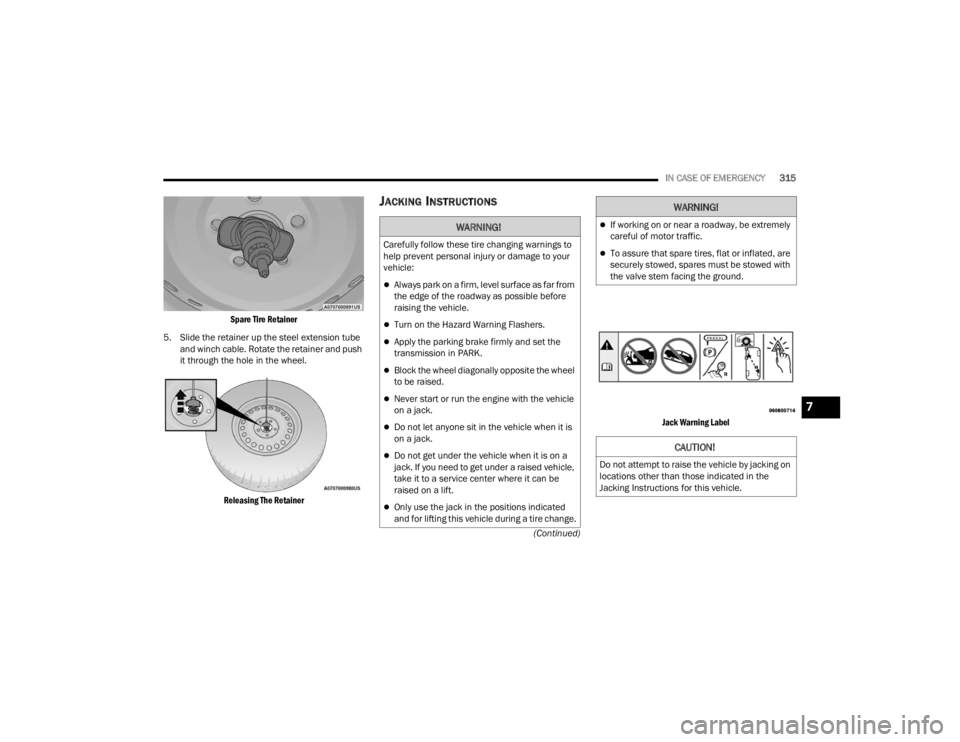
4. Pull the metal retainer toward you to release it.
23_WL_OM_EN_USC_t.book Page 314
Page 317 of 424
IN CASE OF EMERGENCY315
(Continued)
Spare Tire Retainer
5. Slide the retainer up the steel extension tube and winch cable. Rotate the retainer and push
it through the hole in the wheel.
Releasing The Retainer
JACKING INSTRUCTIONS
Jack Warning Label
WARNING!
Carefully follow these tire changing warnings to
help prevent personal injury or damage to your
vehicle:
Always park on a firm, level surface as far from
the edge of the roadway as possible before
raising the vehicle.
Turn on the Hazard Warning Flashers.
Apply the parking brake firmly and set the
transmission in PARK.
Block the wheel diagonally opposite the wheel
to be raised.
Never start or run the engine with the vehicle
on a jack.
Do not let anyone sit in the vehicle when it is
on a jack.
Do not get under the vehicle when it is on a
jack. If you need to get under a raised vehicle,
take it to a service center where it can be
raised on a lift.
Only use the jack in the positions indicated
and for lifting this vehicle during a tire change.
If working on or near a roadway, be extremely
careful of motor traffic.
To assure that spare tires, flat or inflated, are
securely stowed, spares must be stowed with
the valve stem facing the ground.
CAUTION!
Do not attempt to raise the vehicle by jacking on
locations other than those indicated in the
Jacking Instructions for this vehicle.
WARNING!
7
23_WL_OM_EN_USC_t.book Page 315
Page 319 of 424
IN CASE OF EMERGENCY317
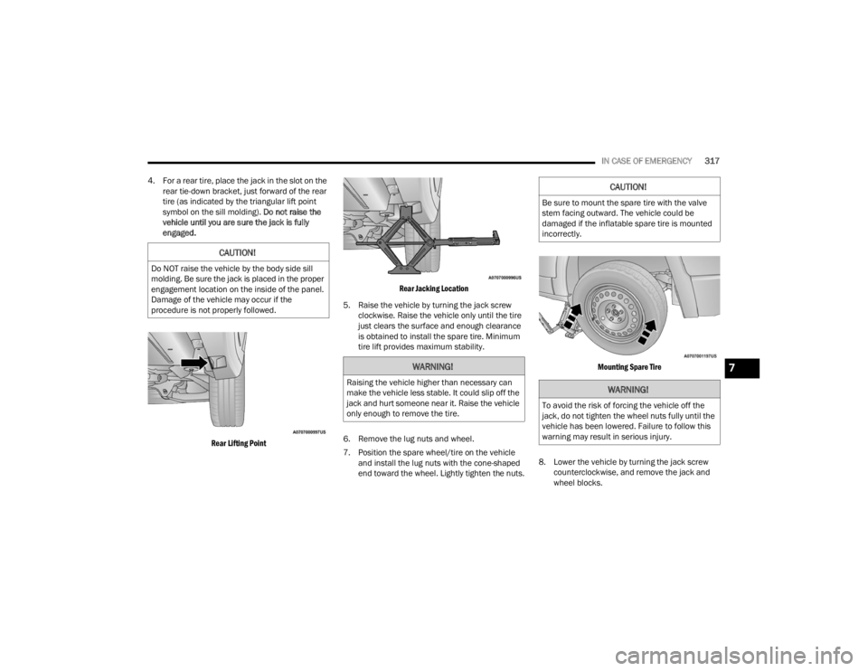
4. For a rear tire, place the jack in the slot on the rear tie-down bracket, just forward of the rear
tire (as indicated by the triangular lift point
symbol on the sill molding). Do not raise the
vehicle until you are sure the jack is fully
engaged.
Rear Lifting Point Rear Jacking Location
5. Raise the vehicle by turning the jack screw clockwise. Raise the vehicle only until the tire
just clears the surface and enough clearance
is obtained to install the spare tire. Minimum
tire lift provides maximum stability.
6. Remove the lug nuts and wheel.
7. Position the spare wheel/tire on the vehicle and install the lug nuts with the cone-shaped
end toward the wheel. Lightly tighten the nuts.
Mounting Spare Tire
8. Lower the vehicle by turning the jack screw counterclockwise, and remove the jack and
wheel blocks.
CAUTION!
Do NOT raise the vehicle by the body side sill
molding. Be sure the jack is placed in the proper
engagement location on the inside of the panel.
Damage of the vehicle may occur if the
procedure is not properly followed.
WARNING!
Raising the vehicle higher than necessary can
make the vehicle less stable. It could slip off the
jack and hurt someone near it. Raise the vehicle
only enough to remove the tire.
CAUTION!
Be sure to mount the spare tire with the valve
stem facing outward. The vehicle could be
damaged if the inflatable spare tire is mounted
incorrectly.
WARNING!
To avoid the risk of forcing the vehicle off the
jack, do not tighten the wheel nuts fully until the
vehicle has been lowered. Failure to follow this
warning may result in serious injury.
7
23_WL_OM_EN_USC_t.book Page 317
Page 320 of 424
318IN CASE OF EMERGENCY
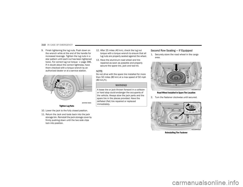
9. Finish tightening the lug nuts. Push down on the wrench while at the end of the handle for
increased leverage. Tighten the lug nuts in a
star pattern until each nut has been tightened
twice. For correct lug nut torque Úpage 396.
If in doubt about the correct tightness, have
them checked with a torque wrench by an
authorized dealer or at a service station.
Tighten Lug Nuts
10. Lower the jack to the fully closed position.
11. Return the Jack and tools back into the jack storage bin. Reinstall the jack storage cover by
firmly pushing down until the two side clips
lock into position. 12. After 25 miles (40 km), check the lug nut
torque with a torque wrench to ensure that all
lug nuts are properly seated against the wheel.
13. Have the aluminum road wheel and tire repaired as soon as possible and properly
secure the spare tire, jack and tool kit.
NOTE:Do not drive with the spare tire installed for more
than 50 miles (80 km) at a max speed of 50 mph
(80 km/h).
Second Row Seating — If Equipped
1. Securely store the road wheel in the cargo area.
Road Wheel Installed In Spare Tire Location
2. Turn the fastener clockwise until secured.
Reinstalling Tire Fastener
WARNING!
A loose tire or jack thrown forward in a collision
or hard stop could endanger the occupants of
the vehicle. Always stow the jack parts and the
spare tire in the places provided. Have the
deflated (flat) tire repaired or replaced
immediately.
23_WL_OM_EN_USC_t.book Page 318
Page 321 of 424
IN CASE OF EMERGENCY319
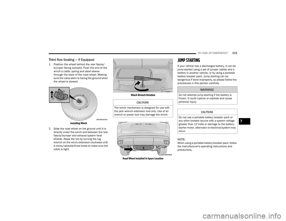
Third Row Seating — If Equipped
1. Position the wheel behind the rear fascia/
bumper facing outward. Push the end of the
winch’s cable, spring and steel sleeve
through the back of the road wheel. Making
sure the valve stem is facing the ground when
the wheel is stowed.
Installing Winch
2. Slide the road wheel on the ground until it is directly under the winch and between the rear
fascia/bumper and exhaust system heat
shields. Raise the tire by turning the lug
wrench on the winch extension clockwise until
it clicks/ratchets three times to make sure the
cable is tight.
Winch Wrench Rotation
Road Wheel Installed In Spare Location
JUMP STARTING
If your vehicle has a discharged battery, it can be
jump started using a set of jumper cables and a
battery in another vehicle, or by using a portable
battery booster pack. Jump starting can be
dangerous if done improperly, so please follow the
procedures in this section carefully.
NOTE:When using a portable battery booster pack, follow
the manufacturer's operating instructions and
precautions.
CAUTION!
The winch mechanism is designed for use with
the jack wrench extension tool only. Use of air
wrench or power tool may damage the winch.
WARNING!
Do not attempt jump starting if the battery is
frozen. It could rupture or explode and cause
personal injury.
CAUTION!
Do not use a portable battery booster pack or
any other booster source with a system voltage
greater than 12 Volts or damage to the battery,
starter motor, alternator or electrical system may
occur.
7
23_WL_OM_EN_USC_t.book Page 319