JEEP GRAND CHEROKEE LIMITED 2019 Owners Manual
GRAND CHEROKEE LIMITED 2019
JEEP
JEEP
https://www.carmanualsonline.info/img/16/56024/w960_56024-0.png
JEEP GRAND CHEROKEE LIMITED 2019 Owners Manual
Trending: checking oil, washer fluid, headlamp, transmission, gas type, run flat, auxiliary battery
Page 411 of 626
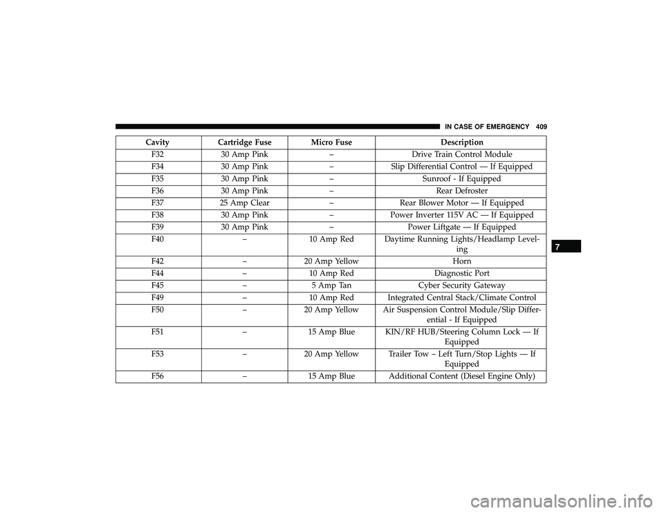
CavityCartridge Fuse Micro Fuse Description
F32 30 Amp Pink –Drive Train Control Module
F34 30 Amp Pink –Slip Differential Control — If Equipped
F35 30 Amp Pink –Sunroof - If Equipped
F36 30 Amp Pink –Rear Defroster
F37 25 Amp Clear –Rear Blower Motor — If Equipped
F38 30 Amp Pink –Power Inverter 115V AC — If Equipped
F39 30 Amp Pink –Power Liftgate — If Equipped
F40 –10 Amp Red Daytime Running Lights/Headlamp Level-
ing
F42 –20 Amp Yellow Horn
F44 –10 Amp Red Diagnostic Port
F45 –5 Amp Tan Cyber Security Gateway
F49 –10 Amp Red Integrated Central Stack/Climate Control
F50 –20 Amp Yellow Air Suspension Control Module/Slip Differ-
ential - If Equipped
F51 –15 Amp Blue KIN/RF HUB/Steering Column Lock — If
Equipped
F53 –20 Amp Yellow Trailer Tow – Left Turn/Stop Lights — If
Equipped
F56 –15 Amp Blue Additional Content (Diesel Engine Only)
7
IN CASE OF EMERGENCY 409
Page 412 of 626
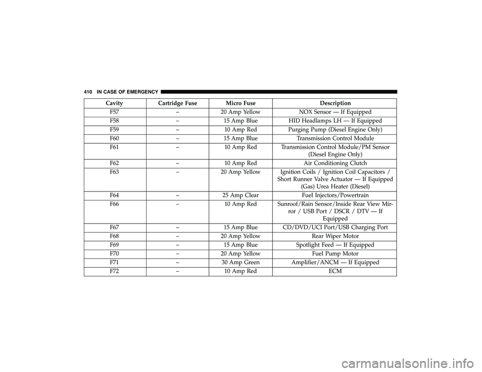
CavityCartridge Fuse Micro Fuse Description
F57 –20 Amp Yellow NOX Sensor — If Equipped
F58 –15 Amp Blue HID Headlamps LH — If Equipped
F59 –10 Amp Red Purging Pump (Diesel Engine Only)
F60 –15 Amp Blue Transmission Control Module
F61 –10 Amp Red Transmission Control Module/PM Sensor
(Diesel Engine Only)
F62 –10 Amp Red Air Conditioning Clutch
F63 –20 Amp Yellow Ignition Coils / Ignition Coil Capacitors /
Short Runner Valve Actuator — If Equipped(Gas) Urea Heater (Diesel)
F64 –25 Amp Clear Fuel Injectors/Powertrain
F66 –10 Amp Red Sunroof/Rain Sensor/Inside Rear View Mir-
ror / USB Port / DSCR / DTV — IfEquipped
F67 –15 Amp Blue CD/DVD/UCI Port/USB Charging Port
F68 –20 Amp Yellow Rear Wiper Motor
F69 –15 Amp Blue Spotlight Feed — If Equipped
F70 –20 Amp Yellow Fuel Pump Motor
F71 –30 Amp Green Amplifier/ANCM — If Equipped
F72 –10 Amp Red ECM
410 IN CASE OF EMERGENCY
Page 413 of 626
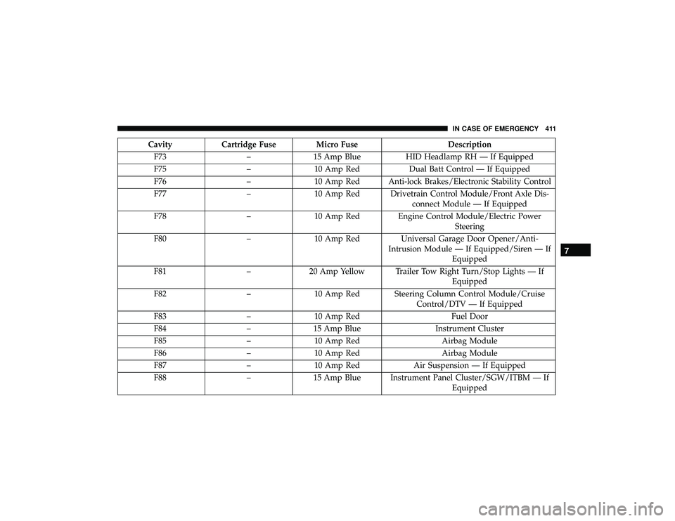
CavityCartridge Fuse Micro Fuse Description
F73 –15 Amp Blue HID Headlamp RH — If Equipped
F75 –10 Amp Red Dual Batt Control — If Equipped
F76 –10 Amp Red Anti-lock Brakes/Electronic Stability Control
F77 –10 Amp Red Drivetrain Control Module/Front Axle Dis-
connect Module — If Equipped
F78 –10 Amp Red Engine Control Module/Electric Power
Steering
F80 –10 Amp Red Universal Garage Door Opener/Anti-
Intrusion Module — If Equipped/Siren — If Equipped
F81 –20 Amp Yellow Trailer Tow Right Turn/Stop Lights — If
Equipped
F82 –10 Amp Red Steering Column Control Module/Cruise
Control/DTV — If Equipped
F83 –10 Amp Red Fuel Door
F84 –15 Amp Blue Instrument Cluster
F85 –10 Amp Red Airbag Module
F86 –10 Amp Red Airbag Module
F87 –10 Amp Red Air Suspension — If Equipped
F88 –15 Amp Blue Instrument Panel Cluster/SGW/ITBM — If
Equipped
7
IN CASE OF EMERGENCY 411
Page 414 of 626
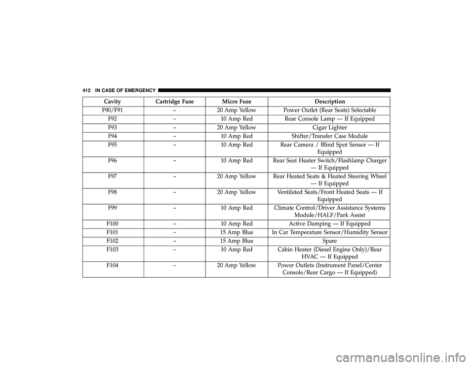
CavityCartridge Fuse Micro Fuse Description
F90/F91 –20 Amp Yellow Power Outlet (Rear Seats) Selectable
F92 –10 Amp Red Rear Console Lamp — If Equipped
F93 –20 Amp Yellow Cigar Lighter
F94 –10 Amp Red Shifter/Transfer Case Module
F95 –10 Amp Red Rear Camera / Blind Spot Sensor — If
Equipped
F96 –10 Amp Red Rear Seat Heater Switch/Flashlamp Charger
— If Equipped
F97 –20 Amp Yellow Rear Heated Seats & Heated Steering Wheel
— If Equipped
F98 –20 Amp Yellow Ventilated Seats/Front Heated Seats — If
Equipped
F99 –10 Amp Red Climate Control/Driver Assistance Systems
Module/HALF/Park Assist
F100 –10 Amp Red Active Damping — If Equipped
F101 –15 Amp Blue In Car Temperature Sensor/Humidity Sensor
F102 –15 Amp Blue Spare
F103 –10 Amp Red Cabin Heater (Diesel Engine Only)/Rear
HVAC — If Equipped
F104 –20 Amp Yellow Power Outlets (Instrument Panel/Center
Console/Rear Cargo — If Equipped)
412 IN CASE OF EMERGENCY
Page 415 of 626
CAUTION!
•When installing the power distribution center cover,
it is important to ensure the cover is properly posi-
tioned and fully latched. Failure to do so may allow
water to get into the power distribution center and
possibly result in an electrical system failure.
• When replacing a blown fuse, it is important to use
only a fuse having the correct amperage rating. The
use of a fuse with a rating other than indicated may
result in a dangerous electrical system overload. If a
properly rated fuse continues to blow, it indicates a
problem in the circuit that must be corrected.
JACKING AND TIRE CHANGING
Page 416 of 626
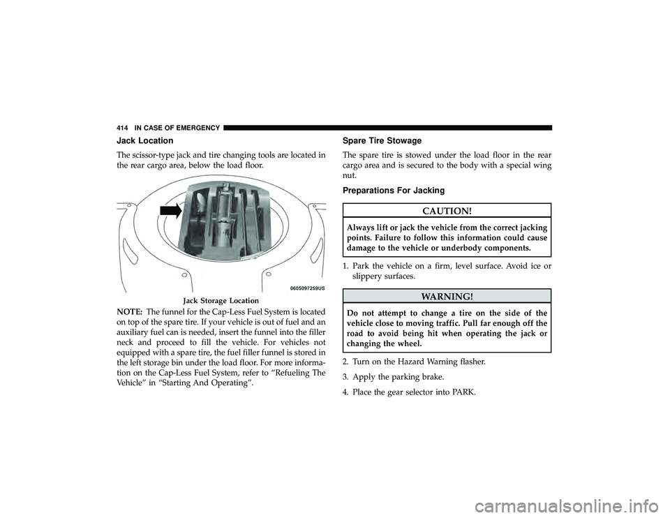
Jack Location
The scissor-type jack and tire changing tools are located in
the rear cargo area, below the load floor.
NOTE:The funnel for the Cap-Less Fuel System is located
on top of the spare tire. If your vehicle is out of fuel and an
auxiliary fuel can is needed, insert the funnel into the filler
neck and proceed to fill the vehicle. For vehicles not
equipped with a spare tire, the fuel filler funnel is stored in
the left storage bin under the load floor. For more informa-
tion on the Cap-Less Fuel System, refer to “Refueling The
Vehicle” in “Starting And Operating”.
Spare Tire Stowage
The spare tire is stowed under the load floor in the rear
cargo area and is secured to the body with a special wing
nut.
Preparations For Jacking
Page 417 of 626
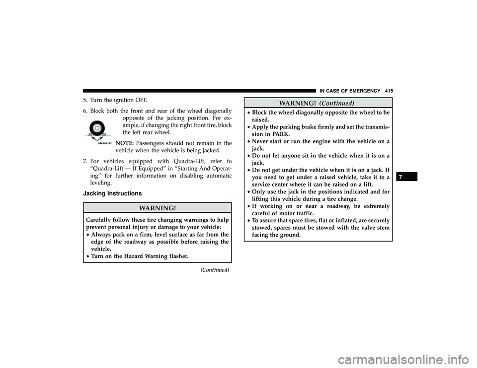
5. Turn the ignition OFF.
6. Block both the front and rear of the wheel diagonallyopposite of the jacking position. For ex-
ample, if changing the right front tire, block
the left rear wheel.
NOTE: Passengers should not remain in the
vehicle when the vehicle is being jacked.
7. For vehicles equipped with Quadra-Lift, refer to “Quadra-Lift — If Equipped” in “Starting And Operat-
ing” for further information on disabling automatic
leveling.
Jacking Instructions
7
IN CASE OF EMERGENCY 415
Page 418 of 626
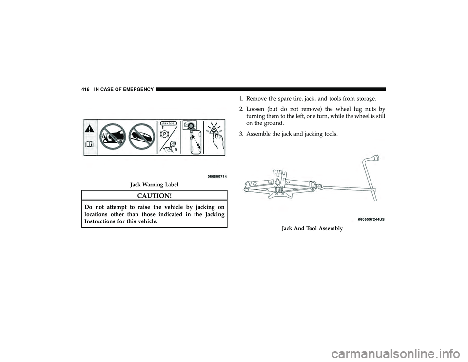
CAUTION!
Do not attempt to raise the vehicle by jacking on
locations other than those indicated in the Jacking
Instructions for this vehicle.1. Remove the spare tire, jack, and tools from storage.
2. Loosen (but do not remove) the wheel lug nuts by
turning them to the left, one turn, while the wheel is still
on the ground.
3. Assemble the jack and jacking tools.
Jack And Tool Assembly
416 IN CASE OF EMERGENCY
Page 419 of 626
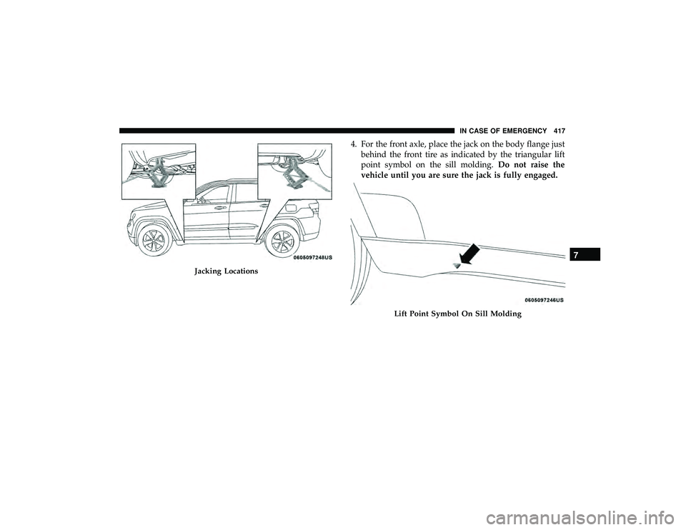
4. For the front axle, place the jack on the body flange justbehind the front tire as indicated by the triangular lift
point symbol on the sill molding. Do not raise the
vehicle until you are sure the jack is fully engaged.
Jacking Locations
Lift Point Symbol On Sill Molding
7
IN CASE OF EMERGENCY 417
Page 420 of 626
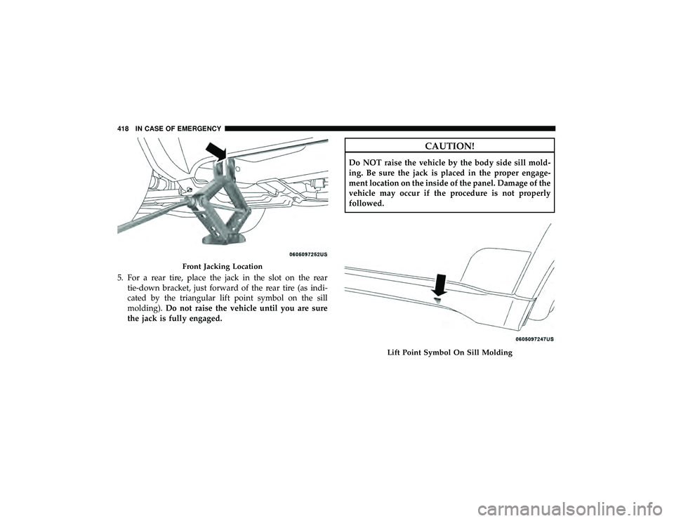
5. For a rear tire, place the jack in the slot on the reartie-down bracket, just forward of the rear tire (as indi-
cated by the triangular lift point symbol on the sill
molding). Do not raise the vehicle until you are sure
the jack is fully engaged.
CAUTION!
Do NOT raise the vehicle by the body side sill mold-
ing. Be sure the jack is placed in the proper engage-
ment location on the inside of the panel. Damage of the
vehicle may occur if the procedure is not properly
followed.
Front Jacking Location
Lift Point Symbol On Sill Molding
418 IN CASE OF EMERGENCY
Trending: center console, child seat, tire size, spare tire, odometer, clutch, oil capacities
