engine JEEP LIBERTY 2002 KJ / 1.G Workshop Manual
[x] Cancel search | Manufacturer: JEEP, Model Year: 2002, Model line: LIBERTY, Model: JEEP LIBERTY 2002 KJ / 1.GPages: 1803, PDF Size: 62.3 MB
Page 1389 of 1803
(3) Remove 4 fuel pump module access plate nuts
(Fig. 3).
(4) While applying heat from a heat gun, carefully
pry up fuel pump module access plate. Take care not
to bend plate.
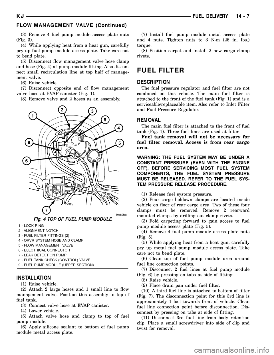
(5) Disconnect flow management valve hose clamp
and hose (Fig. 4) at pump module fitting. Also discon-
nect small recirculation line at top half of manage-
ment valve.
(6) Raise vehicle.
(7) Disconnect opposite end of flow management
valve hose at EVAP canister (Fig. 1).
(8) Remove valve and 2 hoses as an assembly.
INSTALLATION
(1) Raise vehicle.
(2) Attach 2 large hoses and 1 small line to flow
management valve. Position this assembly to top of
fuel tank.
(3) Connect valve hose at EVAP canister.
(4) Lower vehicle.
(5) Attach valve hose and clamp to top of fuel
pump module.
(6) Apply silicone sealant to bottom of fuel pump
module metal access plate.(7) Install fuel pump module metal access plate
and 4 nuts. Tighten nuts to 3 N´m (26 in. lbs.)
torque.
(8) Position carpet and install 2 new cargo clamp
rivets.
FUEL FILTER
DESCRIPTION
The fuel pressure regulator and fuel filter are not
combined on this vehicle. The main fuel filter is
attached to the front of the fuel tank (Fig. 1) and is a
serviceable/replaceable item. Also refer to Inlet Filter
and Fuel Pressure Regulator.
REMOVAL
The main fuel filter is attached to the front of fuel
tank (Fig. 1). Three fuel lines are used at filter.
Fuel tank removal will not be necessary for
fuel filter removal. Access is from rear cargo
area.
WARNING: THE FUEL SYSTEM MAY BE UNDER A
CONSTANT PRESSURE (EVEN WITH THE ENGINE
OFF). BEFORE SERVICING MOST FUEL SYSTEM
COMPONENTS, THE FUEL SYSTEM PRESSURE
MUST BE RELEASED. REFER TO THE FUEL SYS-
TEM PRESSURE RELEASE PROCEDURE.
(1) Release fuel system pressure.
(2) Four cargo holdown clamps are located inside
vehicle on floor of rear cargo area. Two of these four
clamps must be removed. Remove 2 rearward
mounted clamps by drilling out clamp rivets.
(3) Fold carpeting forward to gain access to fuel
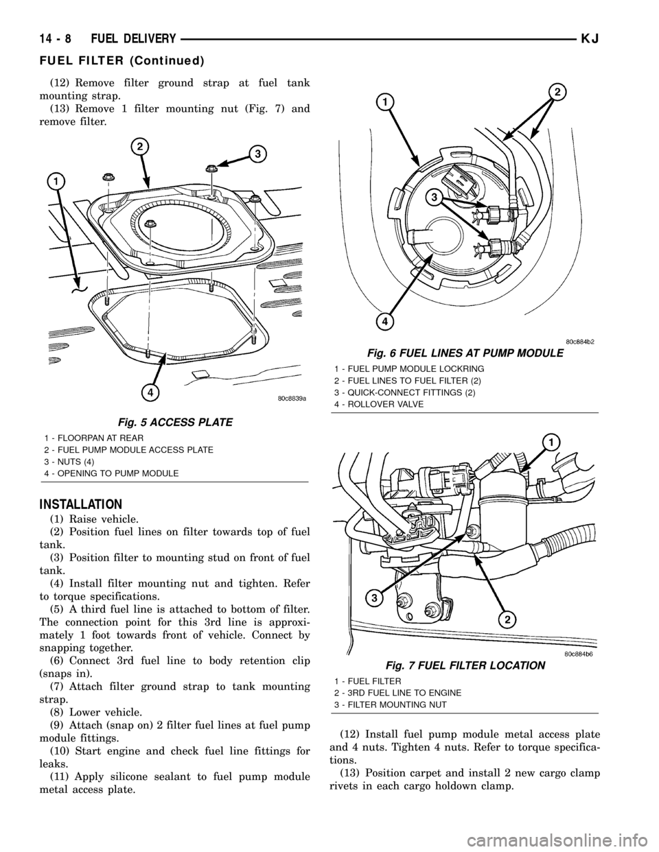
pump module access plate (Fig. 5).
(4) Remove 4 fuel pump module access plate nuts
(Fig. 5).
(5) While applying heat from a heat gun, carefully
pry up metal fuel pump module access plate. Take
care not to bend plate.
(6) Clean top of fuel pump module area around
fuel line connection points.
(7) Disconnect 2 fuel lines at fuel pump module
(Fig. 6) by pressing on tabs at side of fitting.
(8) Raise vehicle.
(9) Place drain pan under fuel filter.
(10) A third fuel line is attached to bottom of filter
(Fig. 7). The disconnection point for this 3rd line is
approximately 1 foot towards front of vehicle. Clean
fuel line connection point before disconnection. Dis-
connect by pressing on tabs at side of fitting.
(11) Disconnect 3rd fuel line from body retention
clip. Place a small screwdriver into side of clip and
twist for removal.
Fig. 4 TOP OF FUEL PUMP MODULE
1 - LOCK RING
2 - ALIGNMENT NOTCH
3 - FUEL FILTER FITTINGS (2)
4 - ORVR SYSTEM HOSE AND CLAMP
5 - FLOW MANAGEMENT VALVE
6 - ELECTRICAL CONNECTOR
7 - LEAK DETECTION PUMP
8 - FUEL TANK CHECK (CONTROL) VALVE
9 - FUEL PUMP MODULE (UPPER SECTION)
KJFUEL DELIVERY 14 - 7
FLOW MANAGEMENT VALVE (Continued)
Page 1390 of 1803
(12) Remove filter ground strap at fuel tank
mounting strap.
(13) Remove 1 filter mounting nut (Fig. 7) and
remove filter.
INSTALLATION
(1) Raise vehicle.
(2) Position fuel lines on filter towards top of fuel
tank.
(3) Position filter to mounting stud on front of fuel
tank.
(4) Install filter mounting nut and tighten. Refer
to torque specifications.
(5) A third fuel line is attached to bottom of filter.
The connection point for this 3rd line is approxi-
mately 1 foot towards front of vehicle. Connect by
snapping together.
(6) Connect 3rd fuel line to body retention clip
(snaps in).
(7) Attach filter ground strap to tank mounting
strap.
(8) Lower vehicle.
(9) Attach (snap on) 2 filter fuel lines at fuel pump
module fittings.
(10) Start engine and check fuel line fittings for
leaks.
(11) Apply silicone sealant to fuel pump module
metal access plate.(12) Install fuel pump module metal access plate
and 4 nuts. Tighten 4 nuts. Refer to torque specifica-
tions.
(13) Position carpet and install 2 new cargo clamp
rivets in each cargo holdown clamp.
Fig. 5 ACCESS PLATE
1 - FLOORPAN AT REAR
2 - FUEL PUMP MODULE ACCESS PLATE
3 - NUTS (4)
4 - OPENING TO PUMP MODULE
Fig. 6 FUEL LINES AT PUMP MODULE
1 - FUEL PUMP MODULE LOCKRING
2 - FUEL LINES TO FUEL FILTER (2)
3 - QUICK-CONNECT FITTINGS (2)
4 - ROLLOVER VALVE
Fig. 7 FUEL FILTER LOCATION
1 - FUEL FILTER
2 - 3RD FUEL LINE TO ENGINE
3 - FILTER MOUNTING NUT
14 - 8 FUEL DELIVERYKJ
FUEL FILTER (Continued)
Page 1392 of 1803
INSTALLATION
(1) Connect necessary wiring into electrical con-
nectors. Connect 4±wire connector to upper section of
pump module.
(2) Position sending unit to pump module. Slide
and snap into place.
(3) Install lower section of fuel pump module.
Refer to Fuel Pump Module Removal/Installation.
FUEL LINES
DESCRIPTION
Also refer to Quick-Connect Fittings.
WARNING: THE FUEL SYSTEM MAY BE UNDER A
CONSTANT PRESSURE (EVEN WITH THE ENGINE
OFF). BEFORE SERVICING ANY FUEL SYSTEM
HOSES, FITTINGS, LINES, OR MOST COMPO-
NENTS, FUEL SYSTEM PRESSURE MUST BE
RELEASED. REFER TO THE FUEL SYSTEM PRES-
SURE RELEASE PROCEDURE.
The lines/tubes/hoses used on fuel injected vehicles
are of a special construction. This is due to the
higher fuel pressures and the possibility of contami-nated fuel in this system. If it is necessary to replace
these lines/tubes/hoses, only those marked EFM/EFI
may be used.
If equipped:The hose clamps used to secure rub-
ber hoses on fuel injected vehicles are of a special
rolled edge construction. This construction is used to
prevent the edge of the clamp from cutting into the
hose. Only these rolled edge type clamps may be
used in this system. All other types of clamps may
cut into the hoses and cause high-pressure fuel leaks.
Use new original equipment type hose clamps.
QUICK CONNECT FITTING
DESCRIPTION
Different types of quick-connect fittings are used to
attach various fuel system components, lines and
tubes. These are: a single-tab type, a two-tab type or
a plastic retainer ring type. Some are equipped with
safety latch clips. Some may require the use of a spe-
cial tool for disconnection and removal. Refer to
Quick-Connect Fittings Removal/Installation for more
information.
CAUTION: The interior components (o-rings, clips)
of quick-connect fittings are not serviced sepa-
rately, but new plastic spacers are available for
some types. If service parts are not available, do
not attempt to repair the damaged fitting or fuel line
(tube). If repair is necessary, replace the complete
fuel line (tube) assembly.
STANDARD PROCEDURE - QUICK-CONNECT
FITTINGS
Also refer to Fuel Tubes/Lines/Hoses and Clamps.
Different types of quick-connect fittings are used to
attach various fuel system components, lines and
tubes. These are: a single-tab type, a two-tab type or
a plastic retainer ring type. Safety latch clips are
used on certain components/lines. Certain fittings
may require use of a special tool for disconnection.
DISCONNECTING
WARNING: THE FUEL SYSTEM IS UNDER A CON-
STANT PRESSURE (EVEN WITH ENGINE OFF).
BEFORE SERVICING ANY FUEL SYSTEM HOSE,
FITTING OR LINE, FUEL SYSTEM PRESSURE MUST
BE RELEASED. REFER TO FUEL SYSTEM PRES-
SURE RELEASE PROCEDURE.
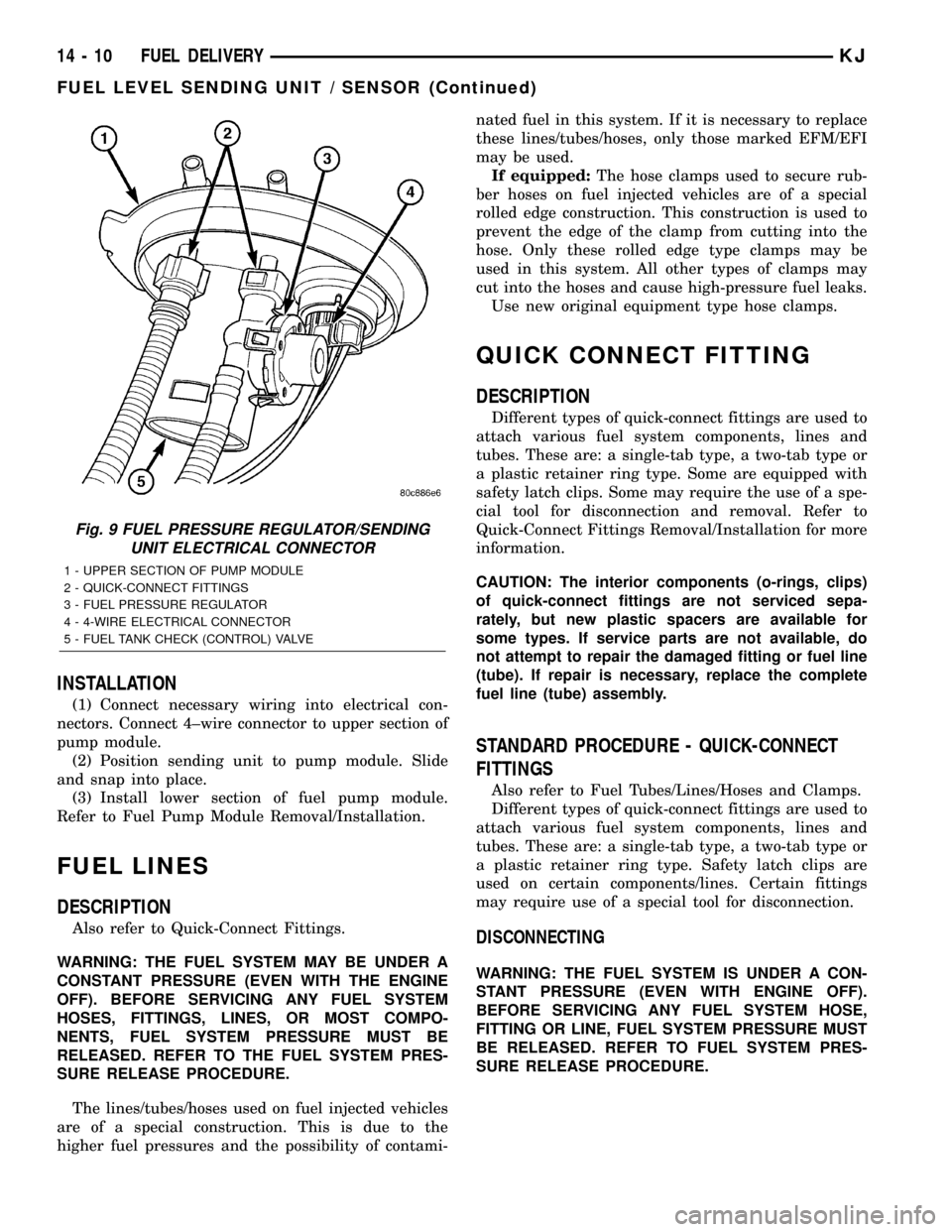
Fig. 9 FUEL PRESSURE REGULATOR/SENDING
UNIT ELECTRICAL CONNECTOR
1 - UPPER SECTION OF PUMP MODULE
2 - QUICK-CONNECT FITTINGS
3 - FUEL PRESSURE REGULATOR
4 - 4-WIRE ELECTRICAL CONNECTOR
5 - FUEL TANK CHECK (CONTROL) VALVE
14 - 10 FUEL DELIVERYKJ
FUEL LEVEL SENDING UNIT / SENSOR (Continued)
Page 1395 of 1803
(b) After disconnection, plastic retainer ring will
remain with quick-connect fitting connector body.
(c) Inspect fitting connector body, plastic retainer
ring and fuel system component for damage.
Replace as necessary.
(8)Latch Clips:Depending on vehicle model and
engine, 2 different types of safety latch clips are used
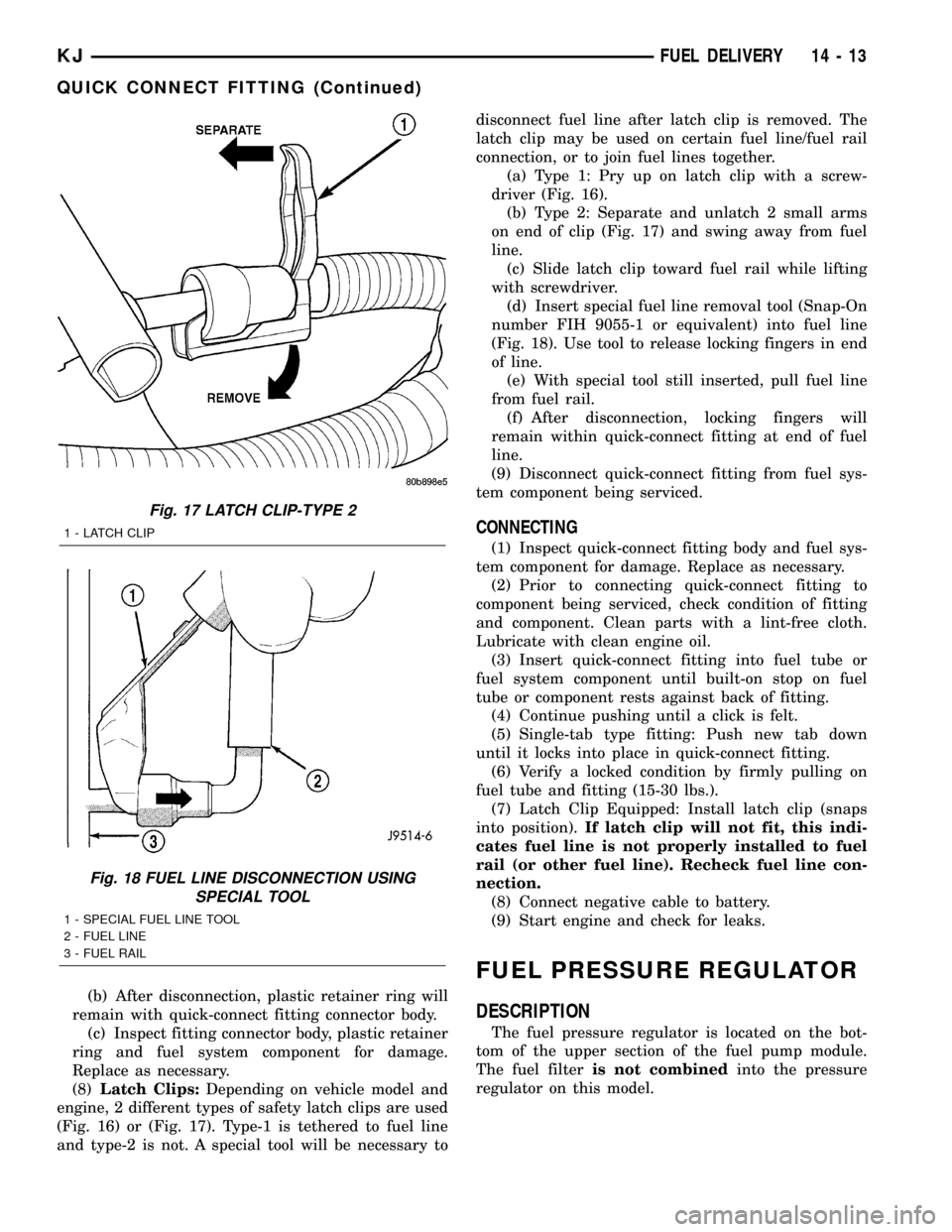
(Fig. 16) or (Fig. 17). Type-1 is tethered to fuel line
and type-2 is not. A special tool will be necessary todisconnect fuel line after latch clip is removed. The
latch clip may be used on certain fuel line/fuel rail
connection, or to join fuel lines together.
(a) Type 1: Pry up on latch clip with a screw-
driver (Fig. 16).
(b) Type 2: Separate and unlatch 2 small arms
on end of clip (Fig. 17) and swing away from fuel
line.
(c) Slide latch clip toward fuel rail while lifting
with screwdriver.
(d) Insert special fuel line removal tool (Snap-On
number FIH 9055-1 or equivalent) into fuel line
(Fig. 18). Use tool to release locking fingers in end
of line.
(e) With special tool still inserted, pull fuel line
from fuel rail.
(f) After disconnection, locking fingers will
remain within quick-connect fitting at end of fuel
line.
(9) Disconnect quick-connect fitting from fuel sys-
tem component being serviced.
CONNECTING
(1) Inspect quick-connect fitting body and fuel sys-
tem component for damage. Replace as necessary.
(2) Prior to connecting quick-connect fitting to
component being serviced, check condition of fitting
and component. Clean parts with a lint-free cloth.
Lubricate with clean engine oil.
(3) Insert quick-connect fitting into fuel tube or
fuel system component until built-on stop on fuel
tube or component rests against back of fitting.
(4) Continue pushing until a click is felt.
(5) Single-tab type fitting: Push new tab down
until it locks into place in quick-connect fitting.
(6) Verify a locked condition by firmly pulling on
fuel tube and fitting (15-30 lbs.).
(7) Latch Clip Equipped: Install latch clip (snaps
into position).If latch clip will not fit, this indi-
cates fuel line is not properly installed to fuel
rail (or other fuel line). Recheck fuel line con-
nection.
(8) Connect negative cable to battery.
(9) Start engine and check for leaks.
FUEL PRESSURE REGULATOR
DESCRIPTION
The fuel pressure regulator is located on the bot-
tom of the upper section of the fuel pump module.
The fuel filteris not combinedinto the pressure
regulator on this model.
Fig. 17 LATCH CLIP-TYPE 2
1 - LATCH CLIP
Fig. 18 FUEL LINE DISCONNECTION USING
SPECIAL TOOL
1 - SPECIAL FUEL LINE TOOL
2 - FUEL LINE
3 - FUEL RAIL
KJFUEL DELIVERY 14 - 13
QUICK CONNECT FITTING (Continued)
Page 1396 of 1803
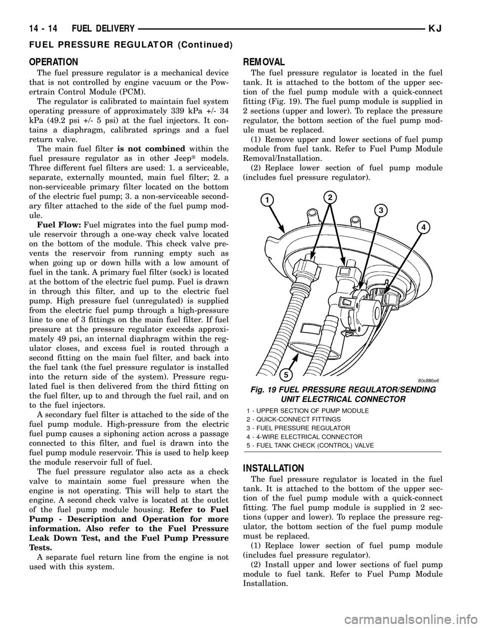
OPERATION
The fuel pressure regulator is a mechanical device
that is not controlled by engine vacuum or the Pow-
ertrain Control Module (PCM).
The regulator is calibrated to maintain fuel system
operating pressure of approximately 339 kPa +/- 34
kPa (49.2 psi +/- 5 psi) at the fuel injectors. It con-
tains a diaphragm, calibrated springs and a fuel
return valve.
The main fuel filteris not combinedwithin the
fuel pressure regulator as in other Jeeptmodels.
Three different fuel filters are used: 1. a serviceable,
separate, externally mounted, main fuel filter; 2. a
non-serviceable primary filter located on the bottom
of the electric fuel pump; 3. a non-serviceable second-
ary filter attached to the side of the fuel pump mod-
ule.
Fuel Flow:Fuel migrates into the fuel pump mod-
ule reservoir through a one-way check valve located
on the bottom of the module. This check valve pre-
vents the reservoir from running empty such as
when going up or down hills with a low amount of
fuel in the tank. A primary fuel filter (sock) is located
at the bottom of the electric fuel pump. Fuel is drawn
in through this filter, and up to the electric fuel
pump. High pressure fuel (unregulated) is supplied
from the electric fuel pump through a high-pressure
line to one of 3 fittings on the main fuel filter. If fuel
pressure at the pressure regulator exceeds approxi-
mately 49 psi, an internal diaphragm within the reg-
ulator closes, and excess fuel is routed through a
second fitting on the main fuel filter, and back into
the fuel tank (the fuel pressure regulator is installed
into the return side of the system). Pressure regu-
lated fuel is then delivered from the third fitting on
the fuel filter, up to and through the fuel rail, and on
to the fuel injectors.
A secondary fuel filter is attached to the side of the
fuel pump module. High-pressure from the electric
fuel pump causes a siphoning action across a passage
connected to this filter, and fuel is drawn into the
fuel pump module reservoir. This is used to help keep
the module reservoir full of fuel.
The fuel pressure regulator also acts as a check
valve to maintain some fuel pressure when the
engine is not operating. This will help to start the
engine. A second check valve is located at the outlet
of the fuel pump module housing.Refer to Fuel
Pump - Description and Operation for more
information. Also refer to the Fuel Pressure
Leak Down Test, and the Fuel Pump Pressure
Tests.
A separate fuel return line from the engine is not
used with this system.
REMOVAL
The fuel pressure regulator is located in the fuel
tank. It is attached to the bottom of the upper sec-
tion of the fuel pump module with a quick-connect
fitting (Fig. 19). The fuel pump module is supplied in
2 sections (upper and lower). To replace the pressure
regulator, the bottom section of the fuel pump mod-
ule must be replaced.
(1) Remove upper and lower sections of fuel pump
module from fuel tank. Refer to Fuel Pump Module
Removal/Installation.
(2) Replace lower section of fuel pump module
(includes fuel pressure regulator).
INSTALLATION
The fuel pressure regulator is located in the fuel
tank. It is attached to the bottom of the upper sec-
tion of the fuel pump module with a quick-connect
fitting. The fuel pump module is supplied in 2 sec-
tions (upper and lower). To replace the pressure reg-
ulator, the bottom section of the fuel pump module
must be replaced.
(1) Replace lower section of fuel pump module
(includes fuel pressure regulator).
(2) Install upper and lower sections of fuel pump
module to fuel tank. Refer to Fuel Pump Module
Installation.
Fig. 19 FUEL PRESSURE REGULATOR/SENDING
UNIT ELECTRICAL CONNECTOR
1 - UPPER SECTION OF PUMP MODULE
2 - QUICK-CONNECT FITTINGS
3 - FUEL PRESSURE REGULATOR
4 - 4-WIRE ELECTRICAL CONNECTOR
5 - FUEL TANK CHECK (CONTROL) VALVE
14 - 14 FUEL DELIVERYKJ
FUEL PRESSURE REGULATOR (Continued)
Page 1397 of 1803
FUEL PUMP
DESCRIPTION
The electric fuel pump is located inside of the fuel
pump module. A 12 volt, permanent magnet, electric
motor powers the fuel pump. The electric fuel pump
is not a separate, serviceable component.
OPERATION
Voltage to operate the electric pump is supplied
through the fuel pump relay.
Fuel is drawn in through a filter at the bottom of
the module and pushed through the electric motor
gearset to the pump outlet.
Check Valve Operation:The bottom section of
the fuel pump module contains a one-way check
valve to prevent fuel flow back into the tank and to
maintain fuel supply line pressure (engine warm)
when pump is not operational. It is also used to keep
the fuel supply line full of gasoline when pump is not
operational. After the vehicle has cooled down, fuel
pressure may drop to 0 psi (cold fluid contracts), but
liquid gasoline will remain in fuel supply line
between the check valve and fuel injectors.Fuel
pressure that has dropped to 0 psi on a cooled
down vehicle (engine off) is a normal condition.
Refer to the Fuel Pressure Leak Down Test for more
information.
The electric fuel pump is not a separate, service-
able component.
DIAGNOSIS AND TESTING
DIAGNOSIS AND TESTING - FUEL PUMP
CAPACITY TEST
Before performing this test, verify fuel pump
pressure. Refer to Fuel Pump Pressure Test.
Use this test in conjunction with the Fuel Pres-
sure Leak Down Test.
(1) Release fuel system pressure. Refer to Fuel
Pressure Release Procedure.
(2) Disconnect fuel supply line at fuel rail. Refer to
Quick-Connect Fittings. Some engines may require
air cleaner housing removal before line disconnection.
(3) Obtain correct Fuel Line Pressure Test Adapter
Tool Hose. Tool number 6539 is used for 5/16º fuel
lines and tool number 6631 is used for 3/8º fuel lines.
(4) Connect correct Fuel Line Pressure Test
Adapter Tool Hose into disconnected fuel supply line.
Insert other end of Adaptor Tool Hose into a gradu-
ated container.
(5) Remove fuel fill cap.(6) To activate fuel pump and pressurize system,
obtain DRBtscan tool and actuate ASD Fuel System
Test.
(7) A good fuel pump will deliver at least 1/10 liter
of fuel in 7 seconds. Do not operate fuel pump for
longer than 7 seconds with fuel line disconnected as
fuel pump module reservoir may run empty.
(a) If capacity is lower than specification, but
fuel pump can be heard operating through fuel fill
cap opening, check for a kinked/damaged fuel sup-
ply line somewhere between fuel rail and fuel
pump module.
(b) If line is not kinked/damaged, and fuel pres-
sure is OK, but capacity is low, replace fuel filter.
Refer to Fuel Filter Removal/Installation for addi-
tional information.
(c) If both fuel pressure and capacity are low,
replace bottom section of fuel pump module. Refer
to Fuel Pump Module Removal/Installation.
DIAGNOSIS AND TESTING - FUEL PUMP
PRESSURE TEST
Use this test in conjunction with the Fuel Pump
Capacity Test, Fuel Pressure Leak Down Test and
Fuel Pump Amperage Test found elsewhere in this
group.
Check Valve Operation:The bottom section of
the fuel pump module contains a one-way check
valve to prevent fuel flow back into the tank and to
maintain fuel supply line pressure (engine warm)
when pump is not operational. It is also used to keep
the fuel supply line full of gasoline when pump is not
operational. After the vehicle has cooled down, fuel
pressure may drop to 0 psi (cold fluid contracts), but
liquid gasoline will remain in fuel supply line
between the check valve and fuel injectors.Fuel
pressure that has dropped to 0 psi on a cooled
down vehicle (engine off) is a normal condition.
When the electric fuel pump is activated, fuel pres-
sure shouldimmediately(1±2 seconds) rise to spec-
ification.
The fuel system is equipped with a separate fuel
pump module mounted, fuel pressure regulator. The
fuel filter is remotely mounted. The fuel pressure
regulator is not controlled by engine vacuum.
WARNING: THE FUEL SYSTEM IS UNDER CON-
STANT FUEL PRESSURE EVEN WITH THE ENGINE
OFF. BEFORE DISCONNECTING FUEL LINE AT
FUEL RAIL, THIS PRESSURE MUST BE RELEASED.
REFER TO THE FUEL SYSTEM PRESSURE
RELEASE PROCEDURE.
KJFUEL DELIVERY 14 - 15
Page 1398 of 1803
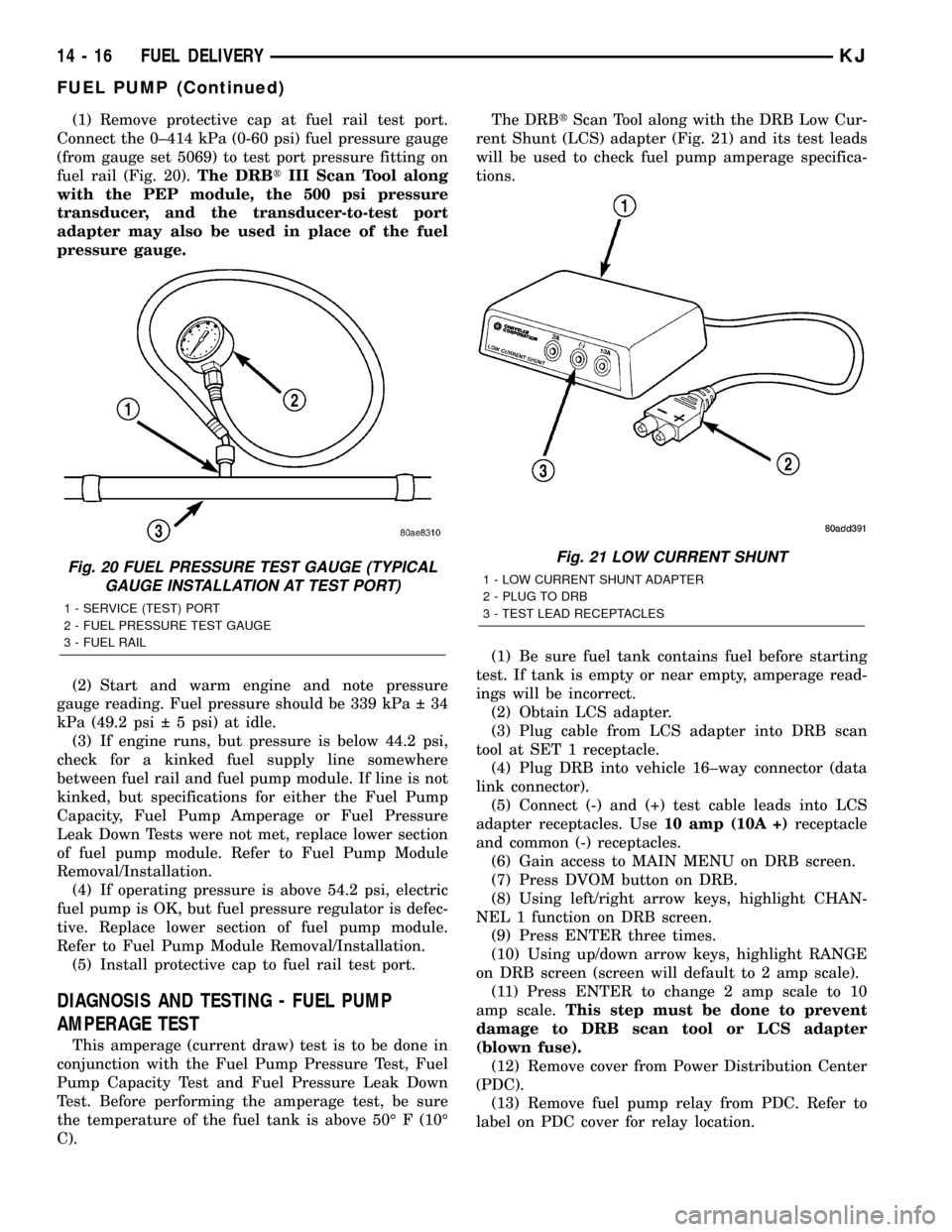
(1) Remove protective cap at fuel rail test port.
Connect the 0±414 kPa (0-60 psi) fuel pressure gauge
(from gauge set 5069) to test port pressure fitting on
fuel rail (Fig. 20).The DRBtIII Scan Tool along
with the PEP module, the 500 psi pressure
transducer, and the transducer-to-test port
adapter may also be used in place of the fuel
pressure gauge.
(2) Start and warm engine and note pressure
gauge reading. Fuel pressure should be 339 kPa 34
kPa (49.2 psi 5 psi) at idle.
(3) If engine runs, but pressure is below 44.2 psi,
check for a kinked fuel supply line somewhere
between fuel rail and fuel pump module. If line is not
kinked, but specifications for either the Fuel Pump
Capacity, Fuel Pump Amperage or Fuel Pressure
Leak Down Tests were not met, replace lower section
of fuel pump module. Refer to Fuel Pump Module
Removal/Installation.
(4) If operating pressure is above 54.2 psi, electric
fuel pump is OK, but fuel pressure regulator is defec-
tive. Replace lower section of fuel pump module.
Refer to Fuel Pump Module Removal/Installation.
(5) Install protective cap to fuel rail test port.
DIAGNOSIS AND TESTING - FUEL PUMP
AMPERAGE TEST
This amperage (current draw) test is to be done in
conjunction with the Fuel Pump Pressure Test, Fuel
Pump Capacity Test and Fuel Pressure Leak Down
Test. Before performing the amperage test, be sure
the temperature of the fuel tank is above 50É F (10É
C).The DRBtScan Tool along with the DRB Low Cur-
rent Shunt (LCS) adapter (Fig. 21) and its test leads
will be used to check fuel pump amperage specifica-
tions.
(1) Be sure fuel tank contains fuel before starting
test. If tank is empty or near empty, amperage read-
ings will be incorrect.
(2) Obtain LCS adapter.
(3) Plug cable from LCS adapter into DRB scan
tool at SET 1 receptacle.
(4) Plug DRB into vehicle 16±way connector (data
link connector).
(5) Connect (-) and (+) test cable leads into LCS
adapter receptacles. Use10 amp (10A +)receptacle
and common (-) receptacles.
(6) Gain access to MAIN MENU on DRB screen.
(7) Press DVOM button on DRB.
(8) Using left/right arrow keys, highlight CHAN-
NEL 1 function on DRB screen.
(9) Press ENTER three times.
(10) Using up/down arrow keys, highlight RANGE
on DRB screen (screen will default to 2 amp scale).
(11) Press ENTER to change 2 amp scale to 10
amp scale.This step must be done to prevent
damage to DRB scan tool or LCS adapter
(blown fuse).
(12) Remove cover from Power Distribution Center
(PDC).
(13) Remove fuel pump relay from PDC. Refer to
label on PDC cover for relay location.
Fig. 20 FUEL PRESSURE TEST GAUGE (TYPICAL
GAUGE INSTALLATION AT TEST PORT)
1 - SERVICE (TEST) PORT
2 - FUEL PRESSURE TEST GAUGE
3 - FUEL RAIL
Fig. 21 LOW CURRENT SHUNT
1 - LOW CURRENT SHUNT ADAPTER
2 - PLUG TO DRB
3 - TEST LEAD RECEPTACLES
14 - 16 FUEL DELIVERYKJ
FUEL PUMP (Continued)
Page 1399 of 1803
WARNING: BEFORE PROCEEDING TO NEXT STEP,
NOTE THE FUEL PUMP WILL BE ACTIVATED AND
SYSTEM PRESSURE WILL BE PRESENT. THIS WILL
OCCUR AFTER CONNECTING TEST LEADS FROM
LCS ADAPTER INTO FUEL PUMP RELAY CAVITIES.
THE FUEL PUMP WILL OPERATE EVEN WITH IGNI-
TION KEY IN OFF POSITION. BEFORE ATTACHING
TEST LEADS, BE SURE ALL FUEL LINES AND
FUEL SYSTEM COMPONENTS ARE CONNECTED.
CAUTION: To prevent possible damage to the vehi-
cle electrical system and LCS adapter, the test
leads must be connected into relay cavities exactly
as shown in following steps.
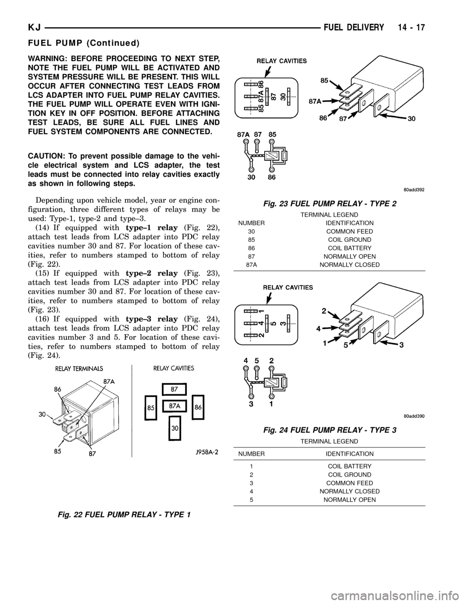
Depending upon vehicle model, year or engine con-
figuration, three different types of relays may be
used: Type-1, type-2 and type±3.
(14) If equipped withtype±1 relay(Fig. 22),
attach test leads from LCS adapter into PDC relay
cavities number 30 and 87. For location of these cav-
ities, refer to numbers stamped to bottom of relay
(Fig. 22).
(15) If equipped withtype±2 relay(Fig. 23),
attach test leads from LCS adapter into PDC relay
cavities number 30 and 87. For location of these cav-
ities, refer to numbers stamped to bottom of relay
(Fig. 23).
(16) If equipped withtype±3 relay(Fig. 24),
attach test leads from LCS adapter into PDC relay
cavities number 3 and 5. For location of these cavi-
ties, refer to numbers stamped to bottom of relay
(Fig. 24).
Fig. 22 FUEL PUMP RELAY - TYPE 1
Fig. 23 FUEL PUMP RELAY - TYPE 2
TERMINAL LEGEND
NUMBER IDENTIFICATION
30 COMMON FEED
85 COIL GROUND
86 COIL BATTERY
87 NORMALLY OPEN
87A NORMALLY CLOSED
Fig. 24 FUEL PUMP RELAY - TYPE 3
TERMINAL LEGEND
NUMBER IDENTIFICATION
1 COIL BATTERY
2 COIL GROUND
3 COMMON FEED
4 NORMALLY CLOSED
5 NORMALLY OPEN
KJFUEL DELIVERY 14 - 17
FUEL PUMP (Continued)
Page 1400 of 1803
(17) When LCS adapter test leads are attached
into relay cavities, fuel pumpwill be activated.
Determine fuel pump amperage on DRB screen.
Amperage should be below 10.0 amps. If amperage is
below 10.0 amps, and specifications for the Fuel
Pump Pressure, Fuel Pump Capacity and Fuel Pres-
sure Leak Down tests were met, the fuel pump mod-
ule is OK.
(18) If amperage is more than 10.0 amps, replace
fuel pump module assembly. The electric fuel pump
is not serviced separately.
(19) Disconnect test leads from relay cavities
immediately after testing.
FUEL PUMP MODULE
DESCRIPTION
The fuel pump module assembly is located in the
fuel tank (Fig. 1). The assembly is divided into 2±sec-
tions, upper and lower. The lower section is locked to
the bottom of the fuel tank. The complete assembly
contains the following components:
²A fuel pressure regulator
²A separate fuel pick-up, or inlet filter
²An electric fuel pump
²A lockring to retain upper section of pump mod-
ule to tank
²A rollover valve
²A vent fitting for ORVR system
²A soft gasket between tank flange and module
²A fuel gauge sending unit (fuel level sensor)
²Two fuel line connections (supply and return)
The fuel gauge sending unit may be serviced sepa-
rately. If the electrical fuel pump, primary inlet filter
or fuel pressure regulator require service, the lower
section of the fuel pump module must be replaced.
OPERATION
Refer to Fuel Pump, Inlet Filter, Fuel Pressure
Regulator and Fuel Gauge Sending Unit.
REMOVAL
The fuel pump module is divided into 2 sections,
upper and lower. To service the check (control) valve,
replace only the upper section. To service the fuel
gauge sending unit, remove the upper section. To ser-
vice the electric fuel pump, fuel pressure regulator or
primary inlet filter, remove both sections and replace
lower section.
Fuel tank removal will not be necessary for
fuel pump module removal. Access is from rear
cargo area.
(1) Four cargo holdown clamps are located inside
the vehicle on the floor of the rear cargo area.Remove the 2 rearward mounted clamps by drilling
out the clamp rivets.
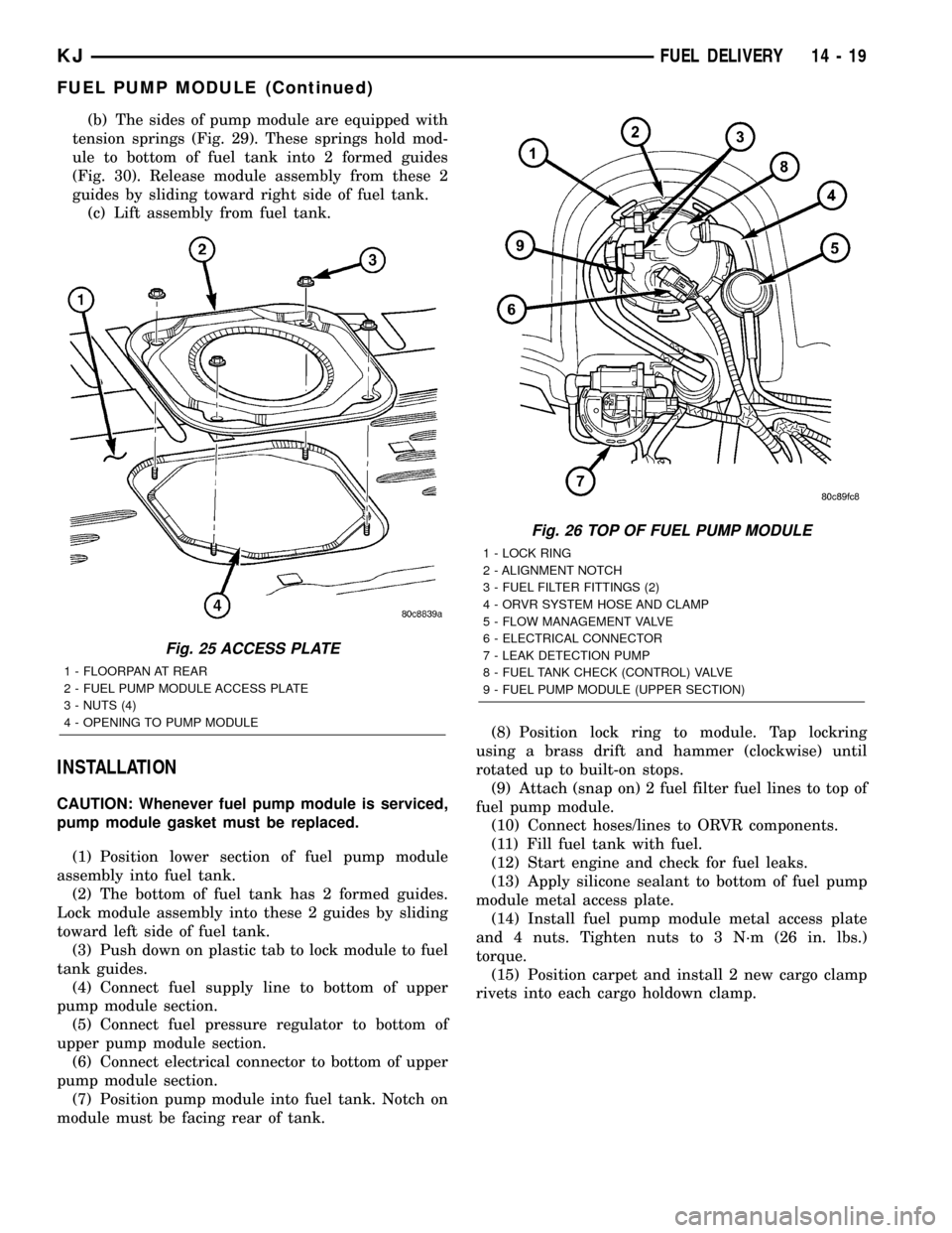
(2) Fold carpeting forward to gain access to fuel
pump module access plate (Fig. 25).
(3) Remove 4 fuel pump module access plate nuts
(Fig. 25).
(4) While applying heat from a heat gun, carefully
pry up fuel pump module access plate. Take care not
to bend plate.
(5) Thoroughly clean area around top of pump
module to prevent contaminants from entering fuel
tank or fuel lines.
WARNING: THE FUEL SYSTEM IS UNDER A CON-
STANT PRESSURE EVEN WITH ENGINE OFF.
BEFORE SERVICING THE FUEL PUMP MODULE,
FUEL SYSTEM PRESSURE MUST BE RELEASED.
(6) Release fuel system pressure. Refer to Fuel
System Pressure Release procedure.
(7) Disconnect 2 fuel lines at fuel pump module
(Fig. 26) by pressing on 2 buttons at sides of fitting.
(8) Disconnect electrical connector (Fig. 26) at top
of fuel pump module by sliding red colored tab first
to unlock, and push grey colored tab down for
removal.
(9) Disconnect ORVR hose clamp and hose (Fig.
26) at pump module fitting.
(10) Remove module lockring (Fig. 26) using a
brass drift and hammer (counter-clockwise).
(11) Carefully lift upper section of pump module
(Fig. 26) from fuel tank exposing connections(lift
upper section from tank very slowly until rub-
ber gasket can be retained. If not, gasket will
fall into fuel tank.)
(a) Disconnect electrical connector (Fig. 27) at
bottom of upper pump module section.
(b) Disconnect fuel pressure regulator (Fig. 27)
at bottom of upper pump module section. Press on
2 locking tabs.
(c) Disconnect fuel return line (Fig. 27) at bot-
tom of upper pump module section. Press on 2
locking tabs.
(d) Remove upper section of pump module (Fig.
28) from fuel tank.
(12) Using an approved gas holding tank, drain
fuel tank through pump module opening.If check
(control) valve, or, only upper section of pump
module is being serviced, tank draining is not
necessary. If any other fuel pump module com-
ponent is being serviced, the tank must be com-
pletely drained to the bottom.
(13) To remove lower section of pump module from
fuel tank:
(a) Using finger pressure, push on plastic
release tab (Fig. 29) while sliding lock tab upward.
14 - 18 FUEL DELIVERYKJ
FUEL PUMP (Continued)
Page 1401 of 1803
(b) The sides of pump module are equipped with
tension springs (Fig. 29). These springs hold mod-
ule to bottom of fuel tank into 2 formed guides
(Fig. 30). Release module assembly from these 2
guides by sliding toward right side of fuel tank.
(c) Lift assembly from fuel tank.
INSTALLATION
CAUTION: Whenever fuel pump module is serviced,
pump module gasket must be replaced.
(1) Position lower section of fuel pump module
assembly into fuel tank.
(2) The bottom of fuel tank has 2 formed guides.
Lock module assembly into these 2 guides by sliding
toward left side of fuel tank.
(3) Push down on plastic tab to lock module to fuel
tank guides.
(4) Connect fuel supply line to bottom of upper
pump module section.
(5) Connect fuel pressure regulator to bottom of
upper pump module section.
(6) Connect electrical connector to bottom of upper
pump module section.
(7) Position pump module into fuel tank. Notch on
module must be facing rear of tank.(8) Position lock ring to module. Tap lockring
using a brass drift and hammer (clockwise) until
rotated up to built-on stops.
(9) Attach (snap on) 2 fuel filter fuel lines to top of
fuel pump module.
(10) Connect hoses/lines to ORVR components.
(11) Fill fuel tank with fuel.
(12) Start engine and check for fuel leaks.
(13) Apply silicone sealant to bottom of fuel pump
module metal access plate.
(14) Install fuel pump module metal access plate
and 4 nuts. Tighten nuts to 3 N´m (26 in. lbs.)
torque.
(15) Position carpet and install 2 new cargo clamp
rivets into each cargo holdown clamp.
Fig. 25 ACCESS PLATE
1 - FLOORPAN AT REAR
2 - FUEL PUMP MODULE ACCESS PLATE
3 - NUTS (4)
4 - OPENING TO PUMP MODULE
Fig. 26 TOP OF FUEL PUMP MODULE
1 - LOCK RING
2 - ALIGNMENT NOTCH
3 - FUEL FILTER FITTINGS (2)
4 - ORVR SYSTEM HOSE AND CLAMP
5 - FLOW MANAGEMENT VALVE
6 - ELECTRICAL CONNECTOR
7 - LEAK DETECTION PUMP
8 - FUEL TANK CHECK (CONTROL) VALVE
9 - FUEL PUMP MODULE (UPPER SECTION)
KJFUEL DELIVERY 14 - 19
FUEL PUMP MODULE (Continued)