steering wheel JEEP RENEGADE 2015 1.G User Guide
[x] Cancel search | Manufacturer: JEEP, Model Year: 2015, Model line: RENEGADE, Model: JEEP RENEGADE 2015 1.GPages: 220, PDF Size: 34.11 MB
Page 3 of 220
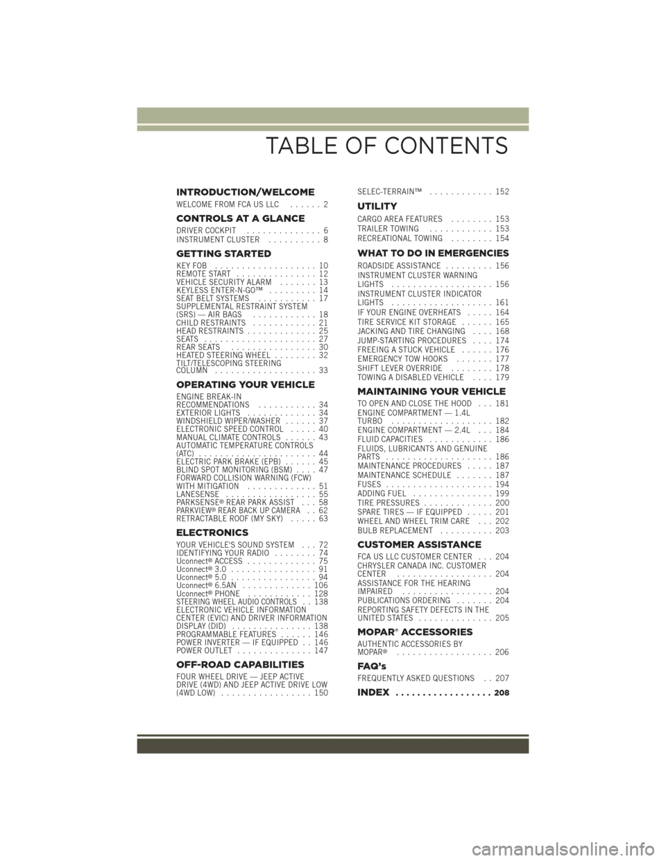
INTRODUCTION/WELCOME
WELCOME FROM FCA US LLC...... 2
CONTROLS AT A GLANCE
DRIVER COCKPIT.............. 6INSTRUMENT CLUSTER.......... 8
GETTING STARTED
KEY FOB . . . . . . . . . . . . . . . . . . . 10REMOTE START............... 12VEHICLE SECURITY ALARM....... 13KEYLESS ENTER-N-GO™......... 14SEAT BELT SYSTEMS........... 17SUPPLEMENTAL RESTRAINT SYSTEM(SRS) — AIR BAGS............ 18CHILD RESTRAINTS............ 21HEAD RESTRAINTS............. 25SEATS . . . . . . . . . . . . . . . . . . . . . 27REAR SEATS................ 30HEATED STEERING WHEEL........ 32TILT/TELESCOPING STEERINGCOLUMN................... 33
OPERATING YOUR VEHICLE
ENGINE BREAK-INRECOMMENDATIONS........... 34EXTERIOR LIGHTS............. 34WINDSHIELD WIPER/WASHER...... 37ELECTRONIC SPEED CONTROL..... 40MANUAL CLIMATE CONTROLS...... 43AUTOMATIC TEMPERATURE CONTROLS(ATC) . . . . . . . . . . . . . . . . . . . . . . 44ELECTRIC PARK BRAKE (EPB)...... 45BLIND SPOT MONITORING (BSM).... 47FORWARD COLLISION WARNING (FCW)WITH MITIGATION . . . . . . . . . . . . . 51LANESENSE................. 55PA R K S E N S E®REAR PARK ASSIST . . . 58PARKVIEW®REAR BACK UP CAMERA.. 62RETRACTABLE ROOF (MY SKY)..... 63
ELECTRONICS
YOUR VEHICLE'S SOUND SYSTEM . . . 72IDENTIFYING YOUR RADIO........ 74Uconnect®ACCESS............. 75Uconnect®3.0 . . . . . . . . . . . . . . . . 91Uconnect®5.0 . . . . . . . . . . . . . . . . 94Uconnect®6.5AN . . . . . . . . . . . . . 106Uconnect®PHONE............ 128STEERING WHEEL AUDIO CONTROLS.. 138ELECTRONIC VEHICLE INFORMATIONCENTER (EVIC) AND DRIVER INFORMATIONDISPLAY (DID)............... 138PROGRAMMABLE FEATURES...... 146POWER INVERTER — IF EQUIPPED . . 146POWER OUTLET.............. 147
OFF-ROAD CAPABILITIES
FOUR WHEEL DRIVE — JEEP ACTIVEDRIVE (4WD) AND JEEP ACTIVE DRIVE LOW(4WD LOW)................. 150
SELEC-TERRAIN™............ 152
UTILITY
CARGO AREA FEATURES........ 153TRAILER TOWING............ 153RECREATIONAL TOWING........ 154
WHAT TO DO IN EMERGENCIES
ROADSIDE ASSISTANCE......... 156INSTRUMENT CLUSTER WARNINGLIGHTS................... 156INSTRUMENT CLUSTER INDICATORLIGHTS................... 161IF YOUR ENGINE OVERHEATS..... 164TIRE SERVICE KIT STORAGE...... 165JACKING AND TIRE CHANGING.... 168JUMP-STARTING PROCEDURES.... 174FREEING A STUCK VEHICLE...... 176EMERGENCY TOW HOOKS....... 177SHIFT LEVER OVERRIDE........ 178TOWING A DISABLED VEHICLE.... 179
MAINTAINING YOUR VEHICLE
TO OPEN AND CLOSE THE HOOD . . . 181ENGINE COMPARTMENT — 1.4LTURBO................... 182ENGINE COMPARTMENT — 2.4L . . . 184FLUID CAPACITIES............ 186FLUIDS, LUBRICANTS AND GENUINEPA RT S . . . . . . . . . . . . . . . . . . . . 1 8 6MAINTENANCE PROCEDURES..... 187MAINTENANCE SCHEDULE....... 187FUSES.................... 194ADDING FUEL............... 199TIRE PRESSURES............. 200SPARE TIRES — IF EQUIPPED..... 201WHEEL AND WHEEL TRIM CARE . . . 202BULB REPLACEMENT.......... 203
CUSTOMER ASSISTANCE
FCA US LLC CUSTOMER CENTER . . . 204CHRYSLER CANADA INC. CUSTOMERCENTER.................. 204ASSISTANCE FOR THE HEARINGIMPAIRED . . . . . . . . . . . . . . . . . 204PUBLICATIONS ORDERING....... 204REPORTING SAFETY DEFECTS IN THEUNITED STATES . . . . . . . . . . . . . . 205
MOPAR® ACCESSORIES
AUTHENTIC ACCESSORIES BYMOPAR®.................. 206
FAQ ’ s
FREQUENTLY ASKED QUESTIONS . . 207
INDEX.................. 208
TABLE OF CONTENTS
Page 14 of 220
WARNING!
• When leaving the vehicle, always make sure the keyless ignition node is in
“OFF” mode, remove the Key Fob from the vehicle and lock the vehicle.
• Never leave children alone in a vehicle, or with access to an unlocked vehicle.
Allowing children to be in a vehicle unattended is dangerous for a number of
reasons. A child or others could be seriously or fatally injured. Children should
be warned not to touch the parking brake, brake pedal or the transmission gear
selector.
• Do not leave the Key Fob in or near the vehicle (or in a location accessible to
children), and do not leave the ignition of a vehicle equipped with Keyless
Enter-N-Go™ in the ON/RUN mode. A child could operate power windows,
other controls, or move the vehicle.
REMOTE START
This system uses the Remote Keyless Entry (RKE) transmitter to start the engine
conveniently from outside the vehicle while still maintaining security. The system has
a range of at least 300 ft (91 m).
The Remote Starting System also activates the Climate Control and (if equipped) the
optional heated seats and optional heated steering wheel depending on temperatures
outside and inside the car.
• Push REMOTE START buttonx2on the Key Fob twice within five seconds.
Pushing the REMOTE START button a third time shuts the engine off.
• To drive the vehicle, push UNLOCK button, insert the key in the ignition and turn
to the MAR/RUN position.
• With Remote Start, the engine will only run for 15 minutes (timeout) unless the
ignition key is placed in the MAR/RUN position.
• The vehicle must be started with the key after two consecutive timeouts.
NOTE:
The Remote Start Comfort System can be activated and deactivated through the
Uconnect®Settings. Refer to “Uconnect®Programmable Features” in “Electronics”
for more information on Remote Start Comfort System operation.
WARNING!
• Do not start or run an engine in a closed garage or confined area. Exhaust gas
contains Carbon Monoxide (CO) which is odorless and colorless. Carbon
Monoxide is poisonous and can cause serious injury or death when inhaled.
• Keep Key Fob transmitters away from children. Operation of the Remote Start
System, windows, door locks or other controls could cause serious injury or
death.
GETTING STARTED
12
Page 20 of 220
Seat Belt Pretensioner
• The front seat belt system is equipped with pretensioning devices that are
designed to remove slack from the seat belt in the event of a collision.
• A deployed pretensioner or a deployed air bag must be replaced immediately.
WARNING!
• In a collision, you and your passengers can suffer much greater injuries if you
are not properly buckled up. You can strike the interior of your vehicle or other
passengers, or you can be thrown out of the vehicle. Always be sure you and
others in your vehicle are buckled up properly.
• A shoulder belt placed behind you will not protect you from injury during a
collision. You are more likely to hit your head in a collision if you do not wear
your shoulder belt. The lap and shoulder belt are meant to be used together.
• A seat belt that is too loose will not protect you properly. In a sudden stop, you
could move too far forward, increasing the possibility of injury. Wear your seat
belt snugly.
• A frayed or torn seat belt could rip apart in a collision and leave you with no
protection. Inspect the seat belt system periodically, checking for cuts, frays,
or loose parts. Damaged parts must be replaced immediately. Do not disas-
semble or modify the system. Seat belt assemblies must be replaced after a
collision.
SUPPLEMENTAL RESTRAINT SYSTEM (SRS) — AIR
BAGS
Air Bag System Components
Your vehicle may be equipped with the following air bag system components:
• Occupant Restraint Controller (ORC)
• Air Bag Warning Light
• Steering Wheel and Column
• Instrument Panel
• Knee Impact Bolsters
• Advanced Front Air Bags
• Supplemental Side Air Bags
• Supplemental Knee Air Bags
• Front and Side Impact Sensors
• Seat Belt Pretenioners
• Seat Belt Buckle Switch
• Seat Track Position Sensors
GETTING STARTED
18
Page 22 of 220
• Do not drive your vehicle after the air bags have deployed. If you are involved in
another collision, the air bags will not be in place to protect you.
• If it is necessary to modify the air bag system for persons with disabilities, contact
your authorized dealer.
• Refer to the Owner's Manual on the DVD regarding the Supplemental Restraint
System (SRS) for further information.
Supplemental Knee Air Bags
This vehicle is equipped with a Supplemental Driver Knee Air Bag mounted in the
instrument panel below the steering column. The Supplemental Driver Knee Air Bag
provides enhanced protection during a frontal impact by working together with the
seat belts, pretensioners, and Advanced Front Air Bags.
WARNING!
• Relying on the air bags alone could lead to more severe injuries in a collision.
The air bags work with your seat belt to restrain you properly. In some
collisions, the air bags won't deploy at all. Always wear your seat belts even
though you have air bags.
• Being too close to the steering wheel or instrument panel during Advanced
Front Air Bag deployment could cause serious injury, including death. Air bags
need room to inflate. Sit back, comfortably extending your arms to reach the
steering wheel or instrument panel.
• No objects should be placed over or near the air bag on the instrument panel
or steering wheel because any such objects could cause harm if the vehicle is
in a collision severe enough to cause the air bag to inflate.
Supplemental Side Air Bags
• This vehicle is equipped with Supplemental Seat-Mounted Side Air Bags (SABs)
located in the outboard side of the front seats. The SABs are marked with a SRS
AIRBAG or AIRBAG label sewn into the outboard side of the seats.
• This vehicle is equipped with Supplemental Side Air Bag Inflatable Curtains
(SABICs) located above the side windows. The trim covering the SABICs is labeled
SRS AIRBAG or AIRBAG. The SABICs may help reduce the risk of partial or
complete ejection of vehicle occupants through side windows in certain side
impact events.
• The SABICs and SABs (“Side Air Bags”) are designed to activate in certain side
impacts and certain rollover events. The Occupant Restraint Controller (“ORC”)
determines whether the deployment of the Side Air Bags in a particular side
impact or rollover event is appropriate, based on the severity and type of collision.
Vehicle damage by itself is not a good indicator of whether or not Side Air Bags
should have deployed.
GETTING STARTED
20
Page 34 of 220
Seatback Repositioning
NOTE:
If interference from the cargo area prevents the seatback from fully locking, you will
have difficulty returning the seat to its proper position.
1. Move the safety belts to the seat belt guides on the top edge of the seat to ensure
the seatbacks properly latch.
2. Lift the seatbacks, pushing them back until they lock on both the latches. Verify
the red notches are no longer visible on the release lever. If the red notches are
visible, the seatback is not secure.
Unfolding The Rear Armrest 40/20/40
Tilt the head restraint forward and pull the rear armrest tab to release it from the seat
and pull forward.
The center part of the rear seat can also be used as rear armrest with cupholders.
WARNING!
Be certain that the seatback is securely locked into position. If the seatback is not
securely locked into position the seat will not provide the proper stability for child
seats and/or passengers. An improperly latched seat could cause serious injury.
HEATED STEERING WHEEL
The steering wheel contains a heating element that helps warm your hands in cold
weather. The heated steering wheel has only one temperature setting. Once the
heated steering wheel switchhas been turned on, it will operate for up to 80
minutes before automatically shutting off. The heated steering wheel can shut off
early or may not turn on when the steering wheel is already warm. The heated steering
wheel control button is located on the center of the instrument panel below the radio
screen.
WARNING!
• Persons who are unable to feel pain to the skin because of advanced age,
chronic illness, diabetes, spinal cord injury, medication, alcohol use, exhaus-
tion, or other physical conditions must exercise care when using the steering
wheel heater. It may cause burns even at low temperatures, especially if used
for long periods.
• Do not place anything on the steering wheel that insulates against heat, such
as a blanket or steering wheel covers of any type and material. This may cause
the steering wheel heater to overheat.
GETTING STARTED
32
Page 35 of 220
TILT/TELESCOPING STEERING COLUMN
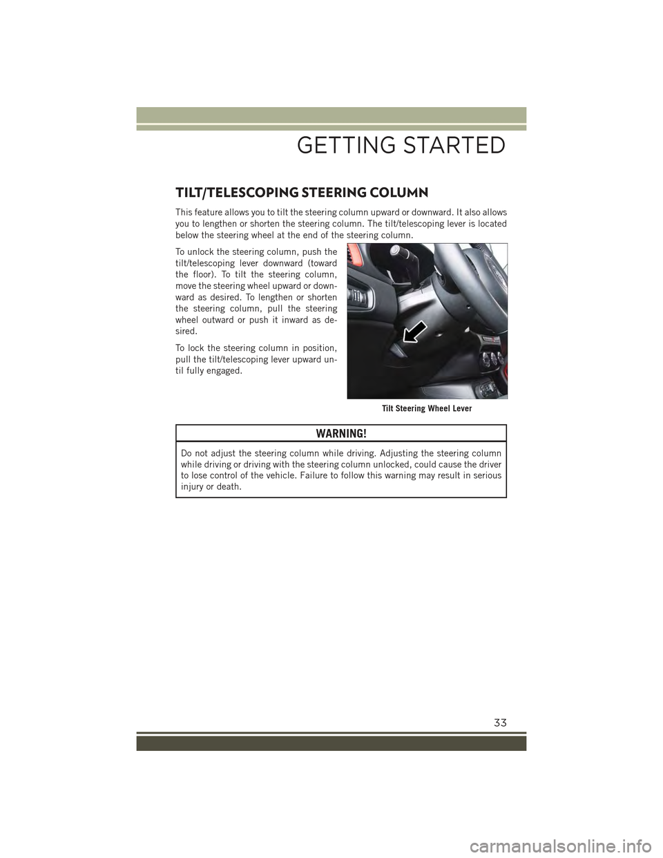
This feature allows you to tilt the steering column upward or downward. It also allows
you to lengthen or shorten the steering column. The tilt/telescoping lever is located
below the steering wheel at the end of the steering column.
To unlock the steering column, push the
tilt/telescoping lever downward (toward
the floor). To tilt the steering column,
move the steering wheel upward or down-
ward as desired. To lengthen or shorten
the steering column, pull the steering
wheel outward or push it inward as de-
sired.
To lock the steering column in position,
pull the tilt/telescoping lever upward un-
til fully engaged.
WARNING!
Do not adjust the steering column while driving. Adjusting the steering column
while driving or driving with the steering column unlocked, could cause the driver
to lose control of the vehicle. Failure to follow this warning may result in serious
injury or death.
Tilt Steering Wheel Lever
GETTING STARTED
33
Page 42 of 220
ELECTRONIC SPEED CONTROL
When engaged, the Electronic Speed Control takes over accelerator operations at
speeds greater than 25 mph (40 km/h).
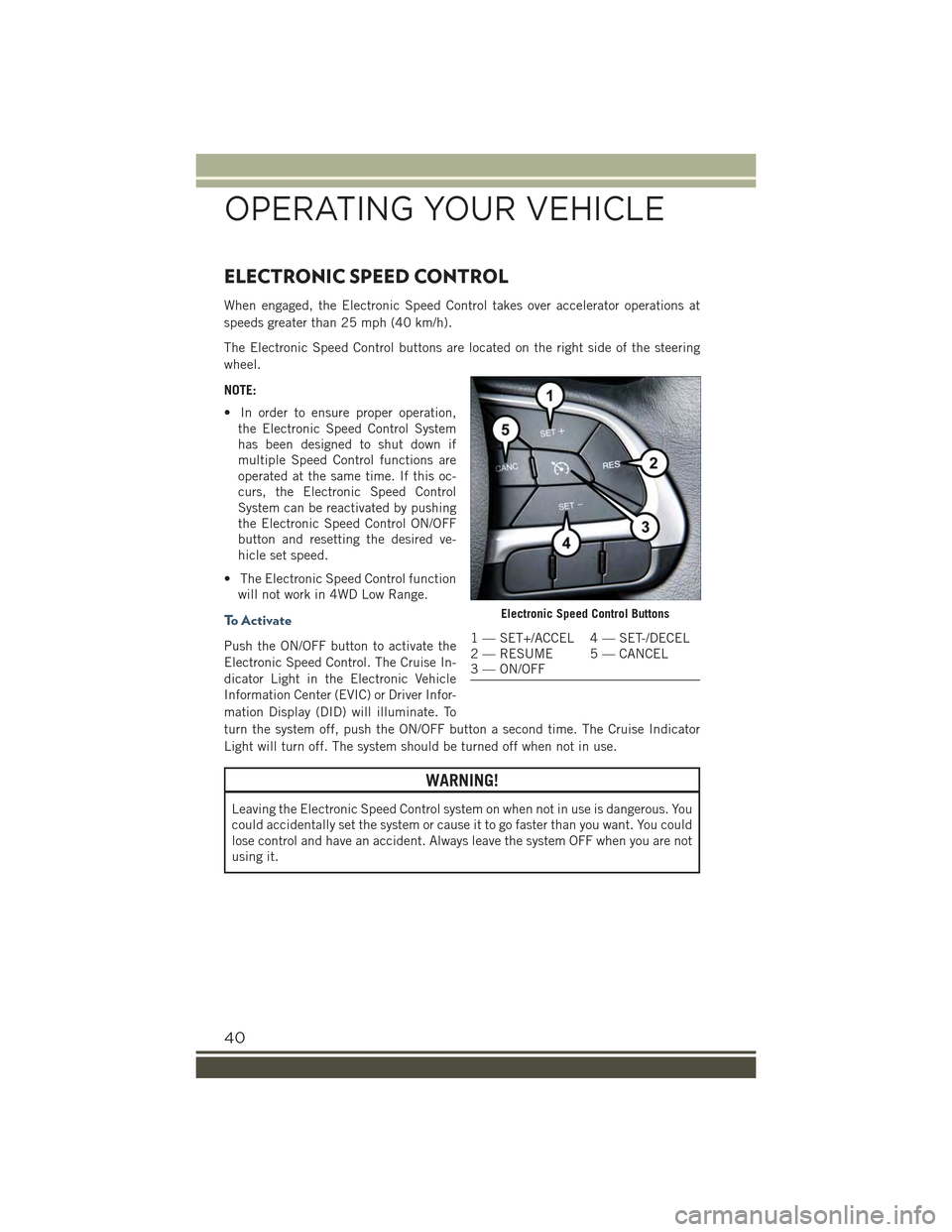
The Electronic Speed Control buttons are located on the right side of the steering
wheel.
NOTE:
• In order to ensure proper operation,
the Electronic Speed Control System
has been designed to shut down if
multiple Speed Control functions are
operated at the same time. If this oc-
curs, the Electronic Speed Control
System can be reactivated by pushing
the Electronic Speed Control ON/OFF
button and resetting the desired ve-
hicle set speed.
• The Electronic Speed Control function
will not work in 4WD Low Range.
To A c t i v a t e
Push the ON/OFF button to activate the
Electronic Speed Control. The Cruise In-
dicator Light in the Electronic Vehicle
Information Center (EVIC) or Driver Infor-
mation Display (DID) will illuminate. To
turn the system off, push the ON/OFF button a second time. The Cruise Indicator
Light will turn off. The system should be turned off when not in use.
WARNING!
Leaving the Electronic Speed Control system on when not in use is dangerous. You
could accidentally set the system or cause it to go faster than you want. You could
lose control and have an accident. Always leave the system OFF when you are not
using it.
Electronic Speed Control Buttons
1 — SET+/ACCEL 4 — SET-/DECEL2 — RESUME 5 — CANCEL3 — ON/OFF
OPERATING YOUR VEHICLE
40
Page 57 of 220
Small Vehicles And/Or Not Aligned To The Lane
The system is not able to detect the presence of vehicles that are in front of the car
but placed outside the field of action of the radar sensor and could therefore not react
in the presence of small vehicles such as bicycles or motorcycles.
Lane Changing Of Other Vehicles
Vehicles that suddenly change lane, while standing in the traffic lane of their car and
inside the field of action of the radar sensor may cause the intervention of the system.
Passing Of Vehicles In An Oncoming Intersection
The system could temporarily react to a vehicle that crossed the range of the radar
sensor, in an oncoming intersection.
LANESENSE
LaneSense Operation
The LaneSense system is operational at speeds above 37 mph (60 km/h) and below
112 mph (180 km/h). The LaneSense system uses a forward looking camera to
detect lane markings and measure vehicle position within the lane boundaries.
When both lane markings are detected and the driver unintentionally drifts out of the
lane (no turn signal applied), the LaneSense system provides a haptic warning in the
form of torque applied to the steering wheel to prompt the driver to remain within the
lane boundaries. If the driver continues to unintentionally drift out of the lane, the
LaneSense system provides a visual warning through the Electronic Vehicle Informa-
tion Center (EVIC) or Driver Information Display (DID) to prompt the driver to remain
within the lane boundaries.
The driver may manually override the haptic warning by applying torque into the
steering wheel at any time.
When only a single lane marking is detected and the driver unintentionally drifts
across the lane marking (no turn signal applied), the LaneSense system provides a
visual warning through the EVIC/DID to prompt the driver to remain within the lane.
When only a single lane marking is detected, a haptic (torque) warning will not be
provided.
NOTE:
When operating conditions have been met, the LaneSense system will monitor if the
driver’s hands are on the steering wheel and provides an audible warning to the driver
when the driver’s hands are not detected on the steering wheel. The system will
cancel if the driver does not return their hands to the wheel.
OPERATING YOUR VEHICLE
55
Page 58 of 220
Turning LaneSense ON Or OFF
The default status of LaneSense is “OFF”.
The LaneSense button is located on the switch panel below the Uconnect®display.
To turn the LaneSense system ON, push the LaneSense button
(LED turns on). A “Lane Sense On” message is shown in the
EVIC/DID.
To turn the LaneSense system OFF, push the LaneSense button
once (LED turns off).
NOTE:
The LaneSense system will retain the last system state ON or OFF from the last
ignition cycle when the ignition is changed to the ON/RUN position.
LaneSense Warning Message
The LaneSense system will indicate the current lane drift condition through the
Electronic Vehicle Information Center (EVIC) or Driver Information Display (DID).
3.5 EVIC Screen — If Equipped
When the LaneSense system is ON, the lane lines are gray when both of the lane
boundaries have not been detected and the LaneSense indicator is solid white.
Left Lane Departure — Only Left Lane Detected
• When the LaneSense system is ON, the LaneSense indicator is solid white when
only the left lane marking has been detected and the system is ready to provide
visual warnings in the EVIC if an unintentional lane departure occurs.
• When the LaneSense system senses the lane has been approached and is in a lane
departure situation, the left thick lane line flashes from white to gray, the left thin
line remains solid white and the LaneSense indicator changes from solid white to
flashing yellow.
NOTE:
The LaneSense system operates with the similar behavior for a right lane depar-
ture when only the right lane marking has been detected.
Left Lane Departure — Both Lanes Detected
• When the LaneSense system is ON, the lane lines turn from gray to white to
indicate that both of the lane markings have been detected. The LaneSense
indicator is solid green when both lane markings have been detected and the
system is “armed” to provide visual warnings in the EVIC and a torque warning in
the steering wheel if an unintentional lane departure occurs.
• When the LaneSense system senses a lane drift situation, the left thick lane line
and the left thin line turn solid white. The LaneSense indicator changes from solid
green to solid yellow. At this time torque is applied to the steering wheel in the
opposite direction of the lane boundary.
OPERATING YOUR VEHICLE
56
Page 59 of 220
For example: If approaching the left side of the lane, the steering wheel will turn to
the right.
• When the LaneSense system senses the lane has been approached and is in a lane
departure situation, the left thick lane line flashes from white to gray, the left thin
line remains solid white and the LaneSense indicator changes from solid yellow to
flashing yellow. At this time, torque is applied to the steering wheel in the opposite
direction of the lane boundary.
For example: If approaching the left side of the lane, the steering wheel will turn to
the right.
NOTE:
The LaneSense system operates with the similar behavior for a right lane departure.
7.0 DID Screen — If Equipped
When the LaneSense system is ON, the lane lines are gray when both of the lane
boundaries have not been detected and the LaneSense indicator is solid white.
Left Lane Departure — Only Left Lane Detected
• When the LaneSense system is ON, the LaneSense indicator is solid white when
only the left lane marking has been detected and the system is ready to provide
visual warnings in the DID if an unintentional lane departure occurs.
• When the LaneSense system senses the lane has been approached and is in a lane
departure situation, the left thick lane line flashes yellow (on/off), the left thin line
remains solid yellow and the LaneSense indicator changes from solid white to
flashing yellow.
NOTE:
The LaneSense system operates with the similar behavior for a right lane depar-
ture when only the right lane marking has been detected.
Left Lane Departure — Both Lanes Detected
• When the LaneSense system is ON, the lane lines turn from gray to white to
indicate that both of the lane markings have been detected. The LaneSense
indicator is solid green when both lane markings have been detected and the
system is “armed” to provide visual warnings in the DID and a torque warning in
the steering wheel if an unintentional lane departure occurs.
• When the LaneSense system senses a lane drift situation, the left thick lane line
and left thin line turn solid yellow. The LaneSense indicator changes from solid
green to solid yellow. At this time torque is applied to the steering wheel in the
opposite direction of the lane boundary.
For example: If approaching the left side of the lane the steering wheel will turn to the
right.
OPERATING YOUR VEHICLE
57