fuse JEEP WAGONEER 2023 Owners Manual
[x] Cancel search | Manufacturer: JEEP, Model Year: 2023, Model line: WAGONEER, Model: JEEP WAGONEER 2023Pages: 396, PDF Size: 15.17 MB
Page 8 of 396
6
SAFETY
SAFETY FEATURES........................................................... 239
Anti-Lock Brake System (ABS) ................................. 239Rear Seat Reminder Alert (RSRA) ............................ 240
Drowsy Driver Detection (DDD) — If Equipped ........ 240
Electronic Brake Control (EBC) System .................. 241
AUXILIARY DRIVING SYSTEMS ...................................... 247 Blind Spot Monitoring (BSM) .................................... 247
Forward Collision Warning (FCW)
With Mitigation .......................................................... 250
Tire Pressure Monitoring System (TPMS) ................ 252
OCCUPANT RESTRAINT SYSTEMS ................................ 256 Occupant Restraint Systems Features ................... 256Important Safety Precautions .................................. 256Seat Belt Systems .................................................... 257
Supplemental Restraint Systems (SRS) .................. 264Child Restraints ........................................................ 275
SAFETY TIPS ..................................................................... 287 Transporting Passengers .......................................... 287
Transporting Pets ...................................................... 287Connected Vehicles .................................................. 287
Safety Checks You Should Make Inside
The Vehicle ............................................................... 287
Periodic Safety Checks You Should Make
Outside The Vehicle .................................................. 289
Exhaust Gas .............................................................. 289Carbon Monoxide Warnings ..................................... 289
IN CASE OF EMERGENCY
HAZARD WARNING FLASHERS ..................................... 290
ASSIST AND SOS SYSTEM— IF EQUIPPED ................... 290
JACKING AND TIRE CHANGING...................................... 293 Preparations For Jacking ......................................... 293
Jack And Tools Location ........................................... 294Spare Tire Stowage................................................... 295
Spare Tire Removal .................................................. 295Jacking Instructions ................................................. 296
JUMP STARTING ............................................................. 300 Preparations For Jump Start .................................... 300Jump Starting Procedure.......................................... 301
REFUELING IN EMERGENCY........................................... 302
IF YOUR ENGINE OVERHEATS ........................................ 303
MANUAL PARK RELEASE .............................................. 303
FREEING A STUCK VEHICLE .......................................... 305
TOWING A DISABLED VEHICLE ..................................... 306 Rear-Wheel Drive Models......................................... 307
Four-Wheel Drive Models ......................................... 307
Emergency Tow Hooks — If Equipped ..................... 308
ENHANCED ACCIDENT RESPONSE SYSTEM
(EARS) .............................................................................. 308
EVENT DATA RECORDER (EDR) ..................................... 308
SERVICING AND MAINTENANCE
SCHEDULED SERVICING .................................................. 309 Maintenance Plan ..................................................... 310
ENGINE COMPARTMENT ................................................. 313 3.0L Engine................................................................ 313
5.7L Engine................................................................ 314
6.4L Engine................................................................ 315
Checking Oil Level — 3.0L Engines .......................... 316
Checking Oil Level — 5.7L & 6.4L Engines .............. 317
Adding Washer Fluid ................................................ 317
Maintenance-Free Battery ....................................... 318Pressure Washing ..................................................... 318
VEHICLE MAINTENANCE .................................................. 318 Engine Oil .................................................................. 319
Engine Oil Filter ....................................................... 319
Engine Air Cleaner Filter ........................................ 319Air Conditioner Maintenance ................................. 320
Accessory Drive Belt Inspection ............................... 323Body Lubrication ....................................................... 323
Windshield Wiper Blades ......................................... 324
Exhaust System ........................................................ 325
Cooling System .......................................................... 326
Brake System ........................................................... 328
Automatic Transmission ........................................... 329
Front/Rear Axle Fluid ............................................... 330Transfer Case ............................................................ 330Fuses .......................................................................... 331Bulb Replacement .................................................... 349
23_WS_OM_EN_USC_t.book Page 6
Page 81 of 396
GETTING TO KNOW YOUR VEHICLE79
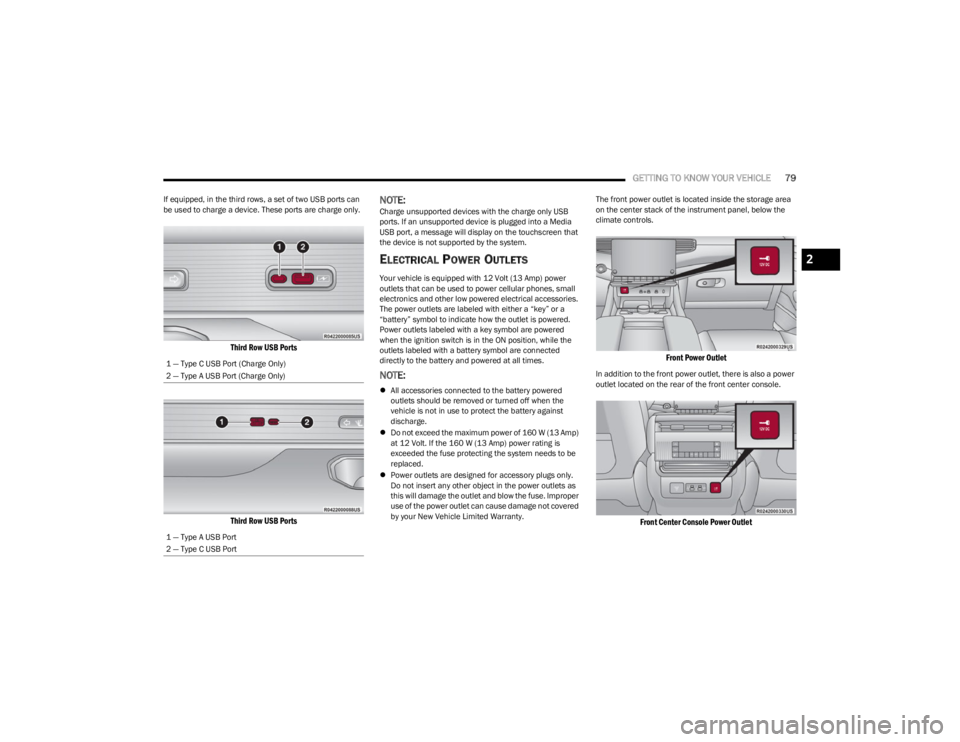
If equipped, in the third rows, a set of two USB ports can
be used to charge a device. These ports are charge only.
Third Row USB Ports
Third Row USB Ports
NOTE:Charge unsupported devices with the charge only USB
ports. If an unsupported device is plugged into a Media
USB port, a message will display on the touchscreen that
the device is not supported by the system.
ELECTRICAL POWER OUTLETS
Your vehicle is equipped with 12 Volt (13 Amp) power
outlets that can be used to power cellular phones, small
electronics and other low powered electrical accessories.
The power outlets are labeled with either a “key” or a
“battery” symbol to indicate how the outlet is powered.
Power outlets labeled with a key symbol are powered
when the ignition switch is in the ON position, while the
outlets labeled with a battery symbol are connected
directly to the battery and powered at all times.
NOTE:
All accessories connected to the battery powered
outlets should be removed or turned off when the
vehicle is not in use to protect the battery against
discharge.
Do not exceed the maximum power of 160 W (13 Amp)
at 12 Volt. If the 160 W (13 Amp) power rating is
exceeded the fuse protecting the system needs to be
replaced.
Power outlets are designed for accessory plugs only.
Do not insert any other object in the power outlets as
this will damage the outlet and blow the fuse. Improper
use of the power outlet can cause damage not covered
by your New Vehicle Limited Warranty. The front power outlet is located inside the storage area
on the center stack of the instrument panel, below the
climate controls.
Front Power Outlet
In addition to the front power outlet, there is also a power
outlet located on the rear of the front center console.
Front Center Console Power Outlet
1 — Type C USB Port (Charge Only)
2 — Type A USB Port (Charge Only)
1 — Type A USB Port
2 — Type C USB Port
2
23_WS_OM_EN_USC_t.book Page 79
Page 82 of 396
80GETTING TO KNOW YOUR VEHICLE
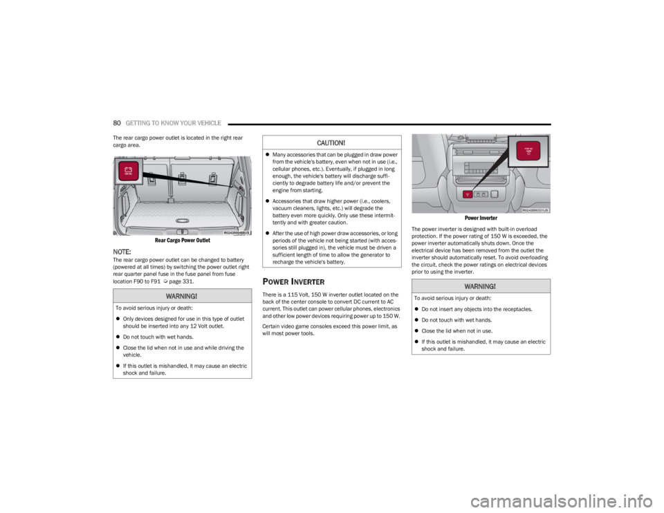
The rear cargo power outlet is located in the right rear
cargo area.
Rear Cargo Power Outlet
NOTE:The rear cargo power outlet can be changed to battery
(powered at all times) by switching the power outlet right
rear quarter panel fuse in the fuse panel from fuse
location F90 to F91
Úpage 331.POWER INVERTER
There is a 115 Volt, 150 W inverter outlet located on the
back of the center console to convert DC current to AC
current. This outlet can power cellular phones, electronics
and other low power devices requiring power up to 150 W.
Certain video game consoles exceed this power limit, as
will most power tools.
Power Inverter
The power inverter is designed with built-in overload
protection. If the power rating of 150 W is exceeded, the
power inverter automatically shuts down. Once the
electrical device has been removed from the outlet the
inverter should automatically reset. To avoid overloading
the circuit, check the power ratings on electrical devices
prior to using the inverter.
WARNING!
To avoid serious injury or death:
Only devices designed for use in this type of outlet
should be inserted into any 12 Volt outlet.
Do not touch with wet hands.
Close the lid when not in use and while driving the
vehicle.
If this outlet is mishandled, it may cause an electric
shock and failure.
CAUTION!
Many accessories that can be plugged in draw power
from the vehicle's battery, even when not in use (i.e.,
cellular phones, etc.). Eventually, if plugged in long
enough, the vehicle's battery will discharge suffi -
ciently to degrade battery life and/or prevent the
engine from starting.
Accessories that draw higher power (i.e., coolers,
vacuum cleaners, lights, etc.) will degrade the
battery even more quickly. Only use these intermit -
tently and with greater caution.
After the use of high power draw accessories, or long
periods of the vehicle not being started (with acces -
sories still plugged in), the vehicle must be driven a
sufficient length of time to allow the generator to
recharge the vehicle's battery.
WARNING!
To avoid serious injury or death:
Do not insert any objects into the receptacles.
Do not touch with wet hands.
Close the lid when not in use.
If this outlet is mishandled, it may cause an electric
shock and failure.
23_WS_OM_EN_USC_t.book Page 80
Page 302 of 396

300IN CASE OF EMERGENCY
12. Lower the jack to the fully closed position.
13. Return the Jack and tools back into the jack storage
bin. Reinstall the jack storage cover by firmly pushing
down until the clips lock into position.
14. After 25 miles (40 km), check the lug nut torque with a torque wrench to ensure that all lug nuts are
properly seated against the wheel.
15. Have the road wheel and tire repaired as soon as possible and properly secure the spare tire, jack and
tool kit.
NOTE:Do not drive with the spare tire installed for more than
50 miles (80 km) at a max speed of 50 mph (80 km/h).
JUMP STARTING
If your vehicle has a discharged battery, it can be jump
started using a set of jumper cables and a battery in
another vehicle, or by using a portable battery booster
pack. Jump starting can be dangerous if done improperly,
so please follow the procedures in this section carefully.
NOTE:When using a portable battery booster pack, follow the
manufacturer's operating instructions and precautions.
PREPARATIONS FOR JUMP START
The battery in your vehicle is located in the front of the
engine compartment, behind the left headlight assembly.
Positive (+) Jump Starting Post
NOTE:The positive (+) battery post may be covered with a
protective cap. Lift up on the cap to gain access to the
positive battery post. Do not jump off fuses. Only jump
directly off positive post which has a positive (+) symbol on
or around the post.
See the following steps to prepare for jump starting:
1. Apply the parking brake, shift the automatic transmission into PARK (P) and turn the ignition OFF.
2. Turn off the heater, radio, and all electrical accessories.
3. If using another vehicle to jump start the battery, park the vehicle within the jumper cables’ reach, apply the
parking brake and make sure the ignition is OFF.
NOTE:Be sure that the disconnected cable ends do not touch
each other, or either vehicle, until properly connected for
jump starting.
WARNING!
Do not attempt jump starting if the battery is frozen. It
could rupture or explode and cause personal injury.
CAUTION!
Do not use a portable battery booster pack or any other
booster source with a system voltage greater than
12 Volts or damage to the battery, starter motor,
alternator or electrical system may occur.
WARNING!
Do not allow vehicles to touch each other as this could
establish a ground connection and personal injury
could result.
23_WS_OM_EN_USC_t.book Page 300
Page 315 of 396
SERVICING AND MAINTENANCE313
ENGINE COMPARTMENT
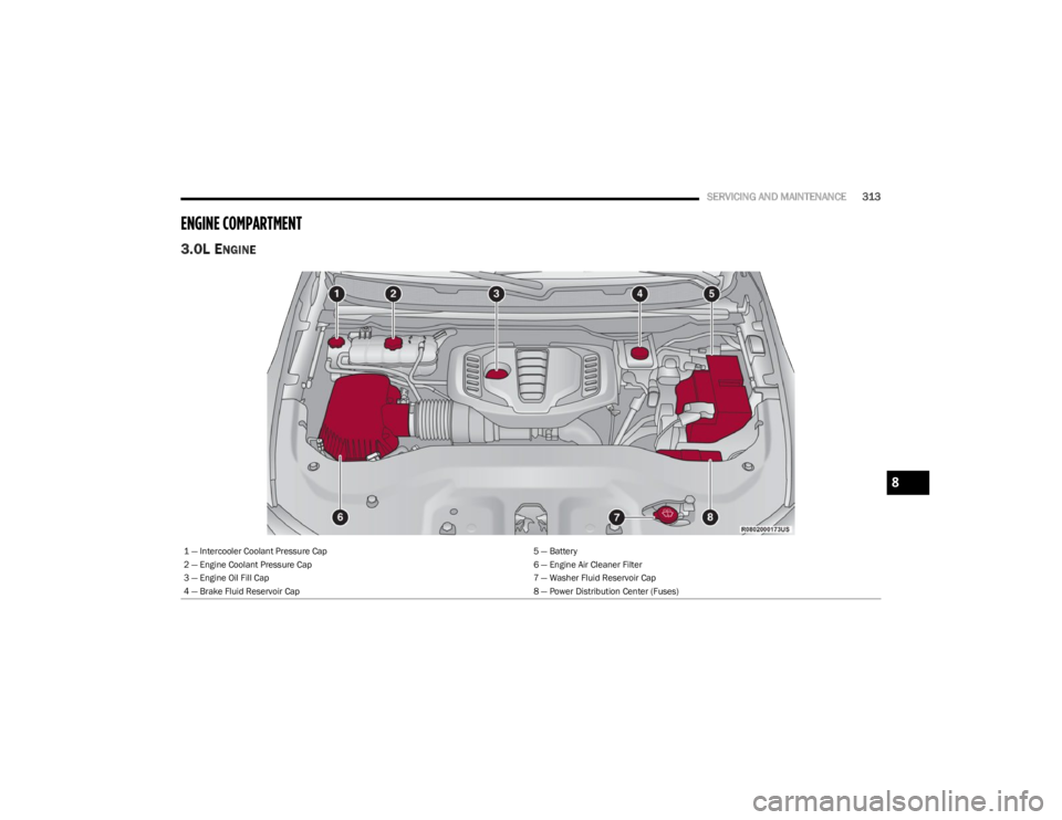
3.0L ENGINE
1 — Intercooler Coolant Pressure Cap 5 — Battery
2 — Engine Coolant Pressure Cap 6 — Engine Air Cleaner Filter
3 — Engine Oil Fill Cap 7 — Washer Fluid Reservoir Cap
4 — Brake Fluid Reservoir Cap 8 — Power Distribution Center (Fuses)
8
23_WS_OM_EN_USC_t.book Page 313
Page 316 of 396
314SERVICING AND MAINTENANCE
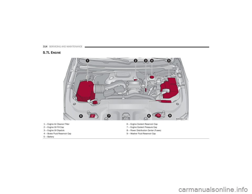
5.7L ENGINE
1 — Engine Air Cleaner Filter 6 — Engine Coolant Reservoir Cap
2 — Engine Oil Fill Cap 7 — Engine Coolant Pressure Cap
3 — Engine Oil Dipstick 8 — Power Distribution Center (Fuses)
4 — Brake Fluid Reservoir Cap 9 — Washer Fluid Reservoir Cap
5 — Battery
23_WS_OM_EN_USC_t.book Page 314
Page 317 of 396
SERVICING AND MAINTENANCE315
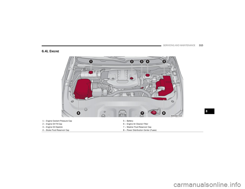
6.4L ENGINE
1 — Engine Coolant Pressure Cap 5 — Battery
2 — Engine Oil Fill Cap 6 — Engine Air Cleaner Filter
3 — Engine Oil Dipstick 7 — Washer Fluid Reservoir Cap
4 — Brake Fluid Reservoir Cap 8 — Power Distribution Center (Fuses)
8
23_WS_OM_EN_USC_t.book Page 315
Page 333 of 396
SERVICING AND MAINTENANCE331
FUSES
General Information
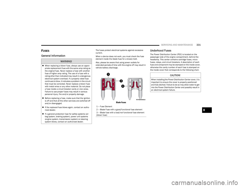
The fuses protect electrical systems against excessive
current.
When a device does not work, you must check the fuse
element inside the blade fuse for a break/melt.
Also, please be aware that using power outlets for
extended periods of time with the engine off may result in
vehicle battery discharge.
Blade Fuses
Underhood Fuses
The Power Distribution Center (PDC) is located on the
passenger side of the engine compartment, behind the
headlamp. This center contains cartridge fuses, micro
fuses, relays, and circuit breakers. A description of each
fuse and component may be stamped on the inside cover,
otherwise the cavity number of each fuse is stamped on
the inside cover that corresponds to the following chart.
WARNING!
When replacing a blown fuse, always use an appro -
priate replacement fuse with the same amp rating as
the original fuse. Never replace a fuse with another
fuse of higher amp rating. The use of a fuse with a
rating other than indicated may result in a dangerous
electrical system overload. If a properly rated fuse
continues to blow, it indicates a problem in the circuit
that must be corrected. Never replace a blown fuse
with metal wires or any other material. Do not place
a fuse inside a circuit breaker cavity or vice versa.
Failure to use proper fuses may result in serious
personal injury, fire and/or property damage.
Before replacing a fuse, make sure that the ignition
is off and that all the other services are switched off
and/or disengaged.
If the replaced fuse blows again, contact an autho -
rized dealer.
If a general protection fuse for safety systems (air
bag system, braking system), power unit systems
(engine system, transmission system) or steering
system blows, contact an authorized dealer.
1 — Fuse Element
2 — Blade Fuse with a good/functional fuse element
3 — Blade fuse with a bad/not functional fuse element
(blown fuse)
CAUTION!
When installing the Power Distribution Center cover, it is
important to ensure the cover is properly positioned
and fully latched. Failure to do so may allow water to get
into the Power Distribution Center and possibly result in
an electrical system failure.
8
23_WS_OM_EN_USC_t.book Page 331
Page 334 of 396

332SERVICING AND MAINTENANCE
Power Distribution Center
Cavity Cartridge Fuse Micro Fuse Description
* If Equipped
F01 ––Crank Batt
F02 80 Amp Gray –Elec Pwr Str #1
F03 500 Amp Gray –Starter
23_WS_OM_EN_USC_t.book Page 332
Page 335 of 396
SERVICING AND MAINTENANCE333
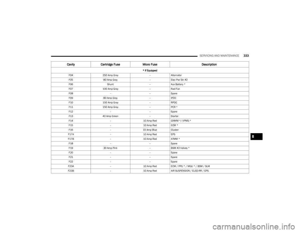
F04250 Amp Gray –Alternator
F05 80 Amp Gray –Elec Pwr Str #2
F06 Shunt –Aux Battery *
F07 100 Amp Gray –Rad Fan
F08 ––Spare
F09 80 Amp Gray –IPDC
F10 150 Amp Gray –RPDC
F11 150 Amp Gray –PCR *
F12 ––Spare
F13 40 Amp Green –Starter
F14 –10 Amp RedGNMM */ VPMS *
F15 –10 Amp RedECM *
F16 –15 Amp BlueCluster
F17A –10 Amp RedEPS
F17B –10 Amp RedATMM *
F18 ––Spare
F19 30 Amp Pink –BSM #2 Valves *
F20 ––Spare
F21 ––Spare
F22 ––Spare
F23A –10 Amp RedECM / PPU * / MGU * / BSM / SLM
F23B –10 Amp RedAIR SUSPENSION / ELSD-RR / EPS
Cavity Cartridge Fuse Micro Fuse Description
* If Equipped
8
23_WS_OM_EN_USC_t.book Page 333