light KIA Optima Hybrid 2012 3.G Owner's Manual
[x] Cancel search | Manufacturer: KIA, Model Year: 2012, Model line: Optima Hybrid, Model: KIA Optima Hybrid 2012 3.GPages: 394, PDF Size: 8.63 MB
Page 341 of 394
Maintenance
48
7
Intended Outboard Sidewall: The
side of an asymmetrical tire, that
must always face outward when
mounted on a vehicle.
Kilopascal (kPa): The metric unit for
air pressure.
Load Index: An assigned number
ranging from 1 to 279 that corre-
sponds to the load carrying capacity
of a tire.
Maximum Inflation Pressure: The
maximum air pressure to which a
cold tire may be inflated. The maxi-
mum air pressure is molded onto the
sidewall.
Maximum Load Rating: The load
rating for a tire at the maximum per-
missible inflation pressure for that
tire.
Maximum Loaded Vehicle Weight:
The sum of curb weight; accessory
weight; vehicle capacity weight; and
production options weight.
Normal Occupant Weight: The
number of occupants a vehicle is
designed to seat multiplied by 68 kg
(150 pounds). Occupant Distribution:
Designated
seating positions.
Outward Facing Sidewall: The side
of a asymmetrical tire that has a par-
ticular side that faces outward when
mounted on a vehicle. The outward
facing sidewall bears white lettering
or bears manufacturer, brand, and/or
model name molding that is higher or
deeper than the same moldings on
the inner facing sidewall.
Passenger (P-Metric) Tire: A tire
used on passenger cars and some
light duty trucks and multipurpose
vehicles.
Recommended Inflation Pressure:
Vehicle manufacturer's recommend-
ed tire inflation pressure and shown
on the tire placard.
Radial Ply Tire: A pneumatic tire in
which the ply cords that extend to the
beads are laid at 90 degrees to the
centerline of the tread.
Rim: A metal support for a tire and
upon which the tire beads are seat-
ed.
Sidewall: The portion of a tire
between the tread and the bead. Speed Rating:
An alphanumeric
code assigned to a tire indicating the
maximum speed at which a tire can
operate.
Traction: The friction between the
tire and the road surface. The
amount of grip provided.
Tread: The portion of a tire that
comes into contact with the road.
Treadwear Indicators: Narrow
bands, sometimes called "wear
bars," that show across the tread of a
tire when only 2/32 inch of tread
remains.
UTQGS: Uniform Tire Quality
Grading Standards, a tire information
system that provides consumers with
ratings for a tire's traction, tempera-
ture and treadwear. Ratings are
determined by tire manufacturers
using government testing proce-
dures. The ratings are molded into
the sidewall of the tire.
Vehicle Capacity Weight: The num-
ber of designated seating positions
multiplied by 68 kg (150 lbs.) plus the
rated cargo and luggage load.
Page 344 of 394
751
Maintenance
FUSES
A vehicle’s electrical system is protected
from electrical overload damage by
fuses.
This vehicle has 2 fuse panels, one locat-
ed in the driver’s side panel bolster, the
other in the engine compartment near
the battery.
If any of your vehicle’s lights, acces-
sories, or controls do not work, check the
appropriate circuit fuse. If a fuse has
blown, the element inside the fuse will
melt.
If the electrical system does not work,
first check the driver’s side fuse panel.
Always replace a blown fuse with one of
the same rating.
If the replacement fuse blows, this indi-
cates an electrical problem. Avoid using
the system involved and immediately
consult an authorized Kia dealer.
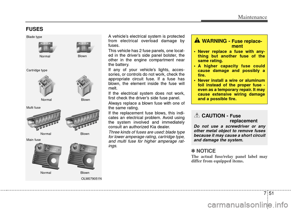
Three kinds of fuses are used: blade typefor lower amperage rating, cartridge type,and multi fuse for higher amperage rat-ings.
✽ ✽ NOTICE
The actual fuse/relay panel label may
differ from equipped items.
WARNING - Fuse replace-
ment
Never replace a fuse with any-
thing but another fuse of the
same rating.
A higher capacity fuse could cause damage and possibly a
fire.
Never install a wire or aluminum foil instead of the proper fuse -
even as a temporary repair. It may
cause extensive wiring damage
and a possible fire.
CAUTION - Fuse
replacement
Do not use a screwdriver or anyother metal object to remove fuses because it may cause a short circuitand damage the system.
OLM079051N
Normal
Normal
Blade type
Cartridge type
Multi fuse
Main fuse Blown
Blown
Normal Blown
Normal Blown
Page 345 of 394
Maintenance
52
7
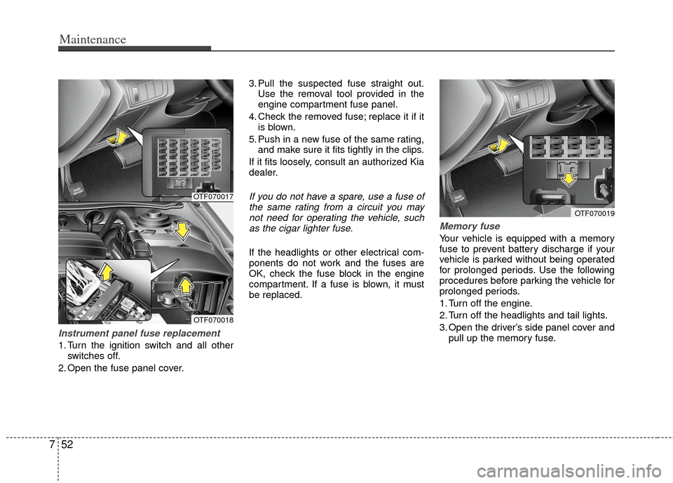
Instrument panel fuse replacement
1. Turn the ignition switch and all other
switches off.
2. Open the fuse panel cover. 3. Pull the suspected fuse straight out.
Use the removal tool provided in the
engine compartment fuse panel.
4. Check the removed fuse; replace it if it is blown.
5. Push in a new fuse of the same rating, and make sure it fits tightly in the clips.
If it fits loosely, consult an authorized Kia
dealer.
If you do not have a spare, use a fuse of the same rating from a circuit you maynot need for operating the vehicle, suchas the cigar lighter fuse.
If the headlights or other electrical com-
ponents do not work and the fuses are
OK, check the fuse block in the engine
compartment. If a fuse is blown, it must
be replaced.
Memory fuse
Your vehicle is equipped with a memory
fuse to prevent battery discharge if your
vehicle is parked without being operated
for prolonged periods. Use the following
procedures before parking the vehicle for
prolonged periods.
1. Turn off the engine.
2. Turn off the headlights and tail lights.
3. Open the driver’s side panel cover and pull up the memory fuse.
OTF070019
OTF070017
OTF070018
Page 346 of 394
753
Maintenance
✽
✽NOTICE
• If the memory fuse is pulled up from
the fuse panel, the warning chime,
audio, clock and interior lamps, etc.,
will not operate. Some items must be
reset after replacement. Refer to
“Battery” in this section.
• Even when the memory fuse is pulled up, the battery can still be discharged
by operation of the headlights or other
electrical devices.
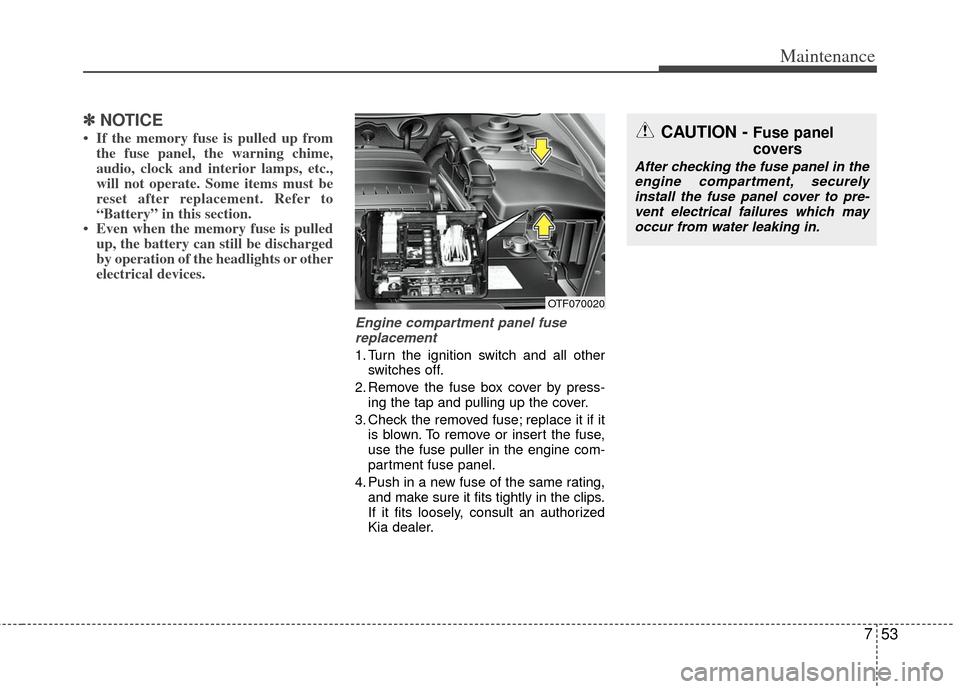
Engine compartment panel fuse
replacement
1. Turn the ignition switch and all other switches off.
2. Remove the fuse box cover by press- ing the tap and pulling up the cover.
3. Check the removed fuse; replace it if it is blown. To remove or insert the fuse,
use the fuse puller in the engine com-
partment fuse panel.
4. Push in a new fuse of the same rating, and make sure it fits tightly in the clips.
If it fits loosely, consult an authorized
Kia dealer.
CAUTION - Fuse panel
covers
After checking the fuse panel in theengine compartment, securely install the fuse panel cover to pre-vent electrical failures which mayoccur from water leaking in.
OTF070020
Page 349 of 394
Maintenance
56
7
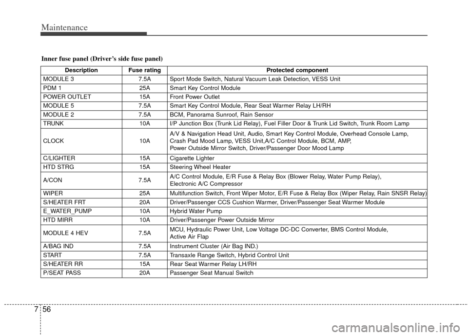
Inner fuse panel (Driver’s side fuse panel)
Description Fuse rating Protected component
MODULE 3 7.5A Sport Mode Switch, Natural Vacuum Leak Detection, VESS Unit
PDM 1 25A Smart Key Control Module
POWER OUTLET 15A Front Power Outlet
MODULE 5 7.5A Smart Key Control Module, Rear Seat Warmer Relay LH/RH
MODULE 2 7.5A BCM, Panorama Sunroof, Rain Sensor
TRUNK 10A I/P Junction Box (Trunk Lid Relay), Fuel Filler Door & Trunk Lid Switch, Trunk Room Lamp
CLOCK 10AA/V & Navigation Head Unit, Audio, Smart Key Control Module, Overhead Console Lamp,
Crash Pad Mood Lamp, VESS Unit,A/C Control Module, BCM, AMP,
Power Outside Mirror Switch, Driver/Passenger Door Mood Lamp
C/LIGHTER 15A Cigarette Lighter
HTD STRG 15A Steering Wheel Heater
A/CON 7.5AA/C Control Module, E/R Fuse & Relay Box (Blower Relay, Water Pump Relay),
Electronic A/C Compressor
WIPER 25A Multifunction Switch, Front Wiper Motor, E/R Fuse & Relay Box (Wiper Relay, Rain SNSR Relay)
S/HEATER FRT 20A Driver/Passenger CCS Cushion Warmer, Driver/Passenger Seat Warmer Module
E_WATER_PUMP 10A Hybrid Water Pump
HTD MIRR 10A Driver/Passenger Power Outside Mirror
MODULE 4 HEV 7.5AMCU, Hydraulic Power Unit, Low Voltage DC-DC Converter, BMS Control Module,
Active Air Flap
A/BAG IND 7.5A Instrument Cluster (Air Bag IND.)
START 7.5A Transaxle Range Switch, Hybrid Control Unit
S/HEATER RR 15A Rear Seat Warmer Relay LH/RH
P/SEAT PASS 20A Passenger Seat Manual Switch
Page 350 of 394

757
Maintenance
DescriptionFuse rating Protected component
MODULE 1 7.5AHead Lamp Leveling Device Actuator LH/RH, Auto Head Lamp Leveling Device Module,
Driver IMS Module, BCM, Front Seat Warmer & CCS Switch,
Driver/Passenger CCS Control Module, Driver/Passenger Seat Warmer Module, Audio,
A/C Control Module, Electro Chromic Mirror, Lane Keeping Assist Module, Instrument Cluster
HCU 20A Hybrid Control Unit
A/BAG 15A Telltale Lamp, SRS Control Module, Passenger Weight Classification Sensor
P/WDW LH 25A I/P Junction Box (Power Window LH Relay), Driver Safety Power Window Module
AMP 30A AMP
PDM 2 7.5A Start Stop Button Switch, Smart Key Control Module, Fob Holder, Stop Lamp Switch
BMS 10A BMS Control Module
MDPS 10A EPS Control Module, Crash Pad Switch, Tire Pressure Monitoring Module, ATM Lever Indicator
PDM 3 7.5A Smart Key Control Module
P/WDW RH 25A I/P Junction Box (Power Window RH Relay), Passenger Safety Power Window Module
P/SEAT DRV 30A Driver IMS Module, Driver Seat Manual Switch, Driver Lumbar Support Switch
DR LOCK 20ATwo Turn Unlock Relay, I/P Junction Box (Door Lock Relay, Door Unlock Relay,
Turn Signal Lamp Sound Relay)
SUNROOF 20A Panorama Sunroof
IG 1 20A E/R Fuse & Relay Box (Fuse : ESC 3 10A, TCU 2 15A, ECU 4 10A, OPCU 2 10A)
POWER
CONNECTOR AUDIO 15A A/V & Navigation Head Unit, Audio
ROOM LP 10A Driver/Passenger Smart Key Outside Handle, Driver IMS Module, Lamp Auto Cut Relay,
Driver/Passenger Door Scuff Lamp, A/C Control Module, Data Link Connector, RF Receiver,
BCM, Electro Chromic Mirror, Instrument Cluster, Auto Light & Photo Sensor,
Tire Pressure Monitoring Module
Page 354 of 394
761
Maintenance
APPEARANCE CARE
Exterior care
Exterior general caution
It is very important to follow the label
directions when using any chemical
cleaner or polish. Read all warning and
caution statements that appear on the
label.
Finish maintenance
Washing
To help protect your vehicle’s finish from
rust and deterioration, wash it thoroughly
and frequently at least once a month with
lukewarm or cold water.
If you use your vehicle for off-road driv-
ing, you should wash it after each off-
road trip. Pay special attention to the
removal of any accumulation of salt, dirt,
mud, and other foreign materials. Make
sure the drain holes in the lower edges of
the doors and rocker panels are kept
clear and clean.
Insects, tar, tree sap, bird droppings,
industrial pollution and similar deposits
can damage your vehicle’s finish if not
removed immediately.
Even prompt washing with plain water
may not completely remove all these
deposits. A mild soap, safe for use on
painted surfaces, may be used.
After washing, rinse the vehicle thor-
oughly with lukewarm or cold water. Do
not allow soap to dry on the finish.
After washing the vehicle, test the brakes
while driving slowly to see if they have
been affected by water. If braking per-
formance is impaired, dry the brakes by
applying them lightly while maintaining a
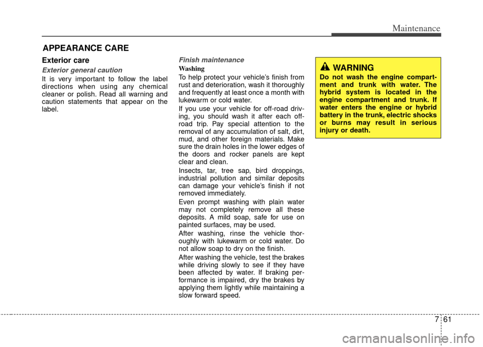
slow forward speed.WARNING
Do not wash the engine compart-
ment and trunk with water. The
hybrid system is located in the
engine compartment and trunk. If
water enters the engine or hybrid
battery in the trunk, electric shocks
or burns may result in serious
injury or death.
Page 366 of 394
83
Specifications, Consumer information, Reporting safety defects
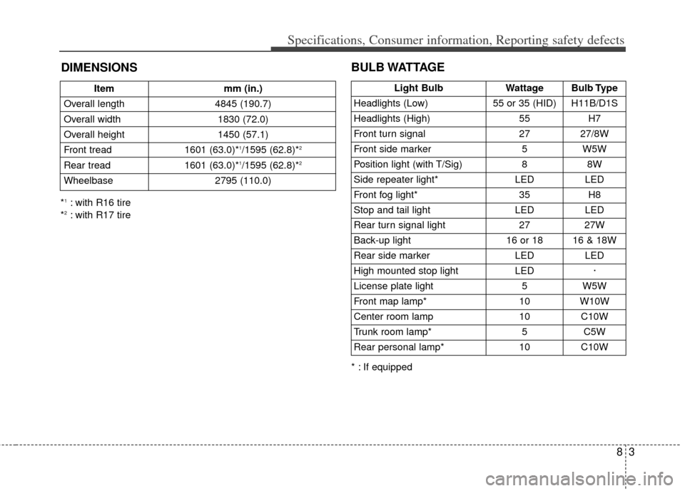
Itemmm (in.)
Overall length 4845 (190.7)
Overall width 1830 (72.0)
Overall height 1450 (57.1)
Front tread 1601 (63.0)*
1/1595 (62.8)*2
Rear tread1601 (63.0)*1/1595 (62.8)*2
Wheelbase 2795 (110.0)
BULB WATTAGE
* : If equipped
*
1: with R16 tire
*2: with R17 tire
DIMENSIONS
Light BulbWattageBulb Type
Headlights (Low)55 or 35 (HID)H11B/D1S
Headlights (High)55H7
Front turn signal2727/8W
Front side marker5W5W
Position light (with T/Sig)88W
Side repeater light* LEDLED
Front fog light*35H8
Stop and tail lightLEDLED
Rear turn signal light 2727W
Back-up light16 or 1816 & 18W
Rear side markerLEDLED
High mounted stop lightLED·
License plate light5W5W
Front map lamp*10W10W
Center room lamp10C10W
Trunk room lamp*5C5W
Rear personal lamp*10C10W
Page 377 of 394
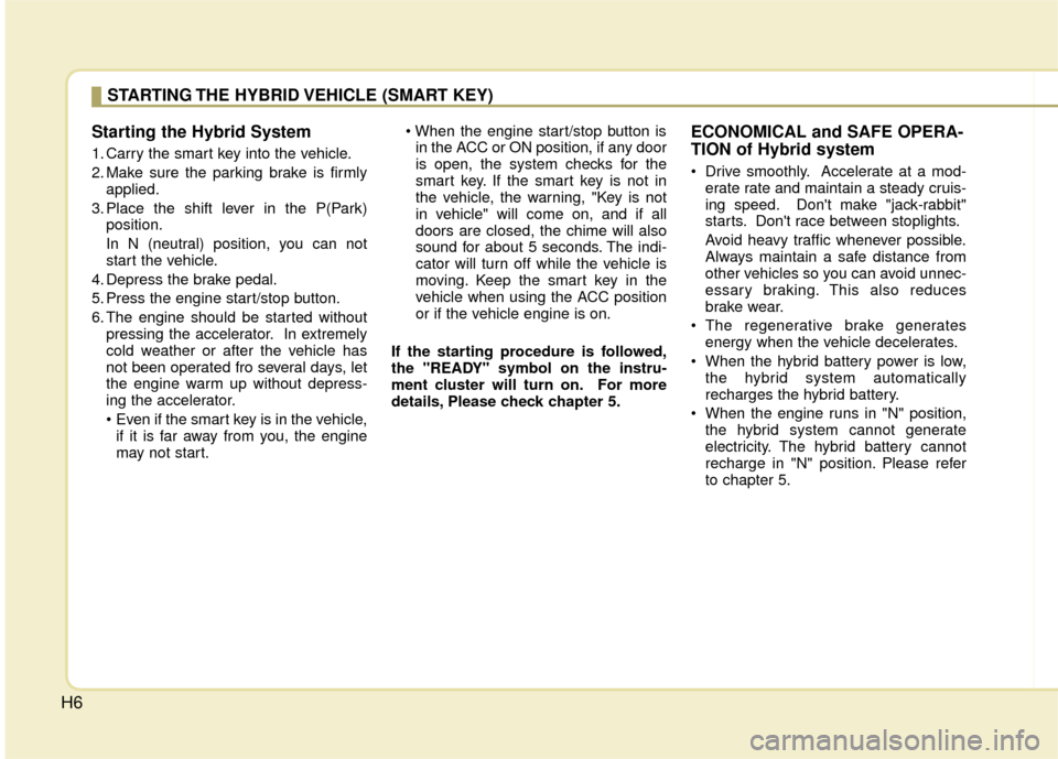
H6Starting the Hybrid System
1. Carry the smart key into the vehicle.
2. Make sure the parking brake is firmly
applied.
3. Place the shift lever in the P(Park) position.
In N (neutral) position, you can not
start the vehicle.
4. Depress the brake pedal.
5. Press the engine start/stop button.
6. The engine should be started without pressing the accelerator. In extremely
cold weather or after the vehicle has
not been operated fro several days, let
the engine warm up without depress-
ing the accelerator.
• Even if the smart key is in the vehicle,if it is far away from you, the engine
may not start.
in the ACC or ON position, if any door
is open, the system checks for the
smart key. If the smart key is not in
the vehicle, the warning, "Key is not
in vehicle" will come on, and if all
doors are closed, the chime will also
sound for about 5 seconds. The indi-
cator will turn off while the vehicle is
moving. Keep the smart key in the
vehicle when using the ACC position
or if the vehicle engine is on.
If the starting procedure is followed,
the "READY" symbol on the instru-
ment cluster will turn on. For more
details, Please check chapter 5.
ECONOMICAL and SAFE OPERA-
TION of Hybrid system
Drive smoothly. Accelerate at a mod- erate rate and maintain a steady cruis-
ing speed. Don't make "jack-rabbit"
starts. Don't race between stoplights.
Avoid heavy traffic whenever possible.
Always maintain a safe distance from
other vehicles so you can avoid unnec-
essary braking. This also reduces
brake wear.
The regenerative brake generates energy when the vehicle decelerates.
When the hybrid battery power is low, the hybrid system automatically
recharges the hybrid battery.
When the engine runs in "N" position, the hybrid system cannot generate
electricity. The hybrid battery cannot
recharge in "N" position. Please refer
to chapter 5.
STARTING THE HYBRID VEHICLE (SMART KEY)
Page 387 of 394
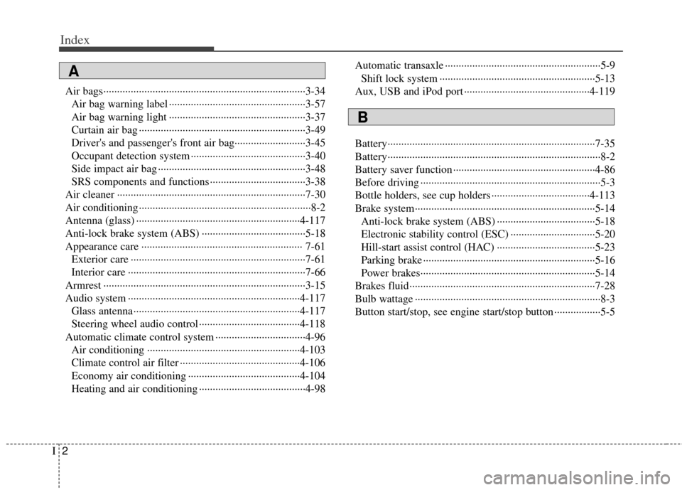
Index
2I
Air bags··················\
··················\
··················\
··················\
··3-34Air bag warning label ··················\
··················\
··············3-57
Air bag warning light ··················\
··················\
··············3-37
Curtain air bag ··················\
··················\
··················\
·······3-49
Driver's and passenger's front air bag··········\
················3-45
Occupant detection system ··················\
··················\
······3-40
Side impact air bag ··················\
··················\
··················\
3-48
SRS components and functions ··················\
·················3-38\
Air cleaner ··················\
··················\
··················\
···············7-30
Air conditioning ··················\
··················\
··················\
·········8-2
Antenna (glass) ··················\
··················\
··················\
······4-117
Anti-lock brake system (ABS) ··················\
··················\
··5-18
Appearance care ··················\
··················\
··················\
····· 7-61 Exterior care ··················\
··················\
··················\
··········7-61
Interior care ··················\
··················\
··················\
···········7-66
Armrest ··················\
··················\
··················\
··················\
··3-15
Audio system ··················\
··················\
··················\
·········4-117 Glass antenna ··················\
··················\
··················\
·······4-117
Steering wheel audio control ··················\
··················\
·4-118
Automatic climate control system ··················\
···············4-96 Air conditioning ··················\
··················\
··················\
··4-103
Climate control air filter ··················\
··················\
········4-106
Economy air conditioning ··················\
··················\
·····4-104
Heating and air conditioning ··················\
··················\
···4-98 Automatic transaxle ··················\
··················\
··················\
···5-9
Shift lock system ··················\
··················\
··················\
···5-13
Aux, USB and iPod port ··················\
··················\
··········4-119
Battery··················\
··················\
··················\
··················\
····7-35
Battery··················\
··················\
··················\
··················\
······8-2
Battery saver function ··················\
··················\
················4-86
Before driving ··················\
··················\
··················\
············5-3
Bottle holders, see cup holders ··················\
··················\
4-113
Brake system··················\
··················\
··················\
············5-14 Anti-lock brake system (ABS) ··················\
··················\
5-18
Electronic stability control (ESC) ··················\
·············5-20
Hill-start assist control (HAC) ··················\
··················\
5-23
Parking brake ··················\
··················\
··················\
·········5-16
Power brakes··················\
··················\
··················\
··········5-14
Brakes fluid··················\
··················\
··················\
··············7-28
Bulb wattage ··················\
··················\
··················\
··············8-3
Button start/stop, see engine start/stop button ·················5-5
A
B