key LAND ROVER DISCOVERY 2002 User Guide
[x] Cancel search | Manufacturer: LAND ROVER, Model Year: 2002, Model line: DISCOVERY, Model: LAND ROVER DISCOVERY 2002Pages: 1672, PDF Size: 46.1 MB
Page 240 of 1672
ENGINE - TD5
OVERHAUL 12-1-101
11.Repeat above procedures for other pistons in
turn ensuring that pistons and connecting rods
are fitted in cylinder bores from which they
were removed.
12.Fit connecting rod bearings.
+ ENGINE - Td5, OVERHAUL,
Bearings - connecting rods.
CAUTION: If new pistons, connecting rods
or crankshaft have been fitted, it will be
necessary to select correct thickness of
cylinder head gasket using the following
procedures:
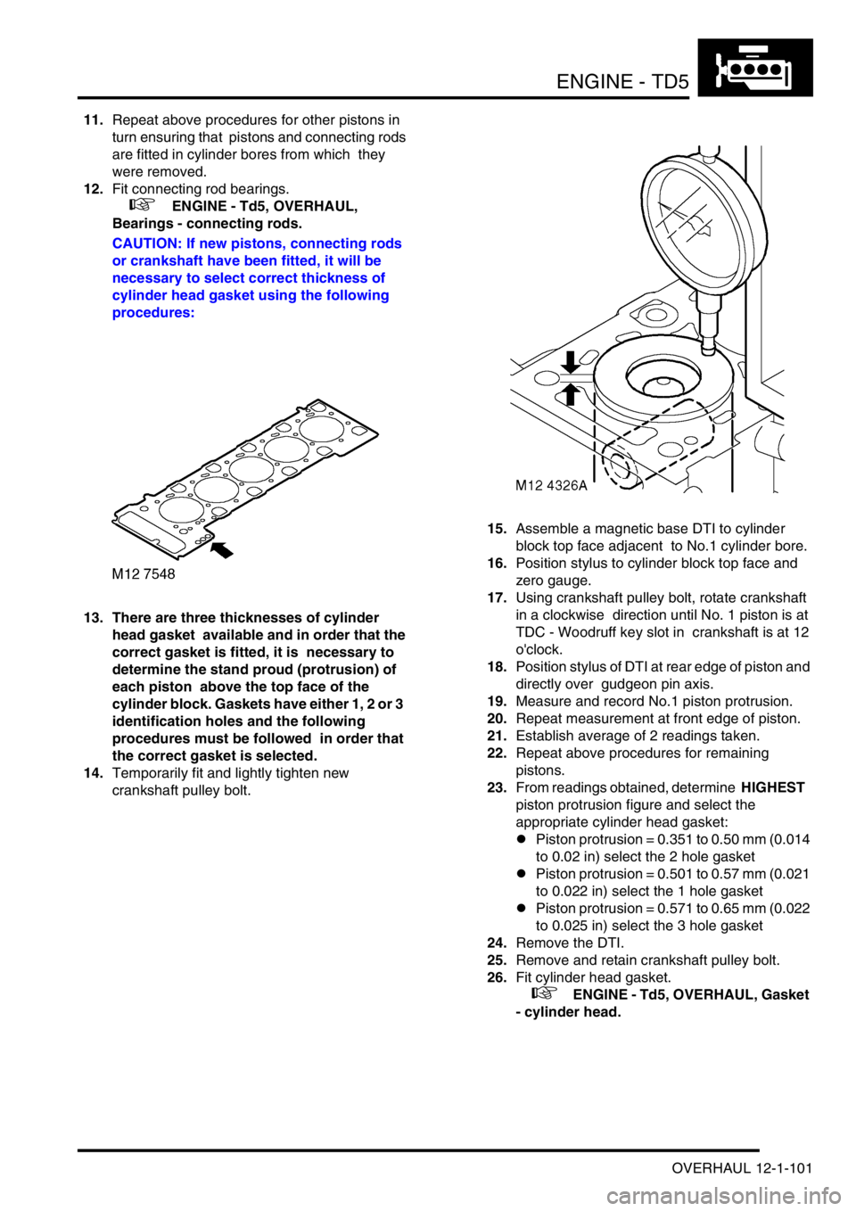
13. There are three thicknesses of cylinder
head gasket available and in order that the
correct gasket is fitted, it is necessary to
determine the stand proud (protrusion) of
each piston above the top face of the
cylinder block. Gaskets have either 1, 2 or 3
identification holes and the following
procedures must be followed in order that
the correct gasket is selected.
14.Temporarily fit and lightly tighten new
crankshaft pulley bolt. 15.Assemble a magnetic base DTI to cylinder
block top face adjacent to No.1 cylinder bore.
16.Position stylus to cylinder block top face and
zero gauge.
17.Using crankshaft pulley bolt, rotate crankshaft
in a clockwise direction until No. 1 piston is at
TDC - Woodruff key slot in crankshaft is at 12
o'clock.
18.Position stylus of DTI at rear edge of piston and
directly over gudgeon pin axis.
19.Measure and record No.1 piston protrusion.
20.Repeat measurement at front edge of piston.
21.Establish average of 2 readings taken.
22.Repeat above procedures for remaining
pistons.
23.From readings obtained, determine HIGHEST
piston protrusion figure and select the
appropriate cylinder head gasket:
lPiston protrusion = 0.351 to 0.50 mm (0.014
to 0.02 in) select the 2 hole gasket
lPiston protrusion = 0.501 to 0.57 mm (0.021
to 0.022 in) select the 1 hole gasket
lPiston protrusion = 0.571 to 0.65 mm (0.022
to 0.025 in) select the 3 hole gasket
24.Remove the DTI.
25.Remove and retain crankshaft pulley bolt.
26.Fit cylinder head gasket.
+ ENGINE - Td5, OVERHAUL, Gasket
- cylinder head.
Page 248 of 1672

ENGINE - V8
DESCRIPTION AND OPERATION 12-2-5
1Core plugs
2Cylinder block
3Camshaft
4Dipstick tube, clamp and bolt
5Woodruff key
6Timing chain
7Camshaft timing gear
8Washer
9Bolt - camshaft timing gear
10Thrust plate - camshaft end-float
11Bolt - camshaft thrust plate
12Gasket - timing cover
13Timing cover
14Oil pressure switch
15Bolt
16Crankshaft front oil seal
17Oil filter element
18Crankshaft front pulley
19Washer
20Bolt - crankshaft front pulley
21Upper main bearing shell
22Upper centre main bearing shell and thrust
washer
23Crankshaft
24Woodruff key
25Crankshaft timing gear
26Lower main bearing shells
27Numbers 1, 2 and 3 main bearing caps
28Bolt - main bearing caps
29Oil pick-up pipe and strainer
30'O' ring31Bolt - oil pick-up pipe
32Gasket - sump
33Sump
34Bolt - sump
35Sump oil drain plug
36Sealing washer
37Spacer, washers and nut - oil pick-up pipe
38Number 4 main bearing cap
39Bolt - connecting rod big-end bearing cap
40Connecting rod big-end bearing shell - lower
41Connecting rod big-end bearing cap
42Number 5 - rear main bearing cap
43Cruciform seal - rear main bearing cap
44Number 5 - rear main bearing shell
45Crankshaft rear oil seal
46Crankshaft knock sensor
47Side bolt - main bearing cap
48Side Allen bolt - main bearing cap
49Dowty washers
50Connecting rod big-end bearing shell - upper
51Connecting rod
52Piston
53Gudgeon pin
54Oil control ring
55Top compression ring
562nd compression ring
57Flywheel/drive plate and starter ring gear
58Bolt - flywheel/drive plate
Page 249 of 1672
ENGINE - V8
12-2-6 DESCRIPTION AND OPERATION
Description
General
The V8 petrol engine is an eight cylinder, water cooled unit having two banks of four cylinders positioned at 90 degrees
to each other. The engine comprises five main castings - two cylinder heads, cylinder block, timing cover and the oil
sump, all of which are manufactured from aluminium alloy.
NAS market vehicles from 03 model year receive a 4.6 litre version of the V8 engine to replace the previous 4.0 litre
version.
Cylinder heads
The cylinder heads are fitted with replaceable valve guides and valve seat inserts with the combustion chambers
formed in the head. Each cylinder head is sealed to the cylinder block with a gasket. The exhaust manifolds are bolted
to the outside of each cylinder head whilst the inlet manifolds are located in the centre of the 'Vee' and are bolted to
the inside face of each head. Inlet and exhaust manifolds are sealed to the cylinder heads by means of gaskets.
Each cylinder has a single inlet and exhaust valve. The exhaust valves are of the 'carbon break' type, a recess on the
valve stem prevents a build-up of carbon in the valve guide by dislodging particles of carbon as the valve stem moves
up and down the guide. Inlet and exhaust valve stem oil seals are fitted at the top of each valve guide. Valve operation
is by means of rocker arms, push rods and hydraulic tappets. Each of the rocker arms is located on a rocker shaft
which is supported by means of pedestals bolted to the cylinder heads. A spring, positioned on either side of each
rocker arm, maintains the correct relative position of the arm to its valve stem. The rocker arms are operated directly
by the push rods which pass through drillings in the cylinder heads and cylinder block. The bottom end of each push
rod locates in a hydraulic tappet operated by the single, chain driven camshaft.
The rocker covers are bolted to the cylinder heads and are sealed to the heads by a rubber gasket. Stub pipes for
crankcase ventilation hose connections are fitted to each rocker cover, the pipe in the right hand cover incorporates
an oil separator. The engine oil filler cap is situated in the right hand cover.
Cylinder block and camshaft
The cylinder block is fitted with cast iron cylinder liners which are shrink fitted and locate on stops in the block. The
camshaft is positioned in the centre of the cylinder block and runs in one piece bearing shells which are line bored
after fitting. Camshaft end-float is controlled by a thrust plate bolted to the front of the cylinder block. A timing gear,
chain driven by the crankshaft timing gear is bolted to the front of the camshaft.
Crankshaft and main bearings
The crankshaft is carried in five main bearings. The upper main bearing shell locations are an integral part of the
cylinder block casting. The lower main bearing caps are bolted to the cylinder block on either side of the upper bearing
shell locations with an additional bolt being inserted into each cap from either side of the cylinder block. The rear
main bearing cap carries the crankshaft rear oil seal and is sealed to the cylinder block by means of cruciform shaped
seals in each side of the cap. Number four main bearing cap carries the stud fixing for the oil pick-up pipe. Lower
main bearing shells are plain whilst the upper shells have an oil feed hole and are grooved. Crankshaft end-float is
controlled by the thrust faces of the upper centre shell. The crankshaft timing gear is located on the front of the
crankshaft by means of a Woodruff key which is also used to drive the gear type oil pump. The flywheel/drive plate
carries the crankshaft position sensor reluctor ring and is dowel located and bolted to the flywheel.
Timing cover
The timing cover is bolted to the front of the cylinder block and is sealed to the block with a gasket. The disposable,
full flow oil filter canister is screwed on to the timing cover which also carries the oil pressure switch, oil pressure relief
valve and crankshaft front oil seal. The gear type oil pump is integral with the cover which also has an internal oilway
to direct oil from the oil cooler to the filter.
NOTE: Oil coolers are only fitted to vehicles up to VIN 756821.
Page 288 of 1672
ENGINE - V8
OVERHAUL 12-2-45
OVERHAUL
Gasket - inlet manifold
$% 30.15.08.01
Disassembly
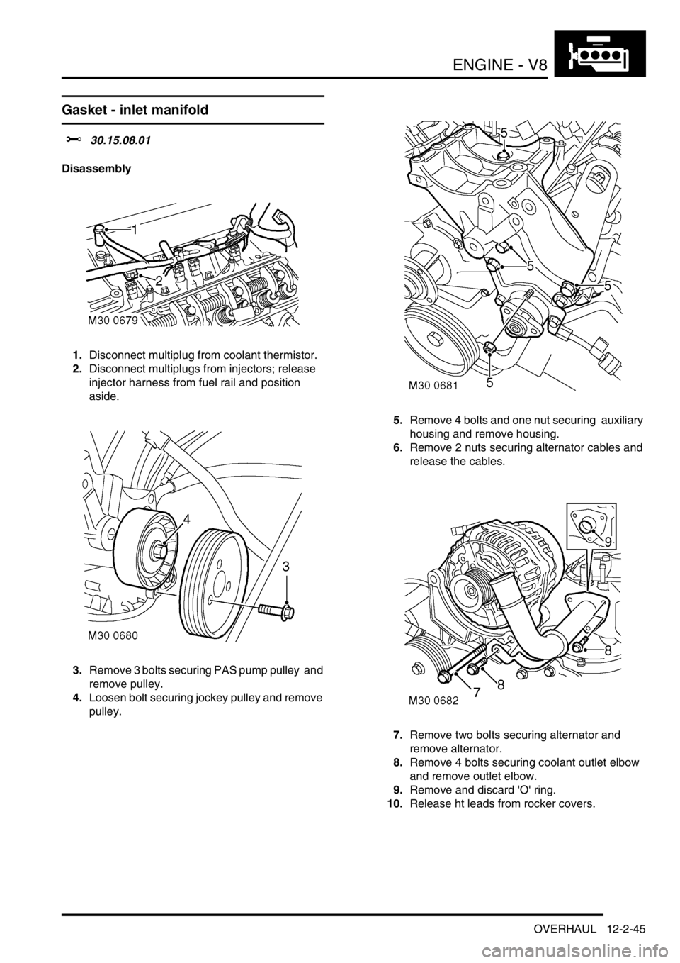
1.Disconnect multiplug from coolant thermistor.
2.Disconnect multiplugs from injectors; release
injector harness from fuel rail and position
aside.
3.Remove 3 bolts securing PAS pump pulley and
remove pulley.
4.Loosen bolt securing jockey pulley and remove
pulley. 5.Remove 4 bolts and one nut securing auxiliary
housing and remove housing.
6.Remove 2 nuts securing alternator cables and
release the cables.
7.Remove two bolts securing alternator and
remove alternator.
8.Remove 4 bolts securing coolant outlet elbow
and remove outlet elbow.
9.Remove and discard 'O' ring.
10.Release ht leads from rocker covers.
Page 291 of 1672
ENGINE - V8
12-2-48 OVERHAUL
10.Clean mating faces of rocker covers and
cylinder heads.
11.Fit new rocker cover gaskets, dry, position
rocker cover, fit bolts and working in diagonal
sequence, tighten to:
lStage 1 - 3 Nm (2.5 lbf.ft)
lStage 2 - 8 Nm (6 lbf.ft)
12.Ensure that outer rim of gasket is correctly
positioned around periphery of rocker cover.
13.Secure ht leads to rocker cover.
14.Clean coolant outlet elbow mating faces.
15.Lubricate and fit new 'O' ring to outlet pipe.
16.Position coolant outlet elbow, fit bolts and
tighten to 22 Nm (17 lbf.ft).
17.Position alternator, fit mounting bolts and
tighten to 45 Nm (34 lbf.ft).
18.Position alternator cables and tighten terminal
B+ to 18 Nm (13 lbf.ft) and terminal D+ to 5 Nm
(3.5 lbf.ft).
19.Position auxiliary housing, fit bolts and tighten
to 40 Nm (30 lbf.ft). Fit nut and tighten to 22 Nm
(17 lbf.ft).
20.Clean jockey pulley mating faces.
21.Position jockey pulley and tighten bolt to 50 Nm
(37 lbf.ft).
22.Clean PAS pump pulley mating faces.
23.Position PAS pump pulley, fit bolts and tighten
to 22 Nm (17 lbf.ft).
24.Secure injector harness and connect injector
multiplugs.
25.Connect multiplug to coolant thermistor.
Gasket - exhaust manifold
$% 30.15.12.01
Disassembly
1.Remove 8 bolts securing exhaust manifold and
collect spacers. Discard the bolts.
2.Remove exhaust manifold.
3.Remove 2 manifold gaskets and discard.
Reassembly
1.Clean exhaust manifold and cylinder head
mating face.
CAUTION: Do not use a metal scraper or
machined surfaces may be damaged.
2.Fit new gaskets, dry, fit exhaust manifold.
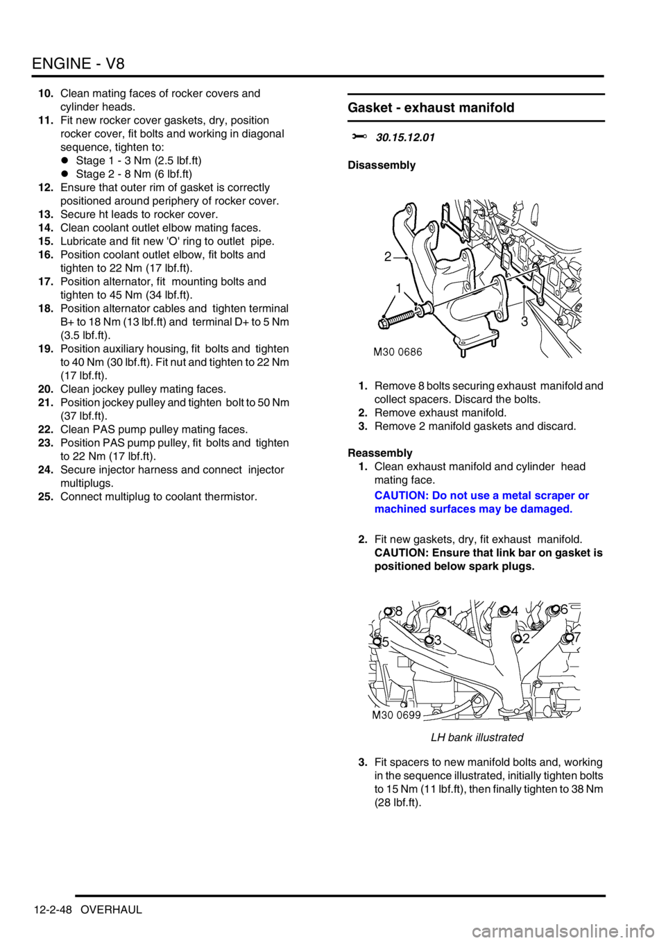
CAUTION: Ensure that link bar on gasket is
positioned below spark plugs.
LH bank illustrated
3.Fit spacers to new manifold bolts and, working
in the sequence illustrated, initially tighten bolts
to 15 Nm (11 lbf.ft), then finally tighten to 38 Nm
(28 lbf.ft).
Page 299 of 1672
ENGINE - V8
12-2-56 OVERHAUL
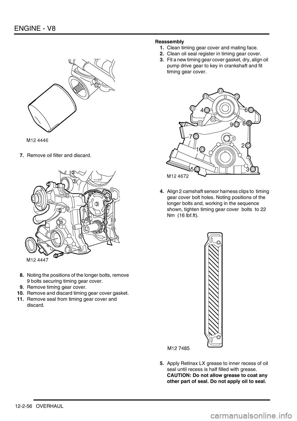
7.Remove oil filter and discard.
8.Noting the positions of the longer bolts, remove
9 bolts securing timing gear cover.
9.Remove timing gear cover.
10.Remove and discard timing gear cover gasket.
11.Remove seal from timing gear cover and
discard. Reassembly
1.Clean timing gear cover and mating face.
2.Clean oil seal register in timing gear cover.
3.Fit a new timing gear cover gasket, dry, align oil
pump drive gear to key in crankshaft and fit
timing gear cover.
4.Align 2 camshaft sensor harness clips to timing
gear cover bolt holes. Noting positions of the
longer bolts and, working in the sequence
shown, tighten timing gear cover bolts to 22
Nm (16 lbf.ft).
5.Apply Retinax LX grease to inner recess of oil
seal until recess is half filled with grease.
CAUTION: Do not allow grease to coat any
other part of seal. Do not apply oil to seal.
Page 301 of 1672
ENGINE - V8
12-2-58 OVERHAUL
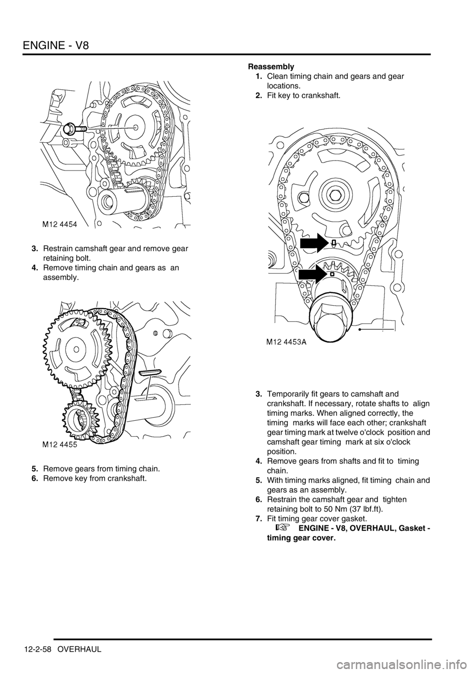
3.Restrain camshaft gear and remove gear
retaining bolt.
4.Remove timing chain and gears as an
assembly.
5.Remove gears from timing chain.
6.Remove key from crankshaft. Reassembly
1.Clean timing chain and gears and gear
locations.
2.Fit key to crankshaft.
3.Temporarily fit gears to camshaft and
crankshaft. If necessary, rotate shafts to align
timing marks. When aligned correctly, the
timing marks will face each other; crankshaft
gear timing mark at twelve o'clock position and
camshaft gear timing mark at six o'clock
position.
4.Remove gears from shafts and fit to timing
chain.
5.With timing marks aligned, fit timing chain and
gears as an assembly.
6.Restrain the camshaft gear and tighten
retaining bolt to 50 Nm (37 lbf.ft).
7.Fit timing gear cover gasket.
+ ENGINE - V8, OVERHAUL, Gasket -
timing gear cover.
Page 316 of 1672
ENGINE - V8
OVERHAUL 12-2-73
6.Reference mark main bearing caps to aid
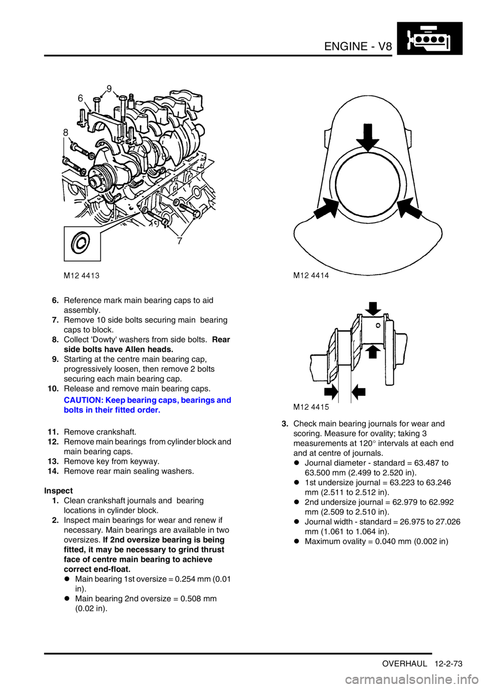
assembly.
7.Remove 10 side bolts securing main bearing
caps to block.
8.Collect 'Dowty' washers from side bolts. Rear
side bolts have Allen heads.
9.Starting at the centre main bearing cap,
progressively loosen, then remove 2 bolts
securing each main bearing cap.
10.Release and remove main bearing caps.
CAUTION: Keep bearing caps, bearings and
bolts in their fitted order.
11.Remove crankshaft.
12.Remove main bearings from cylinder block and
main bearing caps.
13.Remove key from keyway.
14.Remove rear main sealing washers.
Inspect
1.Clean crankshaft journals and bearing
locations in cylinder block.
2.Inspect main bearings for wear and renew if
necessary. Main bearings are available in two
oversizes. If 2nd oversize bearing is being
fitted, it may be necessary to grind thrust
face of centre main bearing to achieve
correct end-float.
lMain bearing 1st oversize = 0.254 mm (0.01
in).
lMain bearing 2nd oversize = 0.508 mm
(0.02 in).3.Check main bearing journals for wear and
scoring. Measure for ovality; taking 3
measurements at 120
° intervals at each end
and at centre of journals.
lJournal diameter - standard = 63.487 to
63.500 mm (2.499 to 2.520 in).
l1st undersize journal = 63.223 to 63.246
mm (2.511 to 2.512 in).
l2nd undersize journal = 62.979 to 62.992
mm (2.509 to 2.510 in).
lJournal width - standard = 26.975 to 27.026
mm (1.061 to 1.064 in).
lMaximum ovality = 0.040 mm (0.002 in)
Page 317 of 1672
ENGINE - V8
12-2-74 OVERHAUL
Reassembly
1.Clean main bearing locations in cylinder block
and bearing caps.
2.Clean sealant from rear main bearing cap and
mating faces.
3.Fit key to keyway.
4.Check threads of main bearing cap bolts for
damage, renew bolts in pairs.
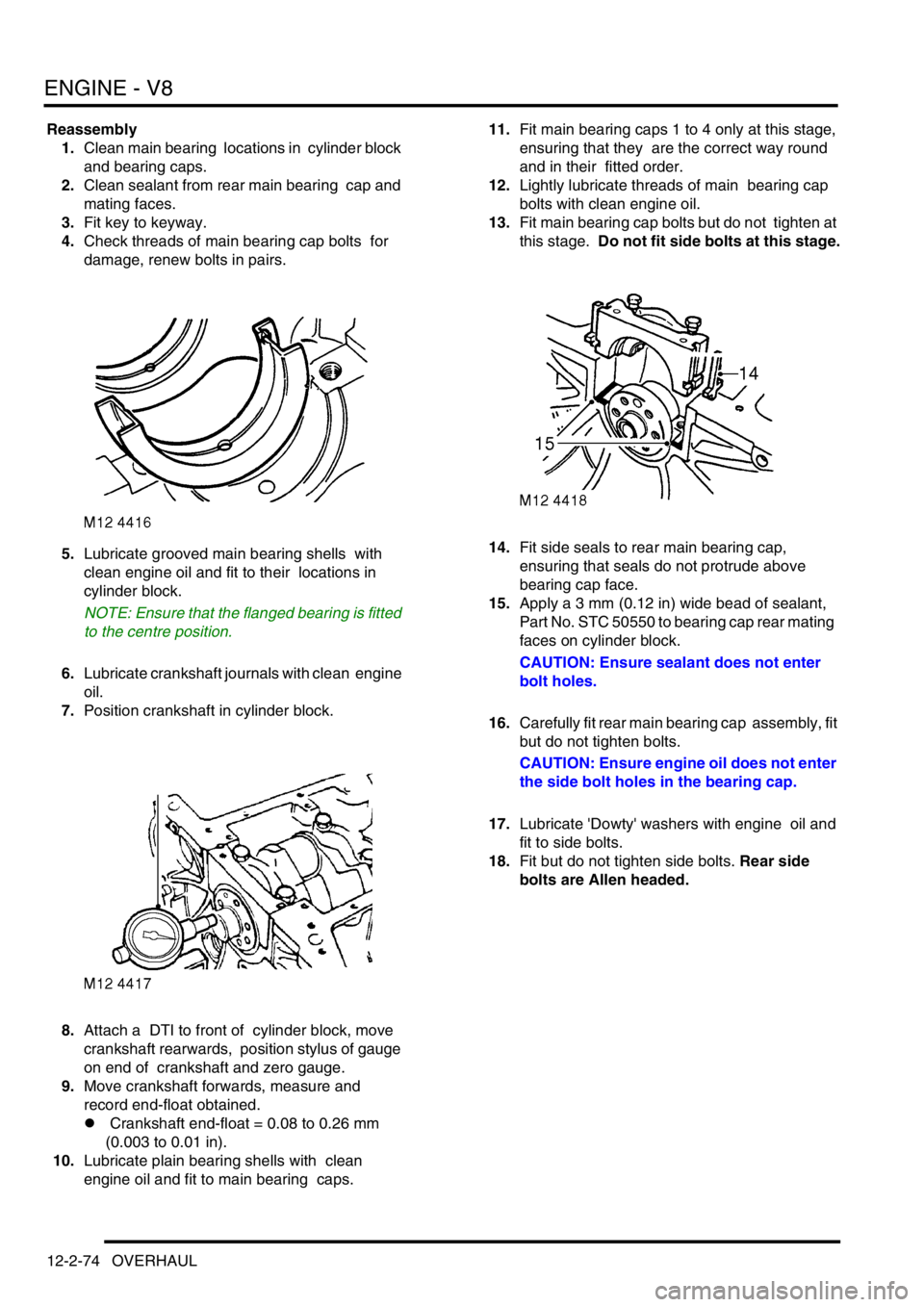
5.Lubricate grooved main bearing shells with
clean engine oil and fit to their locations in
cylinder block.
NOTE: Ensure that the flanged bearing is fitted
to the centre position.
6.Lubricate crankshaft journals with clean engine
oil.
7.Position crankshaft in cylinder block.
8.Attach a DTI to front of cylinder block, move
crankshaft rearwards, position stylus of gauge
on end of crankshaft and zero gauge.
9.Move crankshaft forwards, measure and
record end-float obtained.
l Crankshaft end-float = 0.08 to 0.26 mm
(0.003 to 0.01 in).
10.Lubricate plain bearing shells with clean
engine oil and fit to main bearing caps. 11.Fit main bearing caps 1 to 4 only at this stage,
ensuring that they are the correct way round
and in their fitted order.
12.Lightly lubricate threads of main bearing cap
bolts with clean engine oil.
13.Fit main bearing cap bolts but do not tighten at
this stage. Do not fit side bolts at this stage.
14.Fit side seals to rear main bearing cap,
ensuring that seals do not protrude above
bearing cap face.
15.Apply a 3 mm (0.12 in) wide bead of sealant,
Part No. STC 50550 to bearing cap rear mating
faces on cylinder block.
CAUTION: Ensure sealant does not enter
bolt holes.
16.Carefully fit rear main bearing cap assembly, fit
but do not tighten bolts.
CAUTION: Ensure engine oil does not enter
the side bolt holes in the bearing cap.
17.Lubricate 'Dowty' washers with engine oil and
fit to side bolts.
18.Fit but do not tighten side bolts. Rear side
bolts are Allen headed.
Page 456 of 1672
ENGINE MANAGEMENT SYSTEM - TD5
REPAIRS 18-1-63
Switch - cruise control (set/resume)
$% 19.75.33
Remove
1.Remove the key from the starter switch.
Disconnect both battery leads, negative lead
first. Wait ten minutes before starting work.
2.Remove driver's airbag module.
+ RESTRAINT SYSTEMS, REPAIRS,
Airbag module - drivers.
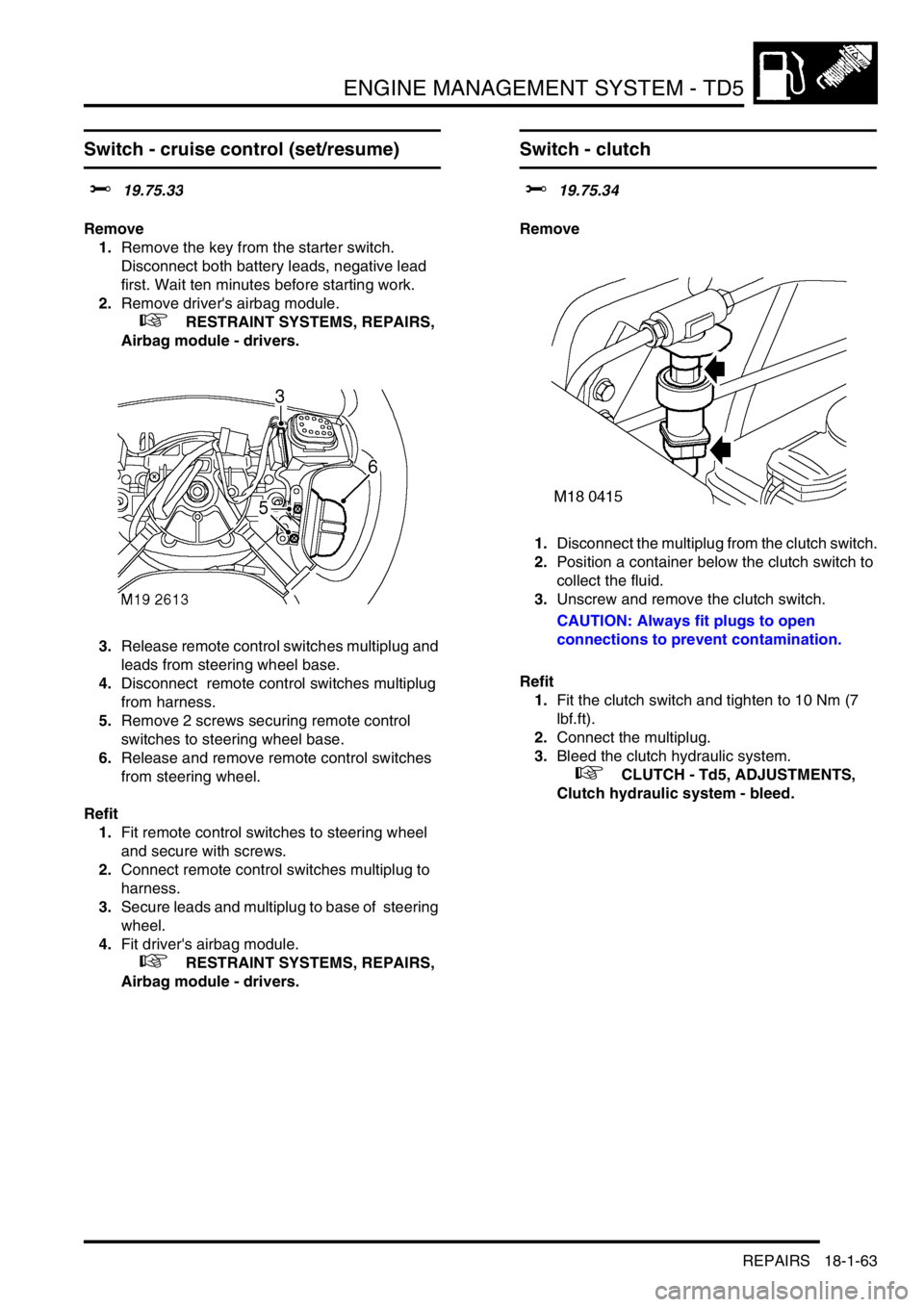
3.Release remote control switches multiplug and
leads from steering wheel base.
4.Disconnect remote control switches multiplug
from harness.
5.Remove 2 screws securing remote control
switches to steering wheel base.
6.Release and remove remote control switches
from steering wheel.
Refit
1.Fit remote control switches to steering wheel
and secure with screws.
2.Connect remote control switches multiplug to
harness.
3.Secure leads and multiplug to base of steering
wheel.
4.Fit driver's airbag module.
+ RESTRAINT SYSTEMS, REPAIRS,
Airbag module - drivers.
Switch - clutch
$% 19.75.34
Remove
1.Disconnect the multiplug from the clutch switch.
2.Position a container below the clutch switch to
collect the fluid.
3.Unscrew and remove the clutch switch.
CAUTION: Always fit plugs to open
connections to prevent contamination.
Refit
1.Fit the clutch switch and tighten to 10 Nm (7
lbf.ft).
2.Connect the multiplug.
3.Bleed the clutch hydraulic system.
+ CLUTCH - Td5, ADJUSTMENTS,
Clutch hydraulic system - bleed.