LAND ROVER FRELANDER 2 2006 Repair Manual
Manufacturer: LAND ROVER, Model Year: 2006, Model line: FRELANDER 2, Model: LAND ROVER FRELANDER 2 2006Pages: 3229, PDF Size: 78.5 MB
Page 601 of 3229
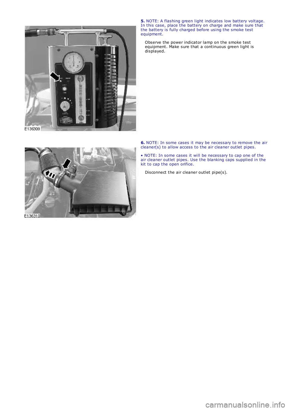
5. NOTE: A flas hing green l ight indi cat es low bat tery volt age.In t hi s case, place t he batt ery on charge and make s ure t hatt he batt ery i s ful ly charged before us ing t he s moke tes tequipment.
Obs erve the power indicat or l amp on t he s moke t es tequipment . Make s ure t hat a cont inuous green l ight isdi s pl ayed.
6. NOTE: In some cas es i t may be neces s ary t o remove the ai rcleaner(s) t o al low acces s t o t he air cleaner out let pi pes .
• NOTE: In s ome cas es it wi ll be neces s ary t o cap one of t heair cleaner out let pi pes . Us e t he blanking caps suppli ed in thekit t o cap t he open orifice.
Dis connect t he air cl eaner outl et pi pe(s ).
Page 602 of 3229
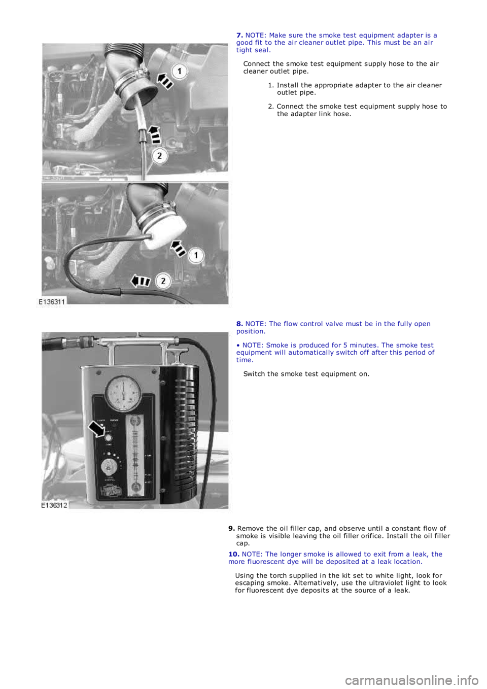
7. NOTE: Make s ure t he s moke tes t equipment adapt er is agood fi t t o the ai r cleaner out let pipe. Thi s mus t be an ai rt ight s eal .
Connect the s moke t est equipment s uppl y hos e to the ai rcl eaner outl et pi pe.
1. Ins tall t he appropri at e adapter t o t he air cleanerout let pi pe.
2. Connect t he s moke t es t equipment s uppl y hose tothe adapter l ink hos e.
8. NOTE: The fl ow cont rol valve mus t be i n t he ful ly openpos it ion.
• NOTE: Smoke i s produced for 5 mi nutes . The smoke tes tequipment wil l aut omati cal ly s wi tch off aft er t his period oft ime.
Swi tch t he s moke t est equipment on.
9. Remove the oi l fil ler cap, and obs erve unti l a cons t ant flow ofs moke is vi s ible leavi ng t he oil fi ll er orifice. Ins tal l the oi l fil lercap.
10. NOTE: The l onger s moke is allowed t o exit from a l eak, t hemore fl uorescent dye wil l be depos it ed at a l eak locat ion.
Us ing the t orch s uppl ied i n t he kit s et to whit e li ght, l ook fores capi ng smoke. Alt ernat ively, use the ul travi olet li ght to l ookfor fluores cent dye depos it s at the source of a leak.
Page 603 of 3229
Publi s hed: 23-Aug-2011
Engine - I6 3.2L Petrol -
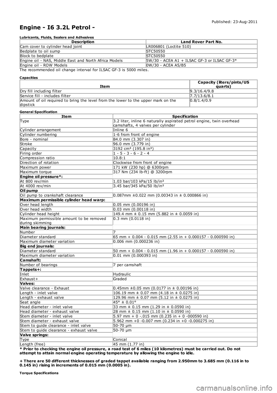
Lubricants, Fluids, Sealers and AdhesivesDescriptionLand Rover Part No.
Cam cover to cyli nder head jointLR006801 (Loct it e 510)
Bedplate to oi l s umpSTC50550Block t o bedpl ateSTC50550
Engine oil - NAS, Mi ddl e Eas t and Nort h Africa Models5W /30 - ACEA A1 + ILSAC GF-3 or ILSAC GF-3*
Engine oil - ROW Models0W /30 - ACEA A5/B5The recommended oil change i nterval for ILSAC GF-3 is 5000 mi les .
C apacities
ItemCapacity (liters/pints/USquarts)
Dry fi ll i ncludi ng fi lt er9.3/16.4/9.8
Service fil l - includes fi lt er7.7/13.6/8.1Amount of oil required t o bri ng the level from the lower to the upper mark on thedips t ick0.8/1.4/0.9
General Specification
ItemSpecificationType3.2 li ter, inli ne 6 nat urall y aspi rat ed pet rol engine, twi n overheadcams haft s, 4 val ves per cylinderCyli nder arrangementInli ne 6
Cyli nder numberi ng1-6 from front of engine
Bore - nominal84.0 mm (3.307 in)St roke96.0 mm (3.779 in)
Capaci ty3192 cm³ (195.8 i n³)
Firing order1 - 5 - 3 - 6 - 2 - 4Compres s ion rati o10.8:1
Di recti on of rotat ionCl ockwis e from front of engi ne
Maximum power171 kW (230 hp) @ 6300rpmMaximum t orque317 Nm (234 lb-ft ) @ 3200rpm
Engine oil pressure*:
At 800 rev/min1.03 bar/103 kPa/15 lb/in²At 4000 rev/min3.45 bar/345 kPa/50 lb/in²
Oil pump
Oi l pump to cranks haft clearance0.087mm ±0.022 mm (0.00343 i n ± 0.000866 i n)Maximum permissible cylinder head w arp:
Over head length0.05 mm (0.00196 i n)
Over head widt h0.03 mm (0.00118 i n)Cyli nder head height149.4 mm ± 0.15 mm (5.882 in ± 0.0059 i n)
Maximum permi s si ble amount t o be removedduri ng s ki mmi ng0.3 mm (0.0118 in)
Main bearing journals:
Number7
Di amet er s tandard65 mm + 0.004 - 0.015 mm (2.55 in + 0.000157 - 0.000590 in)Maximum diamet er variat ion0.006 mm (0.000236 in)
Big end journals:
Di amet er s tandard50 mm + 0.004 - 0.015 mm (1.96 in + 0.000157 - 0.000590 in)Maximum diamet er variat ion0.01 mm (0.000393 i n)
Camshaft:
Number of bearings7 per cams haftT appets+:
InletHydrauli c
Exhaus t +GradedValves:
Valve clearance - Exhaus t0.45mm ±0.05 mm (0.0177 in ± 0.00196 in)
Lengt h - i nlet valve106.19 mm ± 0.07 mm (4.18 in ± 0.0275 i n)Lengt h - exhaus t valve129.96 mm ± 0.07 mm (5.12 in ± 0.0275 i n)
Seat angl e45° ± 0.01°
Head diamet er - inlet valve33 mm ± 0.15 mm (1.29 in ± 0.0590 i n)Head diamet er - exhaus t val ve28 mm ± 0.15 mm (1.10 in ± 0.0590 i n)
St em diamet er - inlet valve5.97 mm + 0 -.015 mm (0.235 in + 0 -000590 i n)
St em diamet er - exhaus t val ve5.962 mm +0 -0.007 mm (0.234 in +0 -0.000275 i n)St em t o guide clearance - i nlet val ve50-70 µm
St em t o guide clearance - exhaus t valve50-70 µm
Valve springs:TypeConical
Lengt h (free)45 mm (1.77 in)
* Prior to checking the engine oil pressure, a road test of 6 miles (10 kilometres) must be carried out. Do notattempt to attain normal engine operating temperature by allowing the engine to idle.
+ T here are 50 different thicknesses of graded tappet available ranging from 2.950mm to 3.685 mm (0.116 in to0.145 in) rising in increments of 0.015 mm (0.0005 in).
Torque Specifications
Page 604 of 3229
DescriptionNmlb-ft
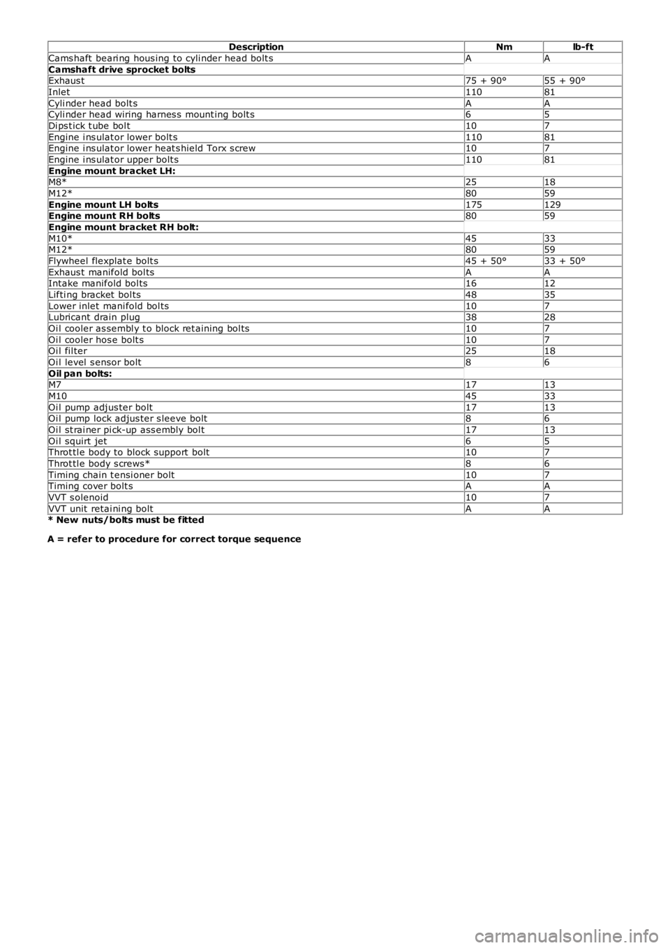
Cams haft beari ng hous ing to cyli nder head bolt sAA
Camshaft drive sprocket boltsExhaus t75 + 90°55 + 90°
Inlet11081
Cyli nder head bolt sAACyli nder head wiring harnes s mount ing bolt s65
Di ps t ick t ube bol t107
Engine i ns ulat or lower bolt s11081Engine i ns ulat or lower heat s hield Torx s crew107
Engine i ns ulat or upper bolt s11081
Engine mount bracket LH:M8*2518
M12*8059
Engine mount LH bolts175129Engine mount RH bolts8059
Engine mount bracket RH bolt:
M10*4533M12*8059
Flywheel flexplat e bolt s45 + 50°33 + 50°
Exhaus t manifold bol tsAAIntake manifold bol ts1612
Lifti ng bracket bol ts4835
Lower inlet mani fold bol ts107Lubricant drain plug3828
Oi l cooler as sembl y t o block ret aining bol ts107
Oi l cooler hos e bolt s107Oi l fil ter2518
Oi l level s ensor bolt86
Oil pan bolts:M71713
M104533
Oi l pump adjus ter bolt1713Oi l pump lock adjus ter s leeve bolt86
Oi l st rai ner pi ck-up ass embly bol t1713
Oi l squirt jet65Throt tl e body to block support bolt107
Throt tl e body s crews*86
Timing chain t ensi oner bolt107Timing cover bolt sAA
VVT s olenoid107
VVT unit retai ni ng boltAA* New nuts/bolts must be fitted
A = refer to procedure for correct torque sequence
Page 605 of 3229
Published: 11-May-2011
Engine - I6 3.2L Petrol - Engine
Descript ion and O peration
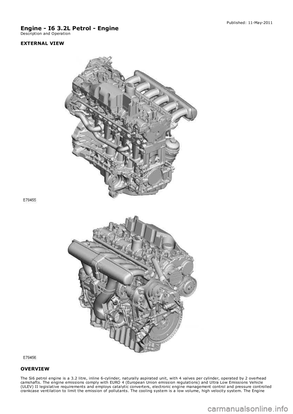
EXTERNAL VIEW OVERVIEW
The Si6 pet rol engine is a 3.2 litre, inline 6-cylinder, nat urally as pirat ed unit, w it h 4 valves per cylinder, operated by 2 overhead
cams haft s. The engine emis sions comply with EURO 4 (European Union emiss ion regulati ons ) and Ultra Low Emiss ions Vehicle
(ULEV) II legis lat ive requirement s and employs catalyt ic convert ers , elect ronic engi ne management control and pres sure cont rolled
crankcas e vent ilat ion to limit t he emiss ion of pollut ant s . The cooling s yst em is a l ow volume, high velocit y s yst em. The Engine
Page 606 of 3229
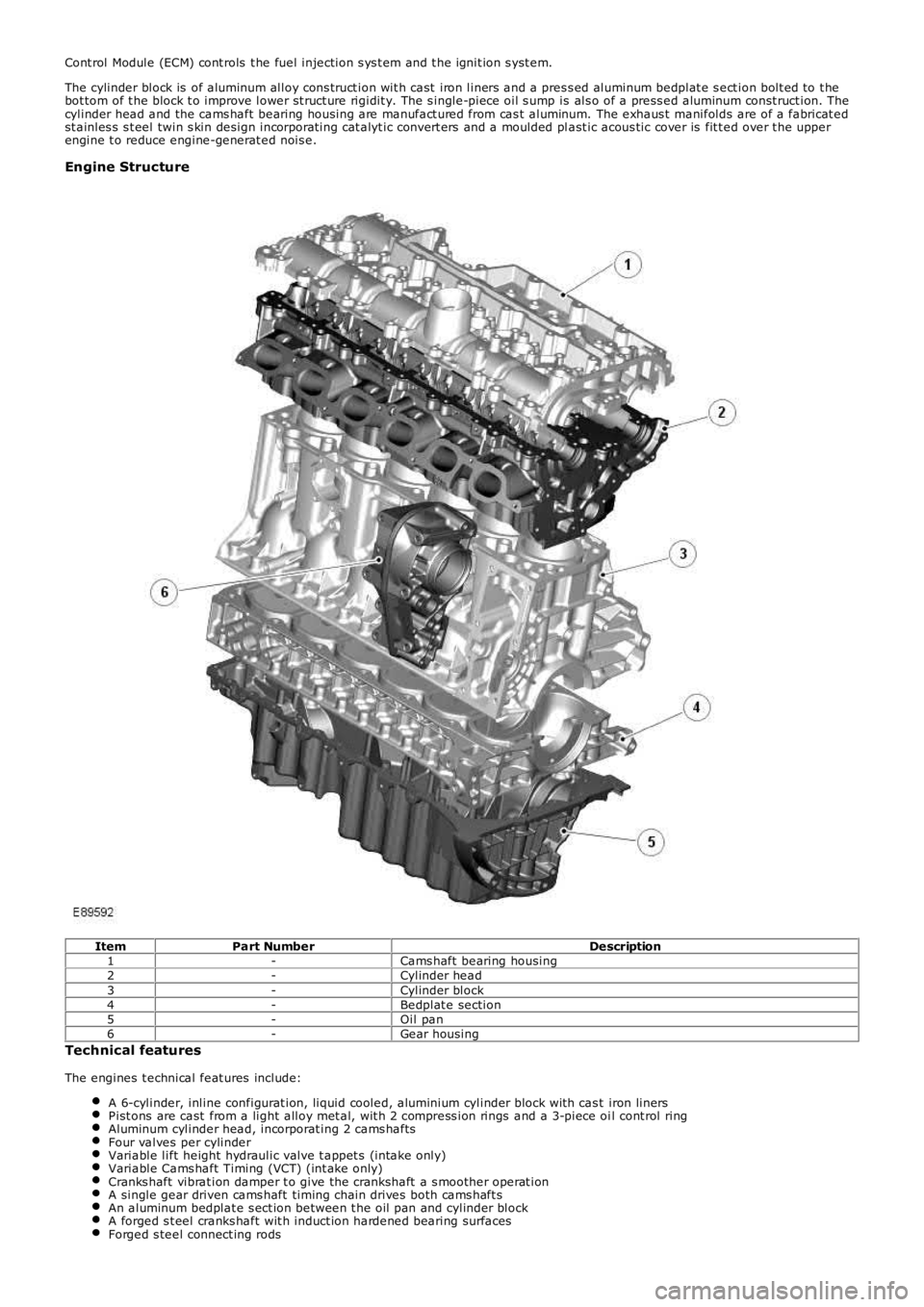
Cont rol Module (ECM) cont rols t he fuel injection s ys t em and t he ignit ion s yst em.
The cylinder block is of aluminum alloy cons truct ion wit h cast iron liners and a pres s ed aluminum bedplat e s ect ion bolt ed to t hebot tom of t he block t o improve lower st ruct ure rigidit y. The s ingle-piece oil s ump is als o of a press ed aluminum const ruct ion. Thecylinder head and the cams haft bearing housing are manufact ured from cas t aluminum. The exhaus t manifolds are of a fabricat edst ainles s s t eel twin s kin design incorporat ing cat alyt ic convert ers and a moulded plast ic acous tic cover is fit t ed over t he upperengine t o reduce engine-generat ed nois e.
Engine Structure
ItemPart NumberDescription1-Cams haft bearing housing2-Cylinder head3-Cylinder block4-Bedplat e section5-Oil pan6-Gear housing
Technical features
The engines t echnical feat ures include:
A 6-cylinder, inline configurat ion, liquid cooled, aluminium cylinder block wit h cast iron linersPist ons are cast from a light alloy met al, wit h 2 compress ion rings and a 3-piece oil cont rol ringAluminum cylinder head, incorporat ing 2 cams haftsFour valves per cylinderVariable lift height hydraulic valve t appet s (intake only)Variable Cams haft Timing (VCT) (int ake only)Cranks haft vibrat ion damper t o give the crankshaft a s moother operat ionA single gear driven cams haft timing chain drives both cams haft sAn aluminum bedplat e s ect ion between t he oil pan and cylinder blockA forged s t eel cranks haft wit h induct ion hardened bearing surfacesForged s teel connect ing rods
Page 607 of 3229
A Rear End Ancillary Drive (READ) s yst emTwo fabricated s t ainles s s t eel t win s kin exhaust manifoldsA 3-pos ition Variable Intake Sys t em (VIS)An advanced Engine Management Syst em (EMS) incorporat ing elect ronic t hrot tle controlFour cat alyt ic converters
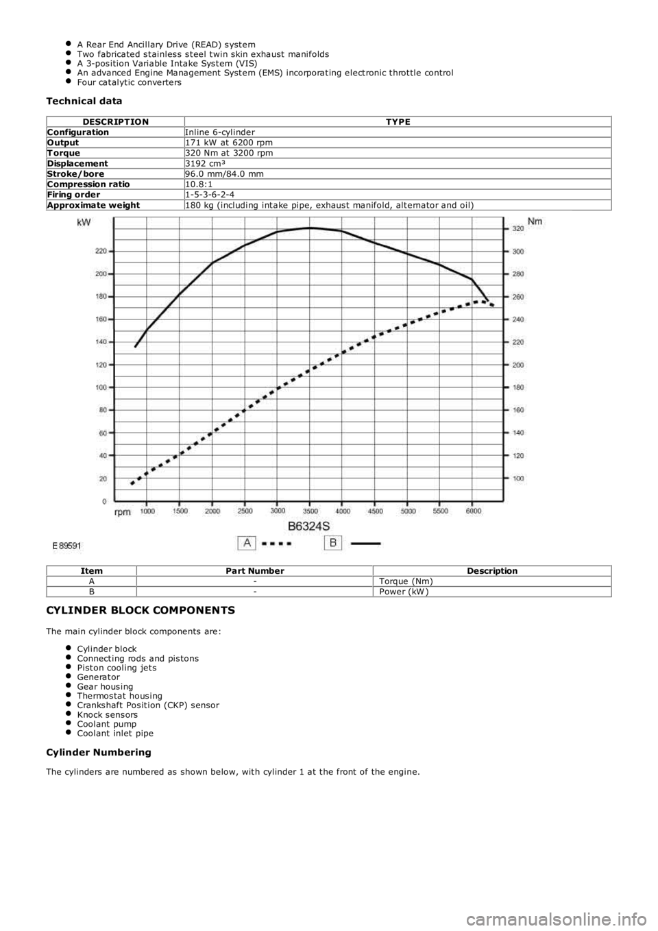
Technical data
DESCR IPT IO NT YPEConfigurationInline 6-cylinderO utput171 kW at 6200 rpmT orque320 Nm at 3200 rpmDisplacement3192 cm³Stroke/bore96.0 mm/84.0 mmCompression ratio10.8:1Firing order1-5-3-6-2-4Approximate weight180 kg (including int ake pipe, exhaus t manifold, alt ernator and oil)
ItemPart NumberDescriptionA-Torque (Nm)B-Power (kW )
CYLINDER BLOCK COMPONENTS
The main cylinder block components are:
Cylinder blockConnect ing rods and pis tonsPist on cooling jet sGenerat orGear hous ingThermos tat hous ingCranks haft Pos it ion (CKP) s ensorKnock s ens orsCoolant pumpCoolant inlet pipe
Cylinder Numbering
The cylinders are numbered as shown below, wit h cylinder 1 at t he front of the engine.
Page 608 of 3229
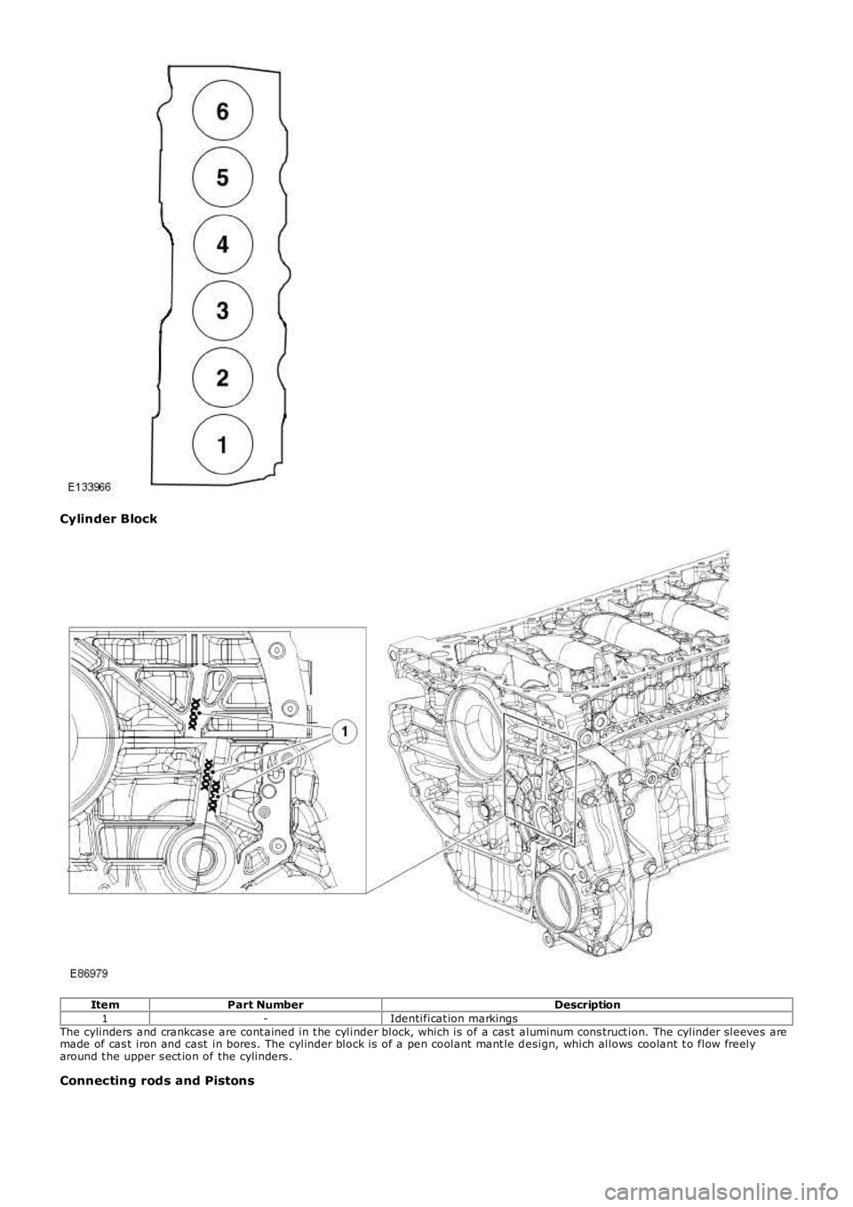
Cylinder Block
ItemPart NumberDescription1-Identificat ion markingsThe cylinders and crankcas e are cont ained in t he cylinder block, which is of a cas t aluminum cons truct ion. The cylinder sleeves aremade of cas t iron and cast in bores. The cylinder block is of a pen coolant mant le design, which allows coolant t o flow freelyaround t he upper s ect ion of the cylinders .
Connecting rods and Pistons
Page 609 of 3229
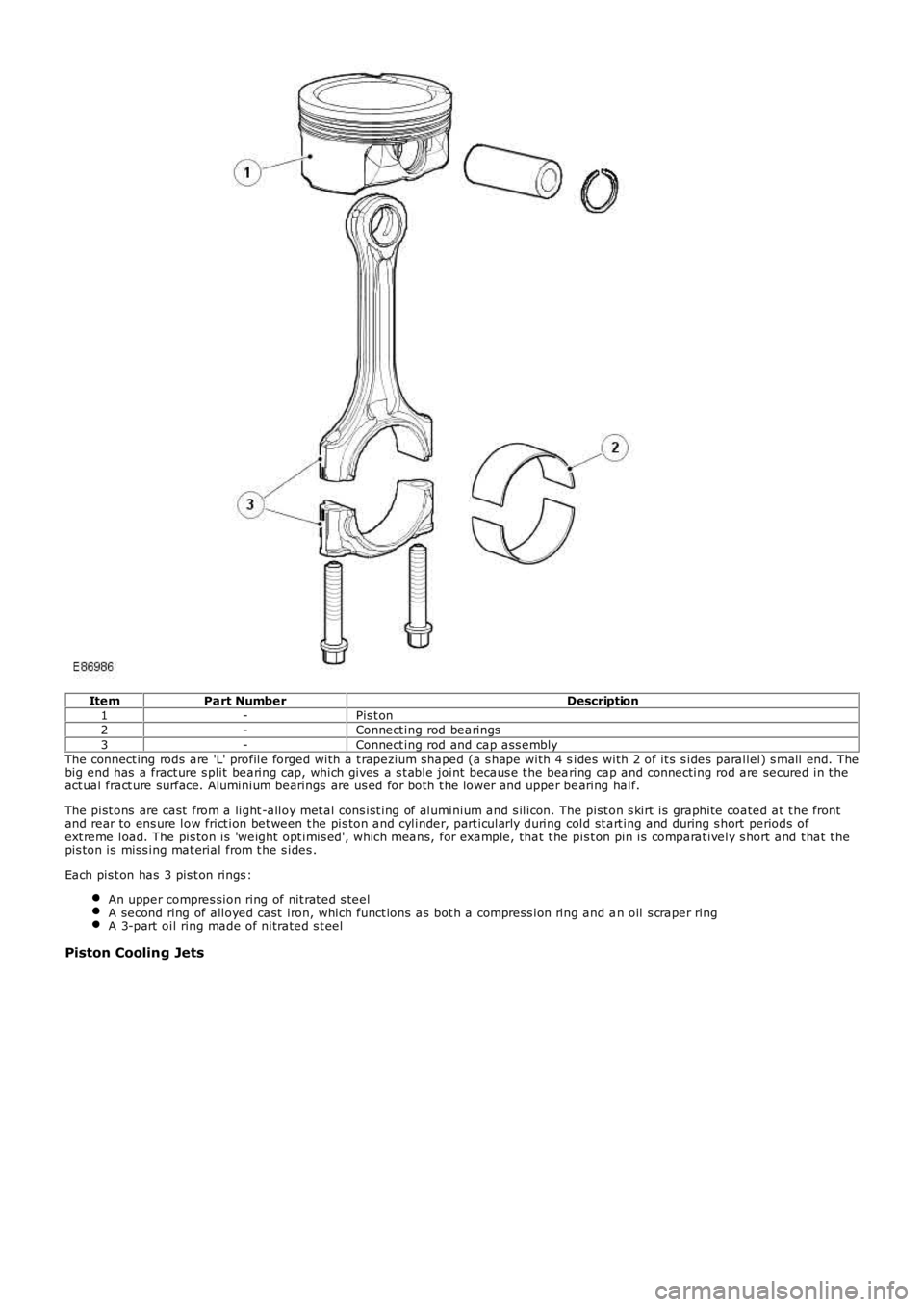
ItemPart NumberDescription1-Pis t on2-Connect ing rod bearings3-Connect ing rod and cap ass emblyThe connect ing rods are 'L' profile forged with a t rapezium shaped (a s hape with 4 sides with 2 of it s s ides parallel) s mall end. Thebig end has a fract ure s plit bearing cap, which gives a s t able joint becaus e t he bearing cap and connecting rod are secured in t heact ual fract ure surface. Aluminium bearings are us ed for both t he lower and upper bearing half.
The pist ons are cast from a light -alloy met al cons ist ing of aluminium and s ilicon. The pist on s kirt is graphite coated at t he frontand rear to ens ure low frict ion bet ween t he pis ton and cylinder, part icularly during cold st art ing and during s hort periods ofext reme load. The pis ton is 'weight opt imis ed', which means, for example, that t he pis t on pin is comparat ively s hort and t hat t hepis ton is miss ing mat erial from t he s ides .
Each pis t on has 3 pis t on rings :
An upper compres sion ring of nit rat ed s teelA second ring of alloyed cast iron, which funct ions as bot h a compress ion ring and an oil s craper ringA 3-part oil ring made of nitrated s t eel
Piston Cooling Jets
Page 610 of 3229
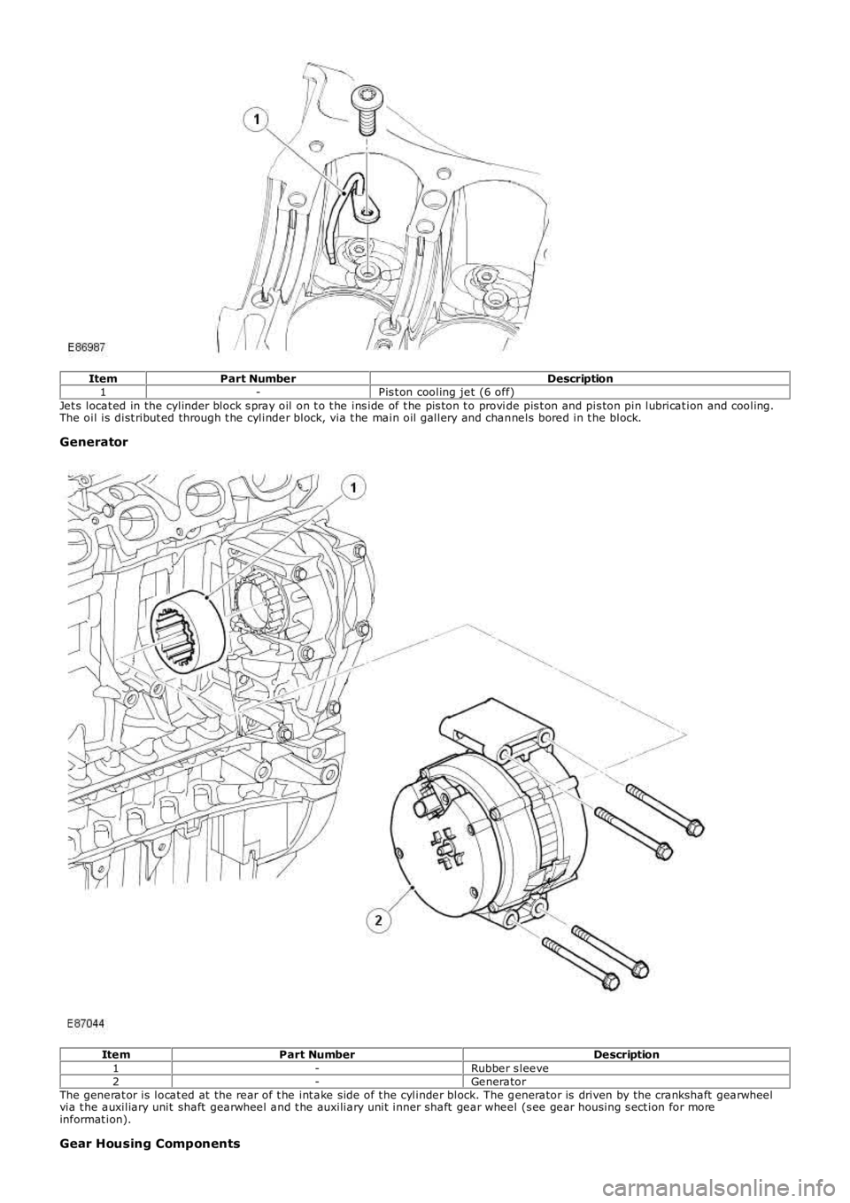
ItemPart NumberDescription1-Pis t on cooling jet (6 off)Jet s locat ed in the cylinder block s pray oil on t o t he ins ide of t he pis ton t o provide pis t on and pis ton pin lubricat ion and cooling.The oil is dist ribut ed through t he cylinder block, via t he main oil gallery and channels bored in t he block.
Generator
ItemPart NumberDescription1-Rubber s leeve2-GeneratorThe generat or is locat ed at the rear of t he int ake side of t he cylinder block. The generator is driven by the crankshaft gearwheelvia t he auxiliary unit shaft gearwheel and t he auxiliary unit inner shaft gear wheel (s ee gear housing s ect ion for moreinformat ion).
Gear Housing Components