stop start LEXUS RCF 2021 Owner's Manual
[x] Cancel search | Manufacturer: LEXUS, Model Year: 2021, Model line: RCF, Model: LEXUS RCF 2021Pages: 408, PDF Size: 8.25 MB
Page 134 of 408
1344-2. Driving procedures
ton is pressed.
■Driving mode
P.192
To drive using temporary shift range
selection, operate the “-” or “+” paddle
shift switch.
When the “-” paddle shift switch is
operated, the shift range will be down-
shifted to a range that enables engine
braking force that is suitable to driving
conditions. When the “+” paddle shift
switch is operated, the shift range will
be one gear higher than the gear in use
during normal D position driving.
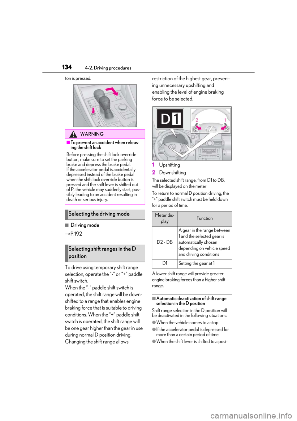
Changing the shift range allows restriction of the highest gear, prevent-
ing unnecessary upshifting and
enabling the level of engine braking
force to be selected.
1
Upshifting
2 Downshifting
The selected shift rang e, from D1 to D8,
will be displayed on the meter.
To return to normal D position driving, the
“+” paddle shift switch must be held down
for a period of time.
A lower shift range will provide greater
engine braking forces than a higher shift
range.
■Automatic deactivation of shift range
selection in the D position
Shift range selection in the D position will
be deactivated in the following situations:
●When the vehicle comes to a stop
●If the accelerator pe dal is depressed for
more than a certai n period of time
●When the shift lever is shifted to a posi-
WARNING
■To prevent an accident when releas-
ing the shift lock
Before pressing the shift lock override
button, make sure to set the parking
brake and depress the brake pedal.
If the accelerator pe dal is accidentally
depressed instead of the brake pedal
when the shift lock override button is
pressed and the shift lever is shifted out
of P, the vehicle may suddenly start, pos-
sibly leading to an accident resulting in
death or serious injury.
Selecting the driving mode
Selecting shift ranges in the D
position
Meter dis-
playFunction
D2 - D8
A gear in the range between
1 and the selected gear is
automatically chosen
depending on vehicle speed
and driving conditions
D1Setting the gear at 1
Page 183 of 408

1834-5. Using the driving support systems
4
Driving
●The vehicle speed is greater than approx-
imately 10 mph (16 km/h).
■The BSM function will detect a vehicle
when
The BSM function will detect a vehicle pres-
ent in the detection area in the following sit-
uations:
●A vehicle in an adj acent lane overtakes
your vehicle.
●You overtake a vehicle in an adjacent lane
slowly.
●Another vehicle enters the detection
area when it changes lanes.
■Conditions under which the BSM func-
tion will not detect a vehicle
The BSM function is not designed to detect
the following types of vehicles and/or
objects:
●Small motorcycles, bicycles, pedestrians,
etc.*
●Vehicles traveling in the opposite direc-
tion
●Guardrails, walls, signs, parked vehicles
and similar stationary objects*
●Following vehicles th at are in the same
lane*
●Vehicles traveling 2 lanes away from your
vehicle*
●Vehicles which are being overtaken rap-
idly by your vehicle*
*
: Depending on the conditions, detection of a vehicle and/or object may occur.
■Conditions under which the BSM func-
tion may not function correctly
●The BSM function may not detect vehi-
cles correctly in the following situations:
• When the sensor is misaligned due to a strong impact to the sensor or its sur-
rounding area
• When mud, snow, ice, a sticker, etc. is covering the sensor or surrounding area
on the rear bumper
• When driving on a road surface that is wet with standing water during bad
weather, such as heavy rain, snow, or fog • When multiple vehicles are approaching
with only a small gap between each vehi-
cle
• When the distance between your vehicle and a following vehicle is short
• When there is a significant difference in
speed between your vehicle and the vehi-
cle that enters the detection area
• When the difference in speed between
your vehicle and another vehicle is
changing
• When a vehicle enters a detection area
traveling at about the same speed as your
vehicle
• As your vehicle starts from a stop, a vehi-
cle remains in the detection area
• When driving up and down consecutive steep inclines, such as hills, dips in the
road, etc.
• When driving on roads with sharp bends, consecutive curves, or uneven surfaces
• When vehicle lanes are wide, or when driving on the edge of a lane, and the
vehicle in an adjacent lane is far away
from your vehicle
• When a bicycle carrier or other acces- sory is installed to the rear of the vehicle
• When there is a significant difference in height between your vehicle and the
vehicle that enters the detection area
• Immediately after the BSM main switch is turned on
●Instances of the BSM function unneces-
sarily detecting a vehicle and/or object
may increase in the following situations:
• When the sensor is misaligned due to a strong impact to the sensor or its sur-
rounding area
• When the distance between your vehicle and a guardrail, wall, etc. that enters the
detection area is short
• When driving up and down consecutive steep inclines, such as hills, dips in the
road, etc.
• When vehicle lanes are narrow, or when driving on the edge of a lane, and a vehi-
cle traveling in a lane other than the adja-
cent lanes enters the detection area
• When driving on roads with sharp bends, consecutive curves, or uneven surfaces
• When the tires are slipping or spinning
• When the distance between your vehicle
and a following vehicle is short
• When a bicycle carrier or other acces-
Page 194 of 408
1944-5. Using the driving support systems
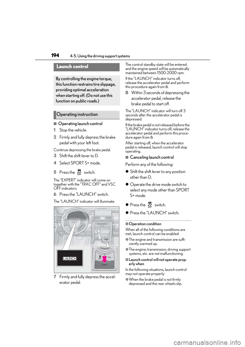
■Operating launch control
1 Stop the vehicle.
2 Firmly and fully depress the brake
pedal with your left foot.
Continue depressing the brake pedal.
3Shift the shift lever to D.
4 Select SPORT S+ mode.
5 Press the switch.
The “EXPERT” indicator will come on
together with the “TRAC OFF” and VSC
OFF indicators.
6Press the “LAUNCH” switch.
The “LAUNCH” indicator will illuminate.
7Firmly and fully depress the accel-
erator pedal.
The control standby state will be entered
and the engine speed will be automatically
maintained between 1500-2000 rpm.
If the “LAUNCH” indicator turns off,
release the accelerato r pedal and perform
this procedure again from 6.
8 Within 3 seconds of depressing the
accelerator pedal, release the
brake pedal to start off.
The “LAUNCH” indicator will turn off 3
seconds after the accelerator pedal is
depressed.
If the brake pedal is no t released before the
“LAUNCH” indicator turns off, release the
accelerator pedal and perform this proce-
dure again from 6 .
After starting off, when the accelerator
pedal is released, laun ch control will stop
operating.
■Canceling launch control
Perform any of the following:
Shift the shift lever to any position
other than D.
Operate the drive mode switch to
select any mode other than SPORT
S+ mode.
Press the switch.
Press the “LAUNCH” switch.
■Operation condition
When all of the following conditions are
met, launch control can be enabled:
●The engine and transmission are suffi-
ciently warmed up.
●The engine, transmission, driving support
systems, etc. are not malfunctioning.
■Launch control will not operate prop-
erly when
In the following situations, launch control
may not operate properly:
●When the brake pedal is not firmly
depressed and the rear wheels slip.
Launch control
By controlling the engine torque,
this function restrains tire slippage,
providing optimal acceleration
when starting off. (Do not use this
function on public roads.)
Operating instruction
Page 199 of 408
1994-5. Using the driving support systems
4
Driving
■ABS (Anti-lock Brake System)
Helps to prevent wheel lock when the
brakes are applied suddenly, or if the
brakes are applied while driving on a
slippery road surface
■Brake assist
Generates an increased level of brak-
ing force after the brake pedal is
depressed when the system detects a
panic stop situation
■VSC (Vehicle Stability Control)
Helps the driver to control skidding
when swerving sudden ly or turning on
slippery road surfaces
■Enhanced VSC (Enhanced Vehi-
cle Stability Control)
Provides cooperative control of the
ABS, TRAC, VSC and EPS.
Helps to maintain directional stability
when swerving on slippery road sur-
faces by controlling steering perfor-
mance.
■TRAC (Traction Control)
Helps to maintain drive power and pre-
vent the drive wheels from spinning
when starting the vehicle or accelerat-
ing on slippery roads
■Hill-start assist control
Helps to reduce the backward move-
ment of the vehicle when starting on an
uphill
■EPS (Electric Power Steering)
Employs an electric motor to reduce
the amount of effort needed to turn the
steering wheel
■Adaptive Variable Suspension Sys-
tem
By independently controlling the
damping force of th e shock absorbers
for each of the 4 wheels according to
the road and driving conditions, this
system combines riding comfort with
superior vehicle stability, and helps
good vehicle posture.
■VDIM (Vehicle Dynamics Inte-
grated Management)
Provides integrated control of the
ABS, brake assist, TRAC, VSC,
hill-start assist control and EPS systems
Helps to maintain vehicle stability when
swerving on slippery road surfaces by
controlling the brakes, engine output
and steering assist.
■When the TRAC/VSC systems are
operating
The slip indicator light will flash while the
TRAC/VSC systems are operating.
Driving assist systems
To keep enhance driving safety and
performance, the following systems
operate automatically in response
to various driving situations. Be
aware, however, that these systems
are supplementary and should not
be relied upon too heavily when
operating the vehicle.
Summary of the driving assist
systems
Page 201 of 408
2014-5. Using the driving support systems
4
Driving
cator light continues to remain on, contact
your Lexus dealer.
■Operating conditions of hill-start assist
control
When the following four conditions are met,
the hill-start assist control will operate:
●The shift lever is in a position other than P
or N (when starting off forward/back-
ward on an upward incline).
●The vehicle is stopped.
●The accelerator pedal is not depressed.
●The parking brake is not engaged.
■Automatic system cancelation of
hill-start assist control
The hill-start assist control will turn off in any
of the following situations:
●The shift lever is moved to P or N.
●The accelerator pedal is depressed.
●The parking brake is engaged.
●Approximately 2 seconds elapse after
the brake pedal is released.
■Sounds and vibrations caused by the
ABS, brake assist, VSC, TRAC and
hill-start assist control systems
●A sound may be heard from the engine
compartment when the brake pedal is
depressed repeatedly, when the engine is
started or just after the vehicle begins to
move. This sound does not indicate that a
malfunction has occurred in any of these
systems.
●Any of the following conditions may
occur when the above systems are oper-
ating. None of these indicates that a mal-
function has occurred.
• Vibrations may be felt through the vehicle
body and steering.
• A motor sound may be heard after the vehicle comes to a stop.
• The brake pedal may pulsate slightly after the ABS is activated.
• The brake pedal may move down slightly after the ABS is activated.
■EPS operation sound
When the steering wheel is operated, a
motor sound (whirring sound) may be
heard. This does not indicate a malfunction.
■Reactivation of the TRAC/VSC systems
Even after the TRAC /VSC systems have
been turned off, turning the engine off and
then on again will automatically reactivate
the TRAC/VSC systems.
■Reactivation of the TRAC system linked
to vehicle speed
When only the TRAC system is turned off,
the TRAC system will turn on when vehicle
speed increases. Ho wever, when both
TRAC/VSC systems are turned off, the sys-
tems will not turn on even when vehicle
speed increases.
■Reduced effectiveness of the EPS sys-
tem
The effectiveness of the EPS system is
reduced to prevent the system from over-
heating when there is frequent steering
input over an extended period of time. The
steering wheel may feel heavy as a result.
Should this occur, re frain from excessive
steering input or stop the vehicle and turn
the engine off. The EPS system should
return to normal within 10 minutes.
WARNING
■The ABS does not operate effectively
when
●The limits of tire gripping performance
have been exceeded (such as exces-
sively worn tires on a snow covered
road).
●The vehicle hydroplanes while driving
at high speed on wet or slick roads.
■Stopping distance when the ABS is
operating may exceed that of normal
conditions
The ABS is not designed to shorten the
vehicle’s stopping di stance. Always main-
tain a safe distance from the vehicle in
front of you, especially in the following
situations:
●When driving on dirt, gravel or
snow-covered roads
●When driving over bumps in the road
Page 234 of 408
2345-5. Using the other interior features
if the garage door opener motor used
is a compatible device. (To check
device compatibility, refer to
www.homelink.com.)
1Within 5 seconds after program-
ming the garage door opener has
been completed, if the garage door
opener motor is trained to Home-
Link
®, both garage door operation
indicators will flash rapidly (green)
and the light on the garage door
opener motor will b link twice, indi-
cating that 2-way communication is
enabled.
If the indicators do not flash, perform 2 and
3 within the first 10 presses of the Home-
Link
® button after programming has been
completed.
2 Press a programmed HomeLink®
button to operate a garage door.
3 Within 1 minute of pressing the
HomeLink
® button, after the
garage door operation has
stopped, press the “Learn” or
“Smart” button on the garage door
opener motor. Within 5 seconds of
the establishment of 2-way com-
munication with the garage door
opener, both garage door opera-
tion indicators in the vehicle will
flash rapidly (green) and the light
on the garage door opener motor
will blink twice, indicating that
2-way communication is enabled.
■Reprogramming a single Home-
Link
® button
When the following procedure is per-
formed, buttons which already have devices registered to them can be
overwritten:
1
With one hand, press and hold the
desired HomeLink
® button.
2 When the HomeLink
® indicator
starts flashing (orange), continue to
hold the HomeLink
® button and
perform “Programming Home-
Link
®” 1(it takes 20 seconds for
the HomeLink
® indicator to start
flashing).
■Before programming
●Install a new battery in the transmitter.
●The battery side of the transmitter must
be pointed away from the HomeLink®.
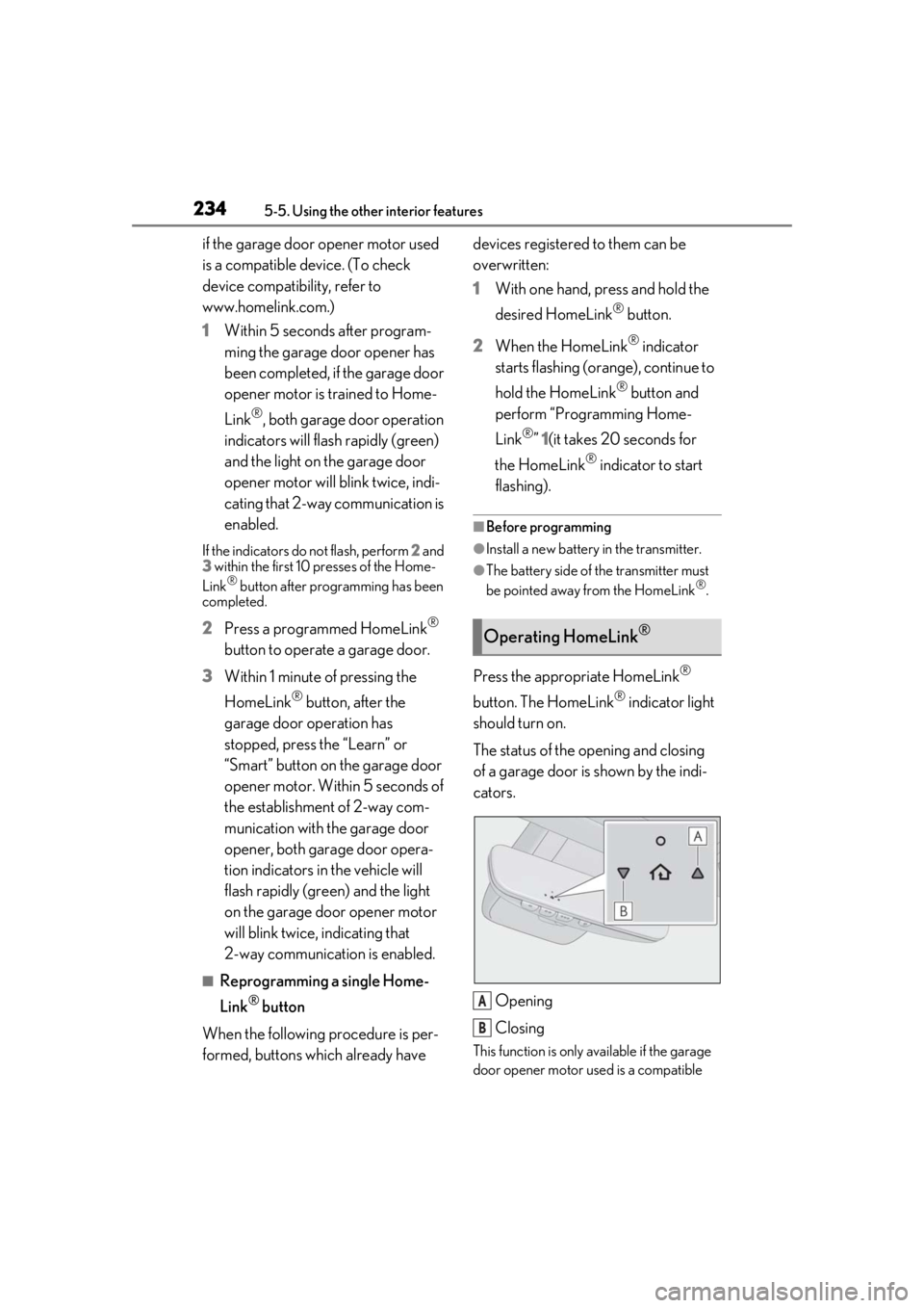
Press the appropriate HomeLink®
button. The HomeLink
® indicator light
should turn on.
The status of the opening and closing
of a garage door is shown by the indi-
cators.
Opening
Closing
This function is only available if the garage
door opener motor used is a compatible
Operating HomeLink®
A
B
Page 293 of 408

293
7
7
When trouble arises
When trouble arises
.7-1. Essential informationEmergency flashers.................. 294
If your vehicle has to be stopped in an emergency .......................... 294
If the vehicle is trapped in rising water............................................ 295
7-2. Steps to take in an emergency If your vehicle needs to be towed........................................................ 297
If you think something is wrong ........................................................ 300
Fuel pump shut off system ...... 301
If a warning light turns on or a warning buzzer sounds ....... 302
If a warning message is displayed ......................................................... 310
If you have a flat tire (vehicles with a spare tire) ................................ 313
If you have a flat tire (vehicles with an emergency tire puncture
repair kit) .................................... 319
If the engine wi ll not start .......329
If you lose your keys .................. 331
If the fuel filler door cannot be opened......................................... 331
If the electronic key does not operate properly .................... 332
If the vehicle battery is discharged ........................................................ 334
If your vehicle overheats ........ 337
If the vehicle becomes stuck ........................................................ 339
Page 301 of 408
3017-2. Steps to take in an emergency
7
When trouble arises
Follow the procedure below to restart
the engine after the system is activated.
1Turn the engine switch to ACCES-
SORY mode or turn it off.
2 Restart the engine.
Fuel pump shut off system
To minimize the risk of fuel leakage
when the engine stalls or when an
airbag inflates upon collision, the
fuel pump shut off system stops the
supply of fuel to the engine.
Restarting the engine
NOTICE
■Before starting the engine
Inspect the ground under the vehicle.
If you find that fuel has leaked onto the
ground, the fuel system has been dam-
aged and is in need of repair. Do not
restart the engine.
Page 309 of 408

3097-2. Steps to take in an emergency
7
When trouble arises
WARNING
●If the tire pressure warning light comes
on even after tire inflation pressure
adjustment, it is probable that you have
a flat tire. Check the tires. If a tire is flat,
change it with the spare tire and have
the flat tire repaired by the nearest
Lexus dealer.
●Avoid abrupt maneuvering and brak-
ing. If the vehicle tires deteriorate, you
could lose control of the steering
wheel or the brakes.
Vehicles with an emergency tire punc-
ture repair kit
●Stop your vehicle in a safe place as
soon as possible. Adjust the tire infla-
tion pressure immediately.
●If the tire pressure warning light comes
on even after tire inflation pressure
adjustment, it is probable that you have
a flat tire. Check the tires. If a tire is flat,
repair the flat tire by using emergency
tire puncture repair kit.
●Avoid abrupt maneuvering and brak-
ing. If the vehicle tires deteriorate, you
could lose control of the steering
wheel or the brakes.
■If a blowout or sudden air leakage
should occur
The tire pressure warning system may
not activate immediately.
■Maintenance of the tires
Each tire, including the spare (if pro-
vided), should be checked monthly when
cold and inflated to the inflation pressure
recommended by the vehicle manufac-
turer on the vehicle placard or tire infla-
tion pressure label (tire and load
information label). (I f your vehicle has
tires of a different size than the size indi-
cated on the vehicle placard or tire infla-
tion pressure label [tire and load
information label], yo u should determine
the proper tire infl ation pressure for
those tires.)
As an added safety fe ature, your vehicle
has been equipped with a tire pressure
monitoring system (TPMS-tire pressure
warning system) that illuminates a low
tire pressure telltale (tire pressure warn-
ing light) when one or more of your tires
is significantly under-inflated. Accord-
ingly, when the low ti re pressure telltale
(tire pressure warning light) illuminates,
you should stop and check your tires as
soon as possible, and inflate them to the
proper pressure. Driving on a signifi-
cantly under-inflated tire causes the tire
to overheat and can lead to tire failure.
Under-inflation also reduces fuel effi-
ciency and tire tread life, and may affect
the vehicle’s handling and stopping abil-
ity.
Please note that the TPMS (tire pressure
warning system) is not a substitute for
proper tire maintenance, and it is the
driver’s responsibility to maintain correct
tire pressure, even if under-inflation has
not reached the level to trigger illumina-
tion of the TPMS low tire pressure telltale
(tire pressure warning light).
Your vehicle has also been equipped with
a TPMS (tire pressure warning system)
malfunction indicator to indicate when
the system is not operating properly. The
TPMS (tire pressure warning system)
malfunction indicator is combined with
the low tire pressure telltale (tire pres-
sure warning light) . When the system
detects a malfunction, the telltale will
flash for approximately one minute and
then remain continuously illuminated.
This sequence will continue upon subse-
quent vehicle start-ups as long as the
malfunction exists. When the malfunction
indicator is illuminated, the system may
not be able to detect or signal low tire
pressure as intended.
Page 333 of 408
3337-2. Steps to take in an emergency
7
When trouble arises
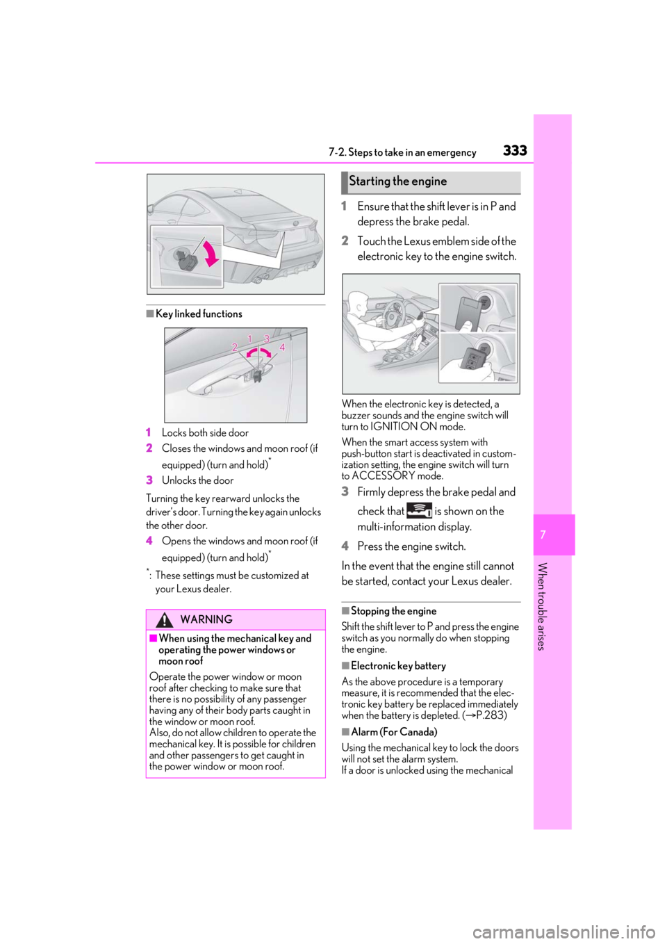
■Key linked functions
1 Locks both side door
2 Closes the windows and moon roof (if
equipped) (turn and hold)
*
3Unlocks the door
Turning the key rearward unlocks the
driver’s door. Turning the key again unlocks
the other door.
4 Opens the windows and moon roof (if
equipped) (turn and hold)
*
*
: These settings must be customized at
your Lexus dealer.
1 Ensure that the shift lever is in P and
depress the brake pedal.
2 Touch the Lexus emblem side of the
electronic key to the engine switch.
When the electronic key is detected, a
buzzer sounds and the engine switch will
turn to IGNITION ON mode.
When the smart access system with
push-button start is deactivated in custom-
ization setting, the engine switch will turn
to ACCESSORY mode.
3 Firmly depress the brake pedal and
check that is shown on the
multi-information display.
4 Press the engine switch.
In the event that the engine still cannot
be started, contact your Lexus dealer.
■Stopping the engine
Shift the shift lever to P and press the engine
switch as you normally do when stopping
the engine.
■Electronic key battery
As the above procedure is a temporary
measure, it is recommended that the elec-
tronic key battery be replaced immediately
when the battery is depleted. ( P.283)
■Alarm (For Canada)
Using the mechanical ke y to lock the doors
will not set the alarm system.
If a door is unlocked using the mechanical
WARNING
■When using the mechanical key and
operating the power windows or
moon roof
Operate the power window or moon
roof after checking to make sure that
there is no possibilit y of any passenger
having any of their body parts caught in
the window or moon roof.
Also, do not allow ch ildren to operate the
mechanical key. It is possible for children
and other passengers to get caught in
the power window or moon roof.
Starting the engine