Temperature control MAZDA 6 2002 Suplement Owner's Manual
[x] Cancel search | Manufacturer: MAZDA, Model Year: 2002, Model line: 6, Model: MAZDA 6 2002Pages: 909, PDF Size: 17.16 MB
Page 177 of 909

ON-BOARD DIAGNOSTIC
F2–25
F2
P0112 IAT sensor No.2 circuit low input Input voltage from IAT sensor No.2 is below 0.1 V.××
P0113 IAT sensor No.2 circuit high input Input voltage from IAT sensor No.2 is above 5.0 V.××
P0117 ECT sensor circuit low input Input voltage from ECT sensor is below 0.1 V.××
P0118 ECT sensor circuit high input Input voltage from ECT sensor is above 5.0V.××
P0121Accelerator position sensor No.1 circuit
performance problemInput voltage from accelerator position sensor No.1
is above 1.3 V when accelerator pedal is
depressed.××
P0122Accelerator position sensor No.1 circuit
low inputInput voltage from accelerator position sensor No.1
is below 0.3 V.××
P0123Accelerator position sensor No.1 circuit
high inputInput voltage from accelerator position sensor No.1
is above 4.7 V.××
P0182 Fuel temperature sensor circuit low inputInput voltage from fuel temperature sensor is below
0.1 V.××
P0183 Fuel temperature sensor circuit high inputInput voltage from fuel temperature sensor is above
5.0 V.××
P0191Fuel pressure sensor circuit performance
problemPressure difference between actual fuel pressure
and target fuel pressure exceeds preprogrammed
criteria.××
P0192 Fuel pressure sensor circuit low inputInput voltage from fuel pressure sensor is below 0.4
V.××
P0193 Fuel pressure sensor circuit high inputInput voltage from fuel pressure sensor is above
4.8 V.××
P0200 Fuel injector circuit malfunction Injection confirmation signal is not input normally.××
P0221Accelerator position sensor No.2 circuit
performance problemVoltage difference between accelerator position
sensor No.1 and accelerator position sensor No.2
exceeds 0.9 V.××
P0222Accelerator position sensor No.2 circuit
low inputInput voltage from accelerator position sensor No.2
is below 0.3 V.××
P0223Accelerator position sensor No.2 circuit
high inputInput voltage from accelerator position sensor No.2
is above 4.7 V.××
P0300 Random misfire detectionInterval time of CKP sensor input signal exceeds
preprogrammed criteria.××
P0336 CKP sensor circuit performance problemInput signal from CKP sensor is not proper pulse
number.××
P0337 CKP sensor circuit low inputInput signal from CKP sensor is not input at 12
crankshaft revolutions.××
P0341 CMP sensor circuit performance problemInput signal from CMP sensor is not proper pulse
number.××
P0342 CMP sensor circuit low inputInput signal from CMP sensor is not input at 12
crankshaft revolutions.××
P0380 Glow plug relay circuit malfunctionInput voltage from glow plug relay is as following:
—1.0 V or below when glow plug relay is on.
—4.0 V or above when glow plug relay is off.××
P0504Brake switch signal correlation
malfunctionInput signal from brake switch 1 brake switch 2 is as
following:.
—Brake switch 1 is ON and brake switch 2 is ON.
—Brake switch 1 is OFF and brake switch 2 is
OFF.××
P0510 Idle switch circuit malfunctionInput voltage from idle switch is B+ when
accelerator position sensor No.1 voltage is below
0.7 V.××
P0512 Engine switch circuit malfunctionInput voltage from engine switch is B+ when engine
speed is 1,200 rpm or above.××
P0564 Cruise control signal malfunctionInput voltage from cruise control switch is as
following for 120 s:
—Below 0.1 V.
—1.4—1.9 V.
—3.7—3.9 V.
—4.5—4.6 V.××
P0602 PCM programming error No configuration data in PCM.××
P0606 PCM malfunction PCM does not read DTC from output devices.×× DTC Condition Detection condition MILMemory
function
Page 179 of 909

ON-BOARD DIAGNOSTIC
F2–27
F2
PID/DATA MONITOR AND RECORDA6E407018881204PID monitoring item table
End Of Sie
SIMULATION TESTA6E407018881205Simulation test item table
×: Applicable
Item Definition Condition/unit PCM terminal
ACCS A/C relay ON/OFF 73
ACSW A/C switch ON/OFF 84
APS1 Accelerator position sensor No.1 signal voltage V 10
APS2 Accelerator position sensor No.2 signal voltage V 88
BAROBarometric pressure kPa, inHg
-
Barometric pressure signal voltage V
BOO Brake switch ON/OFF 7
CPP Clutch switch ON/OFF 33
CPP/PNP Neutral switch Neutral/Drive 56
CRUISESW Cruise control switch ON/OFF 64
DTCCNT DTC count - -
ECTEngine coolant temperature°C, °F
87
Engine coolant temperature signal voltage V
FAN2 Cooling fan relay No.2 ON/OFF 76
FAN3 Cooling fan relay No.1 ON/OFF 102
IATIntake air temperature°C, °F
60
Intake air temperature signal voltage V
IMRC VSC solenoid valve ON/OFF 101
INGEAR In gear ON/OFF 33, 56
INJ_LRN_DIS Distance from the last injector learning Km, Mile -
MAFMass air flow amount g/s
9
Mass air flow signal voltage V
MAF_LRN_DIS Distance from the last MAF learning Km, Mile -
MAINRLY PCM control relay ON/OFF 69
MAPManifold absolute pressure kPa, inHg
36
Manifold absolute pressure signal voltage V
MIL Malfunction indicator lamp ON/OFF 71
NUMKEYS Number of keys stored in module - -
RPM Engine speed rpm 3, 29
VPWR Battery positive voltage V 27
VSS Vehicle speed km/h, mph 13, 39
Item Definition OperationTest condition
PCM
terminal
Key ON Idle
ACCS A/C relay ON or OFF××73
EGRA EGR solenoid valve (vent)Actuated by any duty value
(0—100%)××72
EGRV EGR solenoid valve (vacuum)Actuated by any duty value
(0—100%)××99
EGRV2 EGR control solenoid valve ON or OFF××77
FAN Cooling fan No.2 ON or OFF××76
FAN3 Cooling fan No.1 ON or OFF××102
GP_LMP Glow indicator light ON or OFF××97
GPC Glow plug relay ON or OFF××68
IASV Intake shutter solenoid valve (half) ON or OFF××74
IASV2 Intake shutter solenoid valve (full) ON or OFF××100
IMRC VSC solenoid valve ON or OFF××101
VBCV VBC solenoid valveActuated by any duty value
(0—100%)××67
Page 206 of 909
F2–54
FUEL SYSTEM
SUPPLY PUMP INSPECTIONA6E401213350202
Caution
•The supply pump is sealed to maintain proper function. Special tools and testers are required
when disassembling the supply pump. Disassembling the supply pump without special tools and
testers will cause a malfunction.
•Consult an authorized DENSO parts distributor for repair if any of the following supply pump parts
are possibly malfunctioning.
1. Supply pump inner parts
2. Suction control valve
3. Fuel temperature sensor
End Of Sie
SUCTION CONTROL VALVE INSPECTIONA6E401213350203
Caution
•The supply pump is sealed to maintain proper function. Special tools and testers are required
when disassembling the supply pump. Disassembling the supply pump without special tools and
testers will cause a malfunction.
•Consult an authorized DENSO parts distributor for repair if suction control valve is possibly
malfunctioning.
Resistance Inspection
1. Disconnect the negative battery cable.
2. Disconnect the suction control valve connector.
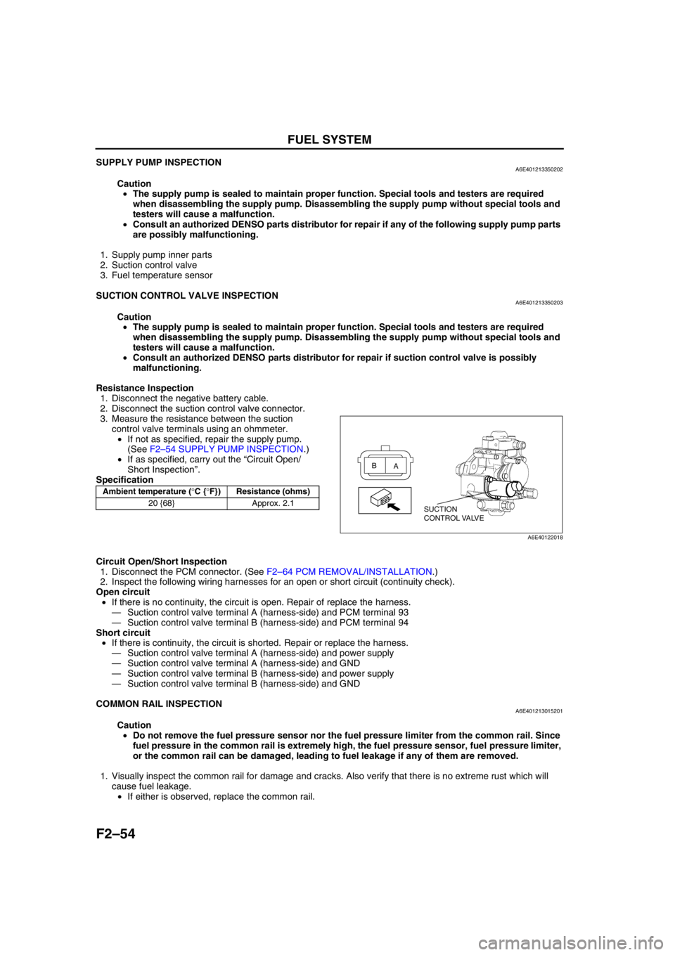
3. Measure the resistance between the suction
control valve terminals using an ohmmeter.
•If not as specified, repair the supply pump.
(See F2–54 SUPPLY PUMP INSPECTION.)
•If as specified, carry out the “Circuit Open/
Short Inspection”.
Specification
Circuit Open/Short Inspection
1. Disconnect the PCM connector. (See F2–64 PCM REMOVAL/INSTALLATION.)
2. Inspect the following wiring harnesses for an open or short circuit (continuity check).
Open circuit
•If there is no continuity, the circuit is open. Repair of replace the harness.
—Suction control valve terminal A (harness-side) and PCM terminal 93
—Suction control valve terminal B (harness-side) and PCM terminal 94
Short circuit
•If there is continuity, the circuit is shorted. Repair or replace the harness.
—Suction control valve terminal A (harness-side) and power supply
—Suction control valve terminal A (harness-side) and GND
—Suction control valve terminal B (harness-side) and power supply
—Suction control valve terminal B (harness-side) and GND
End Of Sie
COMMON RAIL INSPECTIONA6E401213015201
Caution
•Do not remove the fuel pressure sensor nor the fuel pressure limiter from the common rail. Since
fuel pressure in the common rail is extremely high, the fuel pressure sensor, fuel pressure limiter,
or the common rail can be damaged, leading to fuel leakage if any of them are removed.
1. Visually inspect the common rail for damage and cracks. Also verify that there is no extreme rust which will
cause fuel leakage.
•If either is observed, replace the common rail.
End Of Sie
Ambient temperature (°C {°F}) Resistance (ohms)
20 {68} Approx. 2.1
SUCTION
CONTROL VALVE A B
A6E40122018
Page 217 of 909
CONTROL SYSTEM
F2–65
F2
End Of SiePCM INSPECTIONA6E404018881208Using WDS or Equivalent
Caution
•The PCM terminal voltage vary with change in measuring conditions and vehicle conditions.
Always carry out a total inspection of the input systems, output systems, and PCM to determine
the cause of trouble. Otherwise, diagnosis will be incorrect.
Note
•For replace the PCM, setup the WDS and perform the following.
—“PCM configuration” (See F2–68 PCM CONFIGURATION.)
—“Correction after Parts Installation” (See F2–34 Correction after Parts Installation.)
1. Connect the WDS or equivalent to the DLC-2. (See F2–85 ON-BOARD DIAGNOSTIC TEST.)
2. Turn the engine switch to ON.
3. Measure the PID value.
•If PID value is not within the specification, follow the instructions in ACTION column.
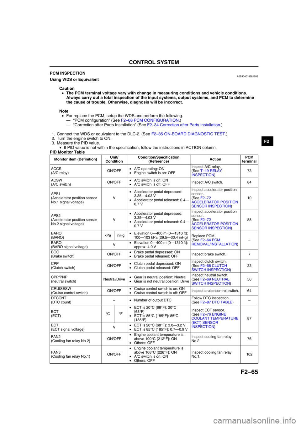
PID Monitor Table
Monitor item (Definition)Unit/
ConditionCondition/Specification
(Reference)ActionPCM
terminal
ACCS
(A/C relay)ON/OFF•A/C operating: ON
•Engine switch is on: OFFInspect A/C relay.
(See T–19 RELAY
INSPECTION)73
ACSW
(A/C switch)ON/OFF•A/C switch is on: ON
•A/C switch is off: OFFInspect A/C switch. 84
APS1
(Accelerator position sensor
No.1 signal voltage)V•Accelerator pedal depressed:
3.35—4.03 V
•Accelerator pedal released: 0.4—
0.7 VInspect accelerator position
sensor.
(See F2–72
ACCELERATOR POSITION
SENSOR INSPECTION)10
APS2
(Accelerator position sensor
No.2 signal voltage)V•Accelerator pedal depressed:
3.35—4.03 V
•Accelerator pedal released: 0.4—
0.7 VInspect accelerator position
sensor.
(See F2–72
ACCELERATOR POSITION
SENSOR INSPECTION)88
BARO
(BARO)kPa inHg•Elevation 0—400 m {0—1310 ft}:
100—103 kPa {29.5—30.4 inHg}Replace PCM.
(See F2–64 PCM
REMOVAL/INSTALLATION)–
BARO
(BARO signal voltage)V•Elevation 0—400 m {0—1310 ft}:
approx. 4.0 V
BOO
(Brake switch)ON/OFF•Brake pedal depressed: ON
•Brake pedal released: OFFInspect brake switch. 7
CPP
(Clutch switch)ON/OFF•Clutch pedal depressed: ON
•Clutch pedal released: OFFInspect clutch switch.
(See F2–68 CLUTCH
SWITCH INSPECTION)33
CPP/PNP
(neutral switch)Neutral/Drive•Gear is neutral position: Neutral
•Gear is not neutral position: DriveInspect neutral switch.
(See F2–69 NEUTRAL
SWITCH INSPECTION)56
CRUISESW
(Cruise control switch)ON/OFF•Cruise control switch is on: ON
•Cruise control switch is off: OFFInspect cruise control switch. 64
DTCCNT
(DTC count)–•Number of output DTCFollow DTC inspection.
(See F2–87 DTC TABLE)–
ECT
(ECT)°C°F•ECT is 20°C {68°F}: 20°C
{68°F}
•ECT is 85°C {185°F}: 85°C
{185°F}Inspect ECT sensor.
(See F2–76 ENGINE
COOLANT TEMPERATURE
(ECT) SENSOR
INSPECTION)87
ECT
(ECT signal voltage)V•ECT is 20°C {68°F}: 3.0—3.2 V
•ECT is 85°C {185°F}: 0.7—0.9 V
FAN2
(Cooling fan relay No.2)ON/OFF•Engine coolant temperature is
above 100°C {212°F}: ON
•Others: OFFInspect cooling fan relay
No.2.76
FAN3
(Cooling fan relay No.1)ON/OFF•Engine coolant temperature is
above 108°C {226°F}: ON
•A/C switch is on: ON
•Others: OFFInspect cooling fan relay
No.1.102
Page 218 of 909

F2–66
CONTROL SYSTEM
IAT
(IAT)°C°F•IAT is 20°C {68°F}: 20°C {68°F}
•IAT is 30°C {86°F}: 30°C {86°F}Inspect IAT sensor No.1.
(See F2–74 MASS AIR
FLOW (MAF)/INTAKE AIR
TEMPERATURE (IAT)
SENSOR INSPECTION)60
IAT
(IAT signal voltage)V•IAT is 20°C {68°F}: 2.2—2.5 V
•IAT is 30°C {86°F}: 1.7—2.0 V
IMRC
(VSC solenoid valve)ON/OFF•Idle: ON
•Engine speed is above approx.
2,500 rpm: OFFInspect following PIDs:
BARO, ECT, IAT, RPM, VSS101
INGEAR
(In gear)ON/OFF•Gear is not neutral position and
clutch pedal released: ON
•Gear is neutral position: OFF
•Clutch pedal depressed: OFFInspect following PIDs:
CPP, CPP/PNP33, 56
INJ_LRN_DIS
(Distance from the last
injector learning)Km Mile•Distance from the last injector
learning––
MAF
(Mass air flow amount)g/s•Engine switch is on: approx. 0 g/s
•Idle: 6.8—7.4 g/sInspect MAF/IAT sensor.
(See F2–74 MASS AIR
FLOW (MAF)/INTAKE AIR
TEMPERATURE (IAT)
SENSOR INSPECTION)9
MAF
(Mass air flow signal voltage)V•Engine switch is on: 0.0—1.0 V
•Idle: 1.5—2.1 V
MAF_LRN_DIS
(Distance from the last MAF
learning)Km Mile•Distance from the last MAF
learning––
MAINRLY
(PCM control relay)ON/OFF•Engine switch is on: ONInspect PCM control relay.
(See T–19 RELAY
INSPECTION)69
MAP
(MAP)kPa inHg•Engine switch is on: 100—103
kPa {29.5—30.4 inHg}
•Idle: 100—103 kPa {29.5—30.4
inHg}Inspect boost sensor.
(See F2–78 BOOST
SENSOR INSPECTION)36
MAP
(MAP signal voltage)V•Engine switch is on: 2.1—2.5 V
•Idle: 2.1—2.5 V
MIL
(MIL)ON/OFF•Engine switch is on: ON
•DTC output: ON
•Others: OFFInspect instrument cluster.
Inspect CAN system.
(See T–39 MULTIPLEX
COMMUNICATION
SYSTEM)13, 39
NUMKEYS
(Number of keys stored in
module)–•Number of keys stored in module––
RPM
(Engine speed)rpm•Idle: 725—825 rpmInspect CKP sensor.
(See F2–80 CAMSHAFT
POSITION (CMP) SENSOR
INSPECTION)3, 29
VPWR
(Battery positive voltage)V•Engine switch is ON: B+Inspect Battery.
Inspect fuse.4
VSS
(Vehicle speed)km/h mph•Vehicle speed is 20 km/h {12.5
mph}: 20 km/h {12.5 mph}
•Vehicle speed is 40 km/h {25
mph}: 40 km/h {25 mph}Inspect CAN system.
(See T–39 MULTIPLEX
COMMUNICATION
SYSTEM)13, 39 Monitor item (Definition)Unit/
ConditionCondition/Specification
(Reference)ActionPCM
terminal
Page 226 of 909
F2–74
CONTROL SYSTEM
MASS AIR FLOW (MAF)/INTAKE AIR TEMPERATURE (IAT) SENSOR INSPECTIONA6E404013210201
Note
•Perform the following test only when directed.
•Perform “MAF Correction” after replacing the MAF/IAT sensor. (See F2–35 MAF Correction.)
MAF Sensor Voltage Inspection
1. Turn the engine switch to ON.
2. Monitor the MAF PID using the WDS or equivalent.
•If not as specified, perform the “Circuit Open/Short Inspection”.
MAF PID
0.0—1.0 V
3. Start the engine and warm up the engine completely.
4. Monitor the MAF PID using the WDS or equivalent at idle.
•If not as specified, perform the “Circuit Open/Short Inspection”.
MAF PID
1.5—2.1 V
MAF Sensor CIrcuit Open/Short Inspection
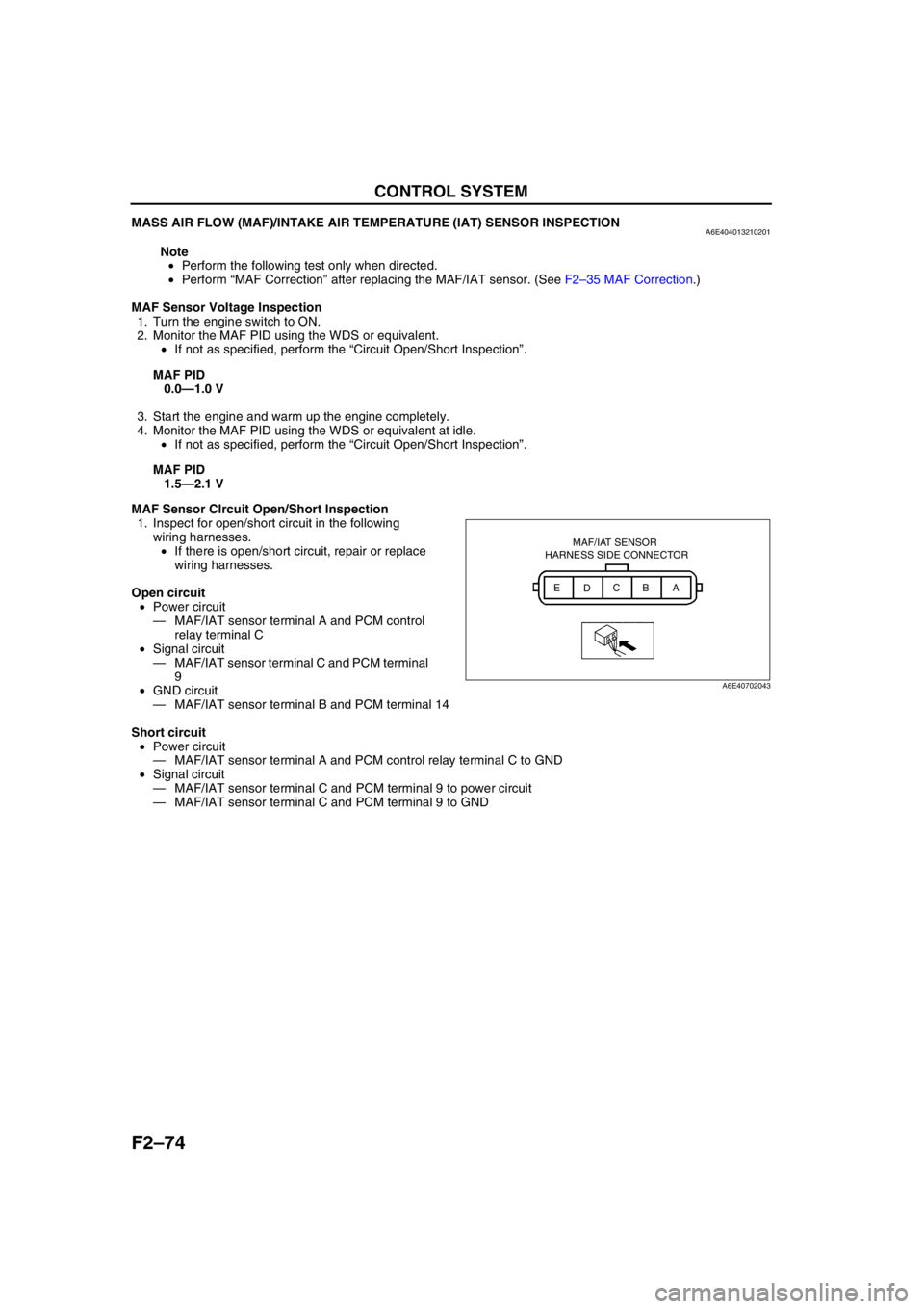
1. Inspect for open/short circuit in the following
wiring harnesses.
•If there is open/short circuit, repair or replace
wiring harnesses.
Open circuit
•Power circuit
—MAF/IAT sensor terminal A and PCM control
relay terminal C
•Signal circuit
—MAF/IAT sensor terminal C and PCM terminal
9
•GND circuit
—MAF/IAT sensor terminal B and PCM terminal 14
Short circuit
•Power circuit
—MAF/IAT sensor terminal A and PCM control relay terminal C to GND
•Signal circuit
—MAF/IAT sensor terminal C and PCM terminal 9 to power circuit
—MAF/IAT sensor terminal C and PCM terminal 9 to GND
MAF/IAT SENSOR
HARNESS SIDE CONNECTOR
A
B
C
D E
A6E40702043
Page 227 of 909

CONTROL SYSTEM
F2–75
F2
IAT Sensor No.1 Resistance Inspection
1. Disconnect the MAF/IAT sensor connector.
2. Measure the resistance between MAF/IAT sensor terminals D and E using an ohmmeter.
•If not as specified, replace the MAF/IAT sensor.
Specification
IAT Sensor No.1 CIrcuit Open/Short Inspection
1. Inspect for open/short circuit in the following wiring harnesses.
•If there is open/short circuit, repair or replace wiring harnesses.
Open circuit
•Signal circuit
—MAF/IAT sensor terminal D and PCM terminal 60
•GND circuit
—MAF/IAT sensor terminal E and PCM terminal 91
Short circuit
•Signal circuit
—MAF/IAT sensor terminal D and PCM terminal 60 to power circuit
—MAF/IAT sensor terminal D and PCM terminal 60 to GND
End Of Sie
INTAKE AIR TEMPERATURE (IAT) SENSOR NO.2 INSPECTIONA6E404018845201
Note
•Perform the following test only when directed.
Resistance Inspection
1. Place the IAT sensor No.2 in water with a thermometer, and heat the water gradually.
2. Measure the resistance between the IAT sensor
No.2 terminals using an ohmmeter.
•If not as specified, replace the IAT sensor
No.2.
Specification
Circuit Open/Short Inspection
1. Inspect for open/short circuit in the following wiring harnesses.
•If there is open/short circuit, repair or replace wiring harnesses.
Open circuit
•Signal circuit
—IAT sensor No.2 terminal A and PCM terminal 8
•GND circuit
—IAT sensor No.2 terminal B and PCM terminal 91
Short circuit
•Signal circuit
—IAT sensor No.2 terminal A and PCM terminal 8 to power circuit
—IAT sensor No.2 terminal A and PCM terminal 8 to GND
End Of Sie
Ambient temperature (°C
{°F})Resistance (kilohm)
20 {68} 2.21—2.69
Water temperature (°C {°F}) Resistance (kilohm)
20 {68} 2.21—2.69
80 {176} 0.29—0.35
A B
A6E40702044
Page 228 of 909
F2–76
CONTROL SYSTEM
ENGINE COOLANT TEMPERATURE (ECT) SENSOR REMOVAL/INSTALLATIONA6E404018840201
Warning•When the engine is hot, it can badly burn. Turn off the engine and wait until it is cool before
removing the ECT sensor.
1. Disconnect the negative battery cable.
2. Drain the engine coolant. (See Section E ENGINE COOLANT REPLACEMENT.)
3. Remove the common rail. (See F2–53 SUPPLY PUMP REMOVAL/INSTALLATION .)
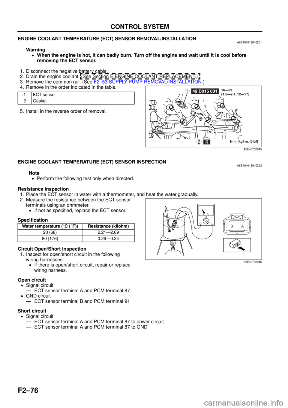
4. Remove in the order indicated in the table.
5. Install in the reverse order of removal.
End Of Sie
ENGINE COOLANT TEMPERATURE (ECT) SENSOR INSPECTIONA6E404018840202
Note
• Perform the following test only when directed.
Resistance Inspection 1. Place the ECT sensor in water with a thermometer, and heat the water gradually.
2. Measure the resistance between the ECT sensor terminals using an ohmmeter.
• If not as specified, replace the ECT sensor.
Specification
Circuit Open/Short Inspection 1. Inspect for open/short circuit in the following
wiring harnesses.• If there is open/short circuit, repair or replace
wiring harness.
Open circuit • Signal circuit
— ECT sensor terminal A and PCM terminal 87
• GND circuit
— ECT sensor terminal B and PCM terminal 91
Short circuit • Signal circuit
— ECT sensor terminal A and PCM terminal 87 to power circuit
— ECT sensor terminal A and PCM terminal 87 to GND
End Of Sie
1ECT sensor
2Gasket149 D015 001
N·m {kgf·m, ft·lbf}
16—23
{1.6—2.4, 12—17}2R
A6E40702045
Water temperature (
°C { °F}) Resistance (kilohm)
20 {68} 2.21—2.69
80 {176} 0.29—0.34A
B
A6E40702046
Page 229 of 909

CONTROL SYSTEM
F2–77
F2
FUEL TEMPERATURE SENSOR INSPECTIONA6E404013350201
Note
•Perform the following test only when directed.
Resistance Inspection
1. Disconnect the negative battery cable.
2. Remove the supply pump. (See F2–53 SUPPLY PUMP REMOVAL/INSTALLATION.)
3. Measure the resistance between the fuel
temperature sensor terminals using an
ohmmeter.
•If not as specified, repair the supply pump.
(See F2–54 SUPPLY PUMP INSPECTION.)
Specification
Circuit Open/Short Inspection
1. Inspect for open/short circuit in the following
wiring harnesses.
•If there is open/short circuit, repair or replace wiring harness.
Open circuit
•Signal circuit
—Fuel temperature sensor terminal A and PCM terminal 35
•GND circuit
—Fuel temperature sensor terminal B and PCM terminal 91
Short circuit
•Signal circuit
—Fuel temperature sensor terminal A and PCM terminal 35 to power circuit
—Fuel temperature sensor terminal A and PCM terminal 35 to GND
End Of Sie
Ambient temperature (°C
{°F})Resistance (kilohm)
20 {68} 2.0—3.0
A
B
A6E40702047
Page 233 of 909
CONTROL SYSTEM
F2–81
F2
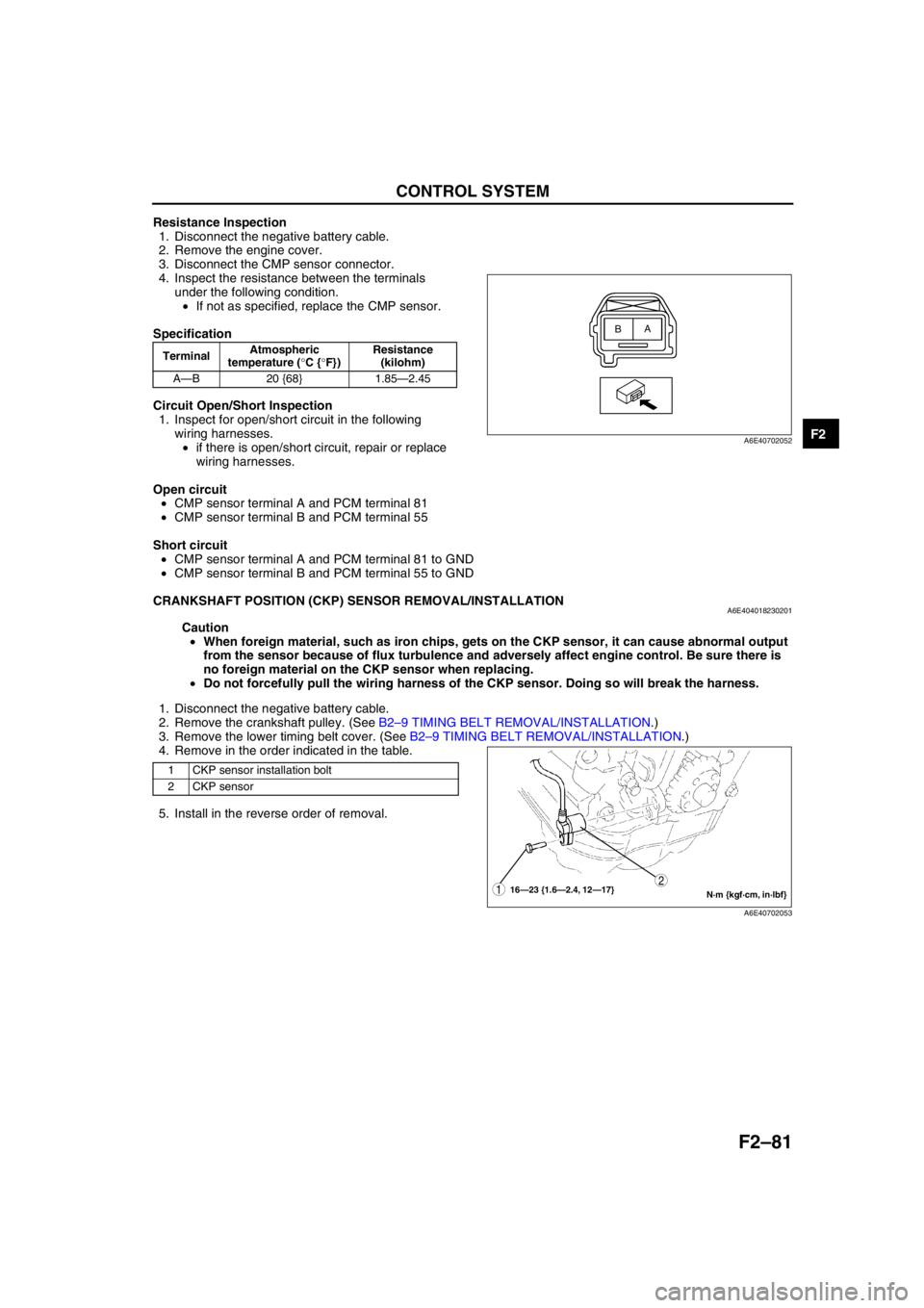
Resistance Inspection
1. Disconnect the negative battery cable.
2. Remove the engine cover.
3. Disconnect the CMP sensor connector.
4. Inspect the resistance between the terminals
under the following condition.
•If not as specified, replace the CMP sensor.
Specification
Circuit Open/Short Inspection
1. Inspect for open/short circuit in the following
wiring harnesses.
•if there is open/short circuit, repair or replace
wiring harnesses.
Open circuit
•CMP sensor terminal A and PCM terminal 81
•CMP sensor terminal B and PCM terminal 55
Short circuit
•CMP sensor terminal A and PCM terminal 81 to GND
•CMP sensor terminal B and PCM terminal 55 to GND
End Of Sie
CRANKSHAFT POSITION (CKP) SENSOR REMOVAL/INSTALLATIONA6E404018230201
Caution
•When foreign material, such as iron chips, gets on the CKP sensor, it can cause abnormal output
from the sensor because of flux turbulence and adversely affect engine control. Be sure there is
no foreign material on the CKP sensor when replacing.
•Do not forcefully pull the wiring harness of the CKP sensor. Doing so will break the harness.
1. Disconnect the negative battery cable.
2. Remove the crankshaft pulley. (See B2–9 TIMING BELT REMOVAL/INSTALLATION.)
3. Remove the lower timing belt cover. (See B2–9 TIMING BELT REMOVAL/INSTALLATION.)
4. Remove in the order indicated in the table.
5. Install in the reverse order of removal.
End Of Sie
TerminalAtmospheric
temperature (°C {°F})Resistance
(kilohm)
A—B 20 {68} 1.85—2.45
A
B
A6E40702052
1 CKP sensor installation bolt
2 CKP sensor
N·m {kgf·cm, in·lbf} 16—23 {1.6—2.4, 12—17}12
A6E40702053