light MAZDA MX-5 1994 Owner's Manual
[x] Cancel search | Manufacturer: MAZDA, Model Year: 1994, Model line: MX-5, Model: MAZDA MX-5 1994Pages: 1708, PDF Size: 82.34 MB
Page 161 of 1708

TROUBLESHOOTING GUIDE RELATIONSHIP CHART Fuel injector TEN Terminal (Data link connector) Ignition Switch (Start Position) Steering Pressure Sensor X X X X X X X X X X X X X X X xoo Blower Switch Headlight Switch Stoplight Switch Neutral and Clutch Switches (MT) Parklneutral switch (AT) Air Conditioning Sensor Idle Switch Throttle I BDL) Position Sensor I Sensor (NO) Barometric Absolute Pres- sure Sensor IGF Signal Heated Oxygen Sensor Engine Coolant Temperature Sensor Sensor Mass Air- flow Sensor Intake Air Temperature Sensor Crankshaft SGTSignal Position Sensor SGC-Signal Gartner Banana
Page 165 of 1708

TROUBLESHOOTING GUIDE Warning Fuel vapor is hazardous. It can very easily ignite, causing serious injury and damage. Always keep sparks and flames away from fuel. Fuel in the fuel system is under high pressure when the engine is not running. 4 Warning Fuel line spills and leaks are dangerous. Fuel can ignite and cause serious injuries or death and damage. Fuel can also irritate skin and eyes. To prevent this, always complete the following "Fuel Line Safety Procedures". 35UOFX-008 F-73 F-73 F-74 Fuel Line Safety Procedures A. Release the fuel pressure before disconnecting a fuel line. 1. Start the engine. u 2. Disconnect the fuel pump relay connector. 3. After the engine stalls, turn the ignition switch to OFF. 4. Reconnect the fuel pump relay connector. B. Avoid leakage. 1. When disconnecting a fuel line hose, wrap a rag around it to protect against fuel leakage. 2. Plug the hose after removal. C. Install hose clamps to secure the fuel pressure gauge connections. Self-Diagnosis Checker does not indicate Diagnostic Trouble Code No. but MIL comes on Self-Diagnosis Checker indicates Diagnostic Trouble Code No, of input device but MIL never comes ON Blower fan operates but no cool air is discharged 32 33 34 Pinching Hose When pinching an air hose or fuel hose with pliers, wrap the hose with a rag to prevent damage. MIL always ON MIL never ON NC does not work Checking ignition spark When checking ignition spark condition, hold the high- tension lead with insulated pliers. Note If a timing light is used to check for spark, some lights do not light at the number 2 and 4 cylinders even if the ignition system is normal. J Gartner Banana
Page 185 of 1708

TROUBLESHOOTING GUIDE ldle speed control malfunction Engine speed feedback control malfunction ldle air control valve stuck 12 INSPECTION LOW IDLE SPEED - WHEN AIC, PIS, OR EIL ON Check if "00" is displayed on Self-Diagnosis Check- er with ignition switch ON @? page F-79 SELECT SWA SYSTEM SELECT 1 I Check switches for correct operation with Self- Diagnosis Checker Monitor Lamp and ignition switch ON page F-95 SELECT SW A DESCRIPTIOH MONITOR [LAMP &\L SYSTEM SELECT 1 : Engine speed decreases at idle when NC, PIS, or EIL ON NC, PIS, headlights, blower fan and electric coolant fan operate normally Check if continuity exists between data link con- nector terminal TEN and ground --., rrROUBLESHOOTlNG HINTS] Disconnect idle air control valve connector at idle and check if engine condition is changed IAC VALYE CONNECTOR /' Yes - No Yes Yes No - Yes - No - ACTION Go to next step Diagnostic Trouble Code No. displayed Check for cause (Refer to specified check sequence) US= page F-81 "88" flashes Check PCME terminal 1 E voltage * page F-145 Specification: Battery positive voltage (Ignition switch ON) 6 If OK, replace PCME page F-143 G If not OK, check wiring between PCME and Self-Diagno- sis Checker page F-7 Go to next step Lamp not ONIOFF with specified switch Check for cause (Refer to specified check sequence) as page F-96 Lamp always ON Check wiring between PCME terminal I D and Self-Diag- nosis Checker @T page F-7 Check for short circuit in wiring between data link connec- tor terminal TEN and ground as page F-7 Go to next step Try known good PCME page F-144 Check idle air control valve @? page F-106 Gartner Banana
Page 199 of 1708
![MAZDA MX-5 1994 Owners Manual TROUBLESHOOTING GUIDE DESCRIPTION I : Engine unexpectedly stops running at idle when AIC, PIS, or EIL ON AX, PIS, headlight, blower fan and electric coolant fan OK 20 [TROUBLESHOOTING HINTS] O ldle sp MAZDA MX-5 1994 Owners Manual TROUBLESHOOTING GUIDE DESCRIPTION I : Engine unexpectedly stops running at idle when AIC, PIS, or EIL ON AX, PIS, headlight, blower fan and electric coolant fan OK 20 [TROUBLESHOOTING HINTS] O ldle sp](/img/28/57072/w960_57072-198.png)
TROUBLESHOOTING GUIDE DESCRIPTION I : Engine unexpectedly stops running at idle when AIC, PIS, or EIL ON AX, PIS, headlight, blower fan and electric coolant fan OK 20 [TROUBLESHOOTING HINTS] O ldle speed control malfunction No input signal from switch ldle speed misadjustment ldle air control valve stuck ENGINE STALLS AT IDLE - WHEN AIC, PIS, OR EIL ON INSPECTION Check if "00" is displayed on Self-Diagnosis Check- er with ignition switch ON * page F-79 SELECT SW A SYSTEM SELECT 1 Check switches for correct operation with Self- Diagnosis Checker Monitor Lamp and ignition switch ON tw page F-95 SELECT SW A Check if PCME terminal voltages are OK (IG, 1 P, 1 U, 2D,2Q and 2W) page F-146 Check for correct idle speed page F-77 ldle speed: 850 2 50 rpm (MT) 800 2 50 rpm (AT) GND TEN 1 AIR ADJUSTING SCREW CONNECT TERMINAL - Yes - No Yes - No Yes - No Yes - No Go to next step ACTION Diagnostic Trouble Code No. displayed Check for cause (Refer to specified check sequence) page F-81 "88" flashes Check PCME terminal 1 E voltage page F-145 Specification: Battery positive voltage (Ignition switch ON) 0 If OK, replace PCME page F-143 s If not OK, check wiring between PCME and Self-Diagno- sis Checker page F-7 Go to next step Lamp not ONlOFF with specified switch Check for cause (Refer to specified check sequence) page F-96 Lamp always ON Check wiring between PCME terminal 1 D and Self-Diag- nosis Checker IS page F-7 Go to next step Check for cause (Refer to "Check Point for Each Termi- nal") page F-148 Go to next step Adjust page F-77 Gartner Banana
Page 225 of 1708

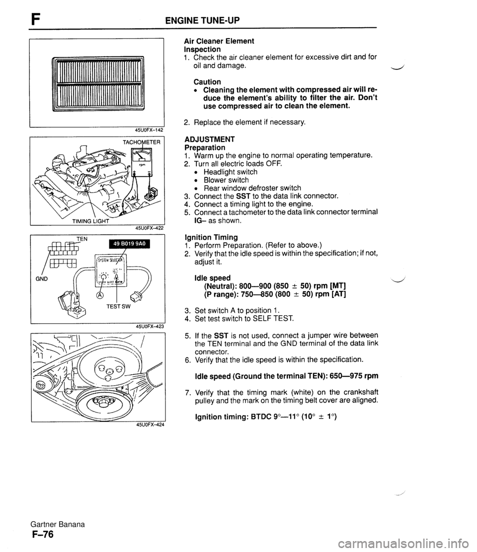
ENGINE TUNE-UP - TIMING LIGHT - 45UOFX422 GND Irnr Air Cleaner Element Inspection 1. Check the air cleaner element for excessive dirt and for oil and damage. Caution Cleaning the element with compressed air will re- duce the element's ability to filter the air. Don't use compressed air to clean the element. 2. Replace the element if necessary. ADJUSTMENT Preparation 1. Warm up the engine to normal operating temperature. 2. Turn all electric loads OFF. Headlight switch Blower switch Rear window defroster switch 3. Connect the SST to the data link connector. 4. Connect a timing light to the engine. 5. Connect a tachometer to the data link connector terminal IG- as shown. Ignition Timing 1. Perform Preparation. (Refer to above.) 2. Verify that the idle speed is within the specification; if not, adjust it. Idle speed 4 (Neutral): 800-900 (850 + 50) rpm [MT] (P range): 750-850 (800 & 50) rpm [AT] 3. Set switch A to position 1. 4. Set test switch to SELF TEST. 5. If the SST is not used, connect a jumper wire between the TEN terminal and the GND terminal of the data link connector. 6. Verify that the idle speed is within the specification. ldle speed (Ground the terminal TEN): 650-975 rpm 7. Verify that the timing mark (white) on the crankshaft pulley and the mark on the timing belt cover are aligned. lgnition timing: BTDC 9"-11" (10" & lo) Gartner Banana
Page 229 of 1708

ON-BOARD DIAGNOSIS SYSTEM Principle of Code Cycle Diagnostic trouble codes are determined as shown below. 1. Code cycle break The time between diagnostic trouble code cycles is 4.0 seconds (the time the lamp is off). 1 CYCLE DIAGNOSTIC I I TROUBLE CODE, CYCLE BREAK I JUU I I C-----------l 4.0 SEC. 2. Second digit of diagnostic trouble code (ones position) The digit in the ones position of the diagnostic trouble code represents the number of times the buzzer sounds 0.4 second during one cycle. I 1 1 CYCLE DIAGNOSTIC DIAGNOSTIC ON TROUBLE CODE I TROUBLE 1 2 3 CYCLE BREAK CODE: 03 UICCl4 4.0 4.0 4.0 SEC. SEC. SEC. 3. First digit of diagnostic trouble code (tens position) The digit in the tens position of the diagnostic trouble code represents the number of times the buzzer is on 1.2 seconds during one cycle. It should also be noted that the light goes off for 1.6 seconds between the long and short pulses of the buzzer. r 1 CYCLE DIAGNOSTIC DIAGNOSTIC . TROUBLE CODE TROUBLE L 12 CODE: 22 - FIRST DIGIT SECOND DIGIT Gartner Banana
Page 244 of 1708

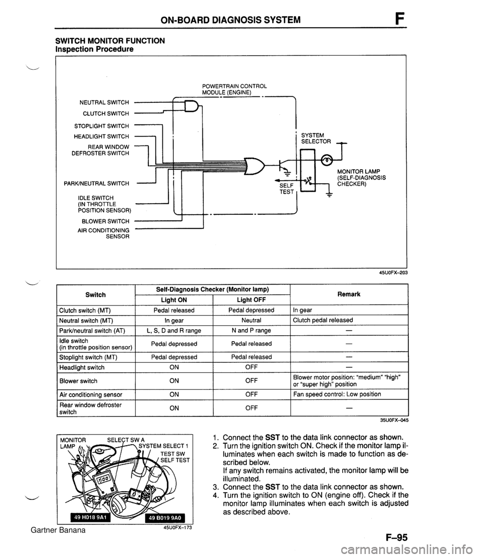
ON-BOARD DIAGNOSIS SYSTEM SWITCH MONITOR FUNCTION Inspection Procedure POWERTRAIN CONTROL MODULE (ENGINE) NEUTRAL SWITCH CLUTCH SWITCH 1 STOPLIGHT SWITCH HEADLIGHT SWITCH REAR WINDOW DEFROSTER SWITCH PARKINEUTRAL SWITCH IDLE SWITCH (IN THROTTLE POSITION SENSOR) BLOWER SWITCH AIR CONDITIONING SENSOR I ' SYSTEM MONITOR LAMP (SELF-DIAGNOSIS 1 Clutch switch (MT) 1 Pedal released I Pedal depressed I In gear I Switch Self-Diagnosis Checker (Monitor lamp) I Liaht ON Liaht OFF . . I I I - I Idle switch (in throttle position sensor) I Pedal depressed I Pedal released 1 Remark ParWneutral switch (AT) I L, S, D and R range I N and P range I I I Stoplight switch (MT) Pedal depressed I Pedal released - I Neutral I Clutch pedal released Neutral switch (MT) - In gear I I Blower switch Headlight switch OFF Blower motor position: "medium" "high" or "super hiah" position I I ON 1. Connect the SST to the data link connector as shown. 2. Turn the ignition switch ON. Check if the monitor lamp il- luminates when each switch is made to function as de- scribed below. If any switch remains activated, the monitor lamp will be illuminated. 3. Connect the SST to the data link connector as shown. 4. Turn the ignition switch to ON (engine off). Check if the monitor lamp illuminates when each switch is adjusted as described above. 45UOFX-173 OFF 1 Air conditioning sensor Rear window defroster switch - ON ON OFF OFF Fan speed control: Low position - Gartner Banana
Page 245 of 1708

F ON-BOARD DIAGNOSIS SYSTEM Procedure - Set conditions to deactivate each switch a All accessories OFF a Transmission in neutral a All pedals released Verify that monitor lamp does not illuminate Neutral and Clutch switches (MT) Parklneutral switch (AT) Depress clutch pedal Verify that monitor lamp does not illuminate Return transmission to neutral NO PC: a Neutral or clutch switch malfunction (Refer to F-146) a Open circuit in related wire harness a Powertrain control module (engine) terminal 1V malfunction (Refer to page F-146) - Shift transmission into gear Verify that monitor lamp illuminates with clutch pedal is re- leased PC: a Clutch switch malfunction (Refer to page F-157) 35UOFX-046 I ParWneutral switch OK Shift into P or N range Check each switch and related wire harness a Clutch and Neutral switch :Refer to page F-I57 a Idle switch (in throttle position sensor) :Refer to page F-154 a Stoplight switch :Refer to Section T Headlight switch :Refer to Section T 1 Check each switch as described I I NO - ldle switch (in throttle position sensor) a Blower switch :Refer to Section T a Air conditioning sensor :Refer to Section U a Rear window defroster switch :Refer to Section T a ParWneutral switch :Refer to Section K YES PC: a ParWneutral switch malfunction (Refer to Section K) a Open or short circuit in related wire harness a PCME terminal 1 V voltage incorrect (Refer to page F-I 46) PCME malfunction - Shift transmission into L, S, D, or P range Check that monitor lamp illuminates 35UOFX-06 NO + YES I 1 I ldle switch OK I L I PC: Throttle position sensor malfunction (Refer to page F-144) a Short circuit in wire harness from throttle position sensor to PCME a PCME terminal 1 N voltage incorrect (Refer to page F-145) a PCME malfunction - Depress accelerator pedal and check that monitor lamp illu- minates f NO --c YES PC: a Throttle position sensor malfunction (Refer to page F-144) Open circuit in wire harness from throttle position sensor to PCME PCME terminal 2M voltage incorrect (Refer to page F-146) Release acceleration pedal and check that monitor lamp does not illuminate 2 YES I I Gartner Banana
Page 246 of 1708

ON-BOARD DIAGNOSIS SYSTEM Stoplight switch OK Release brake pedal Stoplight switch (MT) Headlight switch PC: Stoplight switch malfunction (Refer to Section T) 0 Open circuit in wire harness from stoplight switch to powertrain control module (engine) Powertrain control module (engine) terminal 10 malfunction (Refer to page F-145) Headlight switch OK Turn OFF headlight switch I I NO ---c L, Blower switch YES Depress brake pedal and verify that monitor lamp illuminates PC: Headlight switch malfunction (Refer to section T) Open circuit in wire harness from headlight switch to powertrain control module (engine) Powertrain control module (engine) terminal 1 U malfunction (Refer to page F-146) Turn ON headlight switch Verify that monitor lamp illuminates Verify that monitor lamp illuminates NO - I YES YES Blower switch OK Turn OFF blower switch Air conditioning sensor PC: Blower switch malfunction (Refer to section T) 0 Open circuit in wire harness from blower switch to powertrain control module (engine) 0 Powertrain control module (engine) terminal IS malfunction (Refer to page F-146) 1 I YES I ' Set fan speed control to low position Turn air conditioning sensor ON, and verify that monitor lamp illuminates PC: Air conditioning sensor malfunction (Refer to Section U) Blower switch malfunction Open circuit in wire harness from air conditioning sensor to blower switch Powertrain control module (engine) terminal 1Q malfunction (Refer to page F-146) NO' 4 Air conditioning sensor OK Turn air conditioning sensor and blower switch OFF Rear window defroster switch Turn rear window defroster switch ON Is monitor lamp illuminated? NO PC: Rear window defroster switch malfunction (Refer to Section T) Open circuit in wire harness (Rear window defroster switch - PCME) PCME terminal 2L voltage incorrect (Refer to page F-146) PCME malfunction YES Turn rear window defroster switch OFF u Rear window defroster switch OK Gartner Banana
Page 254 of 1708

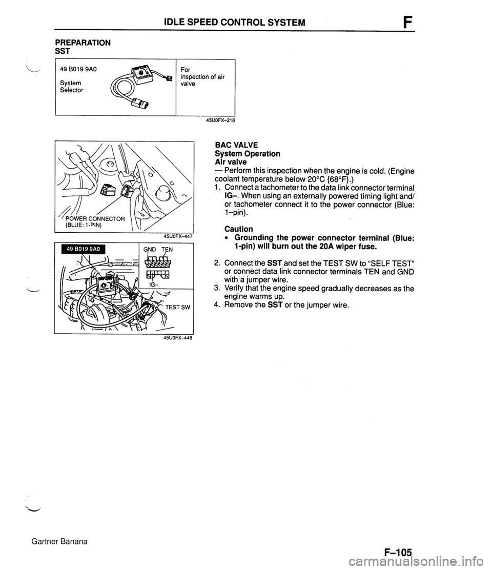
IDLE SPEED CONTROL SYSTEM PREPARATION SST I 'L 49 801 9 9AO For inspection of air System valve Selector BAC VALVE System Operation Air valve - Perform this inspection when the engine is cold. (Engine coolant temperature below 20°C {68OF).) 1. Connect a tachometer to the data link connector terminal IG-. When using an externally powered timing light and/ or tachometer connect it to the power connector (Blue: 1 -pin). Caution Grounding the power connector terminal (Blue: 1-pin) will burn out the 20A wiper fuse. 2. Connect the SST and set the TEST SW to "SELF TEST" or connect data link connector terminals TEN and GND with a jumper wire. 3. Verify that the engine speed gradually decreases as the engine warms up. 4. Remove the SST or the jumper wire. Gartner Banana