warning light MAZDA MX-5 1997 Factory Owner's Manual
[x] Cancel search | Manufacturer: MAZDA, Model Year: 1997, Model line: MX-5, Model: MAZDA MX-5 1997Pages: 514, PDF Size: 17.89 MB
Page 100 of 514
929
1. Depress brake pedal several times. Depress parking brake pedal several times with a force of 44 lbs. (20
kg). If stroke is 5-7 notches, parking brake is properly adjusted. If stroke is not 5-7 notches, rotate
adjusting nut, located under parking brake pedal, until stroke is within specification.
2. Ensure rear brakes do not drag. Ensure parking brake warning light illuminates when brake pedal is
depressed one notch.
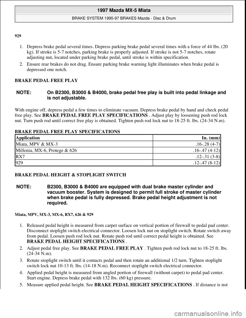
BRAKE PEDAL FREE PLAY
With engine off, depress pedal a few times to eliminate vacuum. Depress brake pedal by hand and check pedal
free play. See BRAKE PEDAL FREE PLAY SPECIFICATIONS
. Adjust play by loosening push rod lock
nut. Turn push rod until correct free play is obtained. Tighten push rod lock nut to 18-25 ft. lbs. (24-34 N.m).
BRAKE PEDAL FREE PLAY SPECIFICATIONS
BRAKE PEDAL HEIGHT & STOPLIGHT SWITCH
Miata, MPV, MX-3, MX-6, RX7, 626 & 929
1. Released pedal height is measured from carpet surface on vertical portion of firewall to pedal pad center.
Disconnect stoplight switch electrical connector. Loosen lock nut on stoplight switch. Rotate switch away
from pedal. Loosen push rod lock nut. Rotate push rod until correct pedal height is obtained. See
BRAKE PEDAL HEIGHT SPECIFICATIONS
.
2. Adjust pedal free play. See BRAKE PEDAL FREE PLAY
. Tighten push rod lock nut to 18-25 ft. lbs.
(24-34 N.m).
3. Rotate stoplight switch until it contacts pedal and then rotate an additional 1/2 turn. Tighten stoplight
switch lock nut 10-13 ft. lbs. (14-18 N.m). Reconnect stoplight switch electrical connector.
4. Applied pedal height is measured from angled portion of firewall (without carpet) to pedal pad center.
Start engine. Depress brake pedal with 132 lbs. (60 kg) pressure.
5. Measure applied pedal hei
ght. See BRAKE PEDAL HEIGHT SPECIFICATIONS . If distance is not NOTE: On B2300, B3000 & B4000, brake pedal free play is built into pedal linkage and
is not adjustable.
ApplicationIn. (mm)
Miata, MPV & MX-3.16-.28 (4-7)
Millenia, MX-6, Protege & 626.16-.47 (4-12)
RX7.12-.31 (3-8)
929.12-.47 (8-12)
NOTE: B2300, B3000 & B4000 are equipped with dual brake master cylinder and
vacuum booster. System is designed to permit full stroke of master cylinder
when brake pedal is fully depressed. Brake pedal height adjustment is not
required.
1997 Mazda MX-5 Miata
BRAKE SYSTEM 1995-97 BRAKES Mazda - Disc & Drum
Microsoft
Sunday, July 05, 2009 1:51:02 PMPage 6 © 2005 Mitchell Repair Information Company, LLC.
Page 208 of 514
Remove rear seat cushions. Disconnect fuel pump connector. Start engine and allow to stall. After engine stalls,
attempt to restart engine to ensure no residual pressure exists. Turn ignition off and reconnect fuel pump
connector. When disconnecting fuel hoses, cover connection with shop rag to catch fuel leakage. To avoid
excessive cranking after servicing, prime fuel system before starting engine.
Priming System
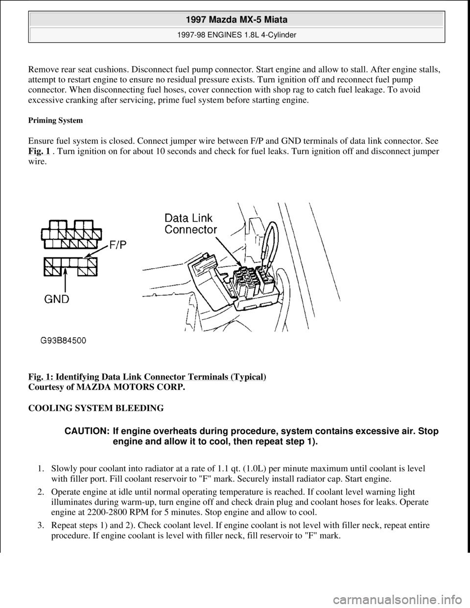
Ensure fuel system is closed. Connect jumper wire between F/P and GND terminals of data link connector. See
Fig. 1
. Turn ignition on for about 10 seconds and check for fuel leaks. Turn ignition off and disconnect jumper
wire.
Fig. 1: Identifying Data Link Connector Terminals (Typical)
Courtesy of MAZDA MOTORS CORP.
COOLING SYSTEM BLEEDING
1. Slowly pour coolant into radiator at a rate of 1.1 qt. (1.0L) per minute maximum until coolant is level
with filler port. Fill coolant reservoir to "F" mark. Securely install radiator cap. Start engine.
2. Operate engine at idle until normal operating temperature is reached. If coolant level warning light
illuminates during warm-up, turn engine off and check drain plug and coolant hoses for leaks. Operate
engine at 2200-2800 RPM for 5 minutes. Stop engine and allow to cool.
3. Repeat steps 1) and 2). Check coolant level. If engine coolant is not level with filler neck, repeat entire
procedure. If engine coolant is level with filler neck, fill reservoir to "F" mark.
CAUTION: If engine overheats during procedure, system contains excessive air. Stop
engine and allow it to cool, then repeat step 1).
1997 Mazda MX-5 Miata
1997-98 ENGINES 1.8L 4-Cylinder
Microsoft
Sunday, July 05, 2009 1:55:15 PMPage 2 © 2005 Mitchell Repair Information Company, LLC.
Page 326 of 514
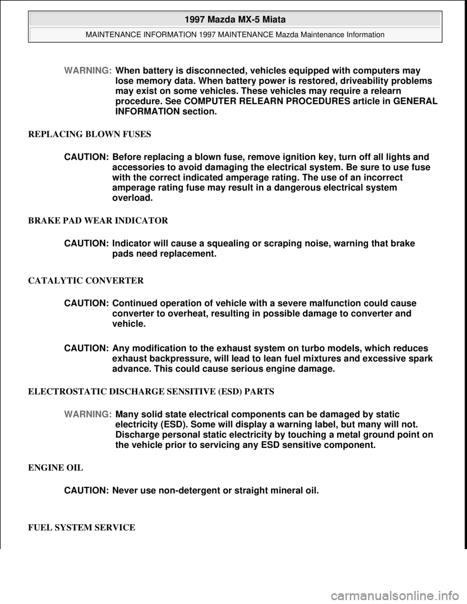
REPLACING BLOWN FUSES
BRAKE PAD WEAR INDICATOR
CATALYTIC CONVERTER
ELECTROSTATIC DISCHARGE SENSITIVE (ESD) PARTS
ENGINE OIL
FUEL SYSTEM SERVICE WARNING:When battery is disconnected, vehicles equipped with computers may
lose memory data. When battery power is restored, driveability problems
may exist on some vehicles. These vehicles may require a relearn
procedure. See COMPUTER RELEARN PROCEDURES article in GENERAL
INFORMATION section.
CAUTION: Before replacing a blown fuse, remove ignition key, turn off all lights and
accessories to avoid damaging the electrical system. Be sure to use fuse
with the correct indicated amperage rating. The use of an incorrect
amperage rating fuse may result in a dangerous electrical system
overload.
CAUTION: Indicator will cause a squealing or scraping noise, warning that brake
pads need replacement.
CAUTION: Continued operation of vehicle with a severe malfunction could cause
converter to overheat, resulting in possible damage to converter and
vehicle.
CAUTION: Any modification to the exhaust system on turbo models, which reduces
exhaust backpressure, will lead to lean fuel mixtures and excessive spark
advance. This could cause serious engine damage.
WARNING:Many solid state electrical components can be damaged by static
electricity (ESD). Some will display a warning label, but many will not.
Discharge personal static electricity by touching a metal ground point on
the vehicle prior to servicing any ESD sensitive component.
CAUTION: Never use non-detergent or straight mineral oil.
1997 Mazda MX-5 Miata
MAINTENANCE INFORMATION 1997 MAINTENANCE Mazda Maintenance Information
Microsoft
Sunday, July 05, 2009 1:41:19 PMPage 6 © 2005 Mitchell Repair Information Company, LLC.
Page 327 of 514
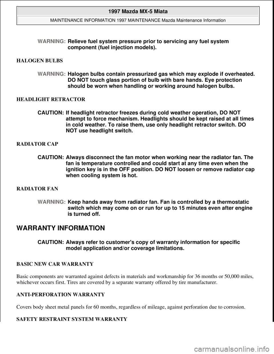
HALOGEN BULBS
HEADLIGHT RETRACTOR
RADIATOR CAP
RADIATOR FAN
WARRANTY INFORMATION
BASIC NEW CAR WARRANTY
Basic components are warranted against defects in materials and workmanship for 36 months or 50,000 miles,
whichever occurs first. Tires are covered by a separate warranty offered by tire manufacturer.
ANTI-PERFORATION WARRANTY
Covers body sheet metal panels for 60 months, regardless of mileage, against perforation due to corrosion.
SAFETY RESTRAINT SYSTEM WARRANTY WARNING:Relieve fuel system pressure prior to servicing any fuel system
component (fuel injection models).
WARNING:Halogen bulbs contain pressurized gas which may explode if overheated.
DO NOT touch glass portion of bulb with bare hands. Eye protection
should be worn when handling or working around halogen bulbs.
CAUTION: If headlight retractor freezes during cold weather operation, DO NOT
attempt to force mechanism. Headlights should be kept raised at all times
in cold weather. To raise them, use only headlight retractor switch. DO
NOT use headlight switch.
CAUTION: Always disconnect the fan motor when working near the radiator fan. The
fan is temperature controlled and could start at any time even when the
ignition key is in the OFF position. DO NOT loosen or remove radiator cap
when cooling system is hot.
WARNING:Keep hands away from radiator fan. Fan is controlled by a thermostatic
switch which may come on or run for up to 15 minutes even after engine
is turned off.
CAUTION: Always refer to customer's copy of warranty information for specific
model application and/or coverage limitations.
1997 Mazda MX-5 Miata
MAINTENANCE INFORMATION 1997 MAINTENANCE Mazda Maintenance Information
Microsoft
Sunday, July 05, 2009 1:41:19 PMPage 7 © 2005 Mitchell Repair Information Company, LLC.
Page 329 of 514
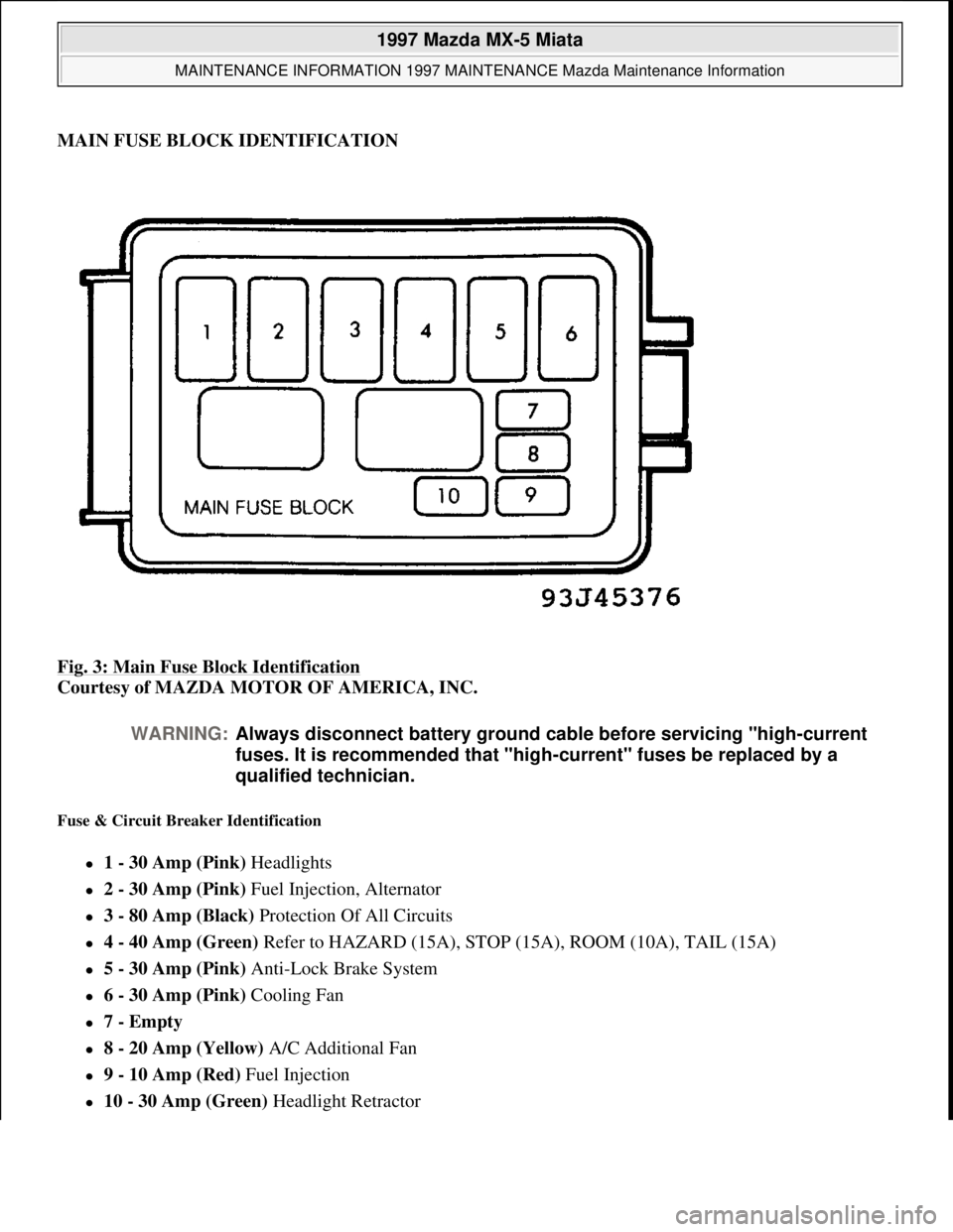
MAIN FUSE BLOCK IDENTIFICATION
Fig. 3: Main Fuse Block Identification
Courtesy of MAZDA MOTOR OF AMERICA, INC.
Fuse & Circuit Breaker Identification
1 - 30 Amp (Pink) Headlights
2 - 30 Amp (Pink) Fuel Injection, Alternator
3 - 80 Amp (Black) Protection Of All Circuits
4 - 40 Amp (Green) Refer to HAZARD (15A), STOP (15A), ROOM (10A), TAIL (15A)
5 - 30 Amp (Pink) Anti-Lock Brake System
6 - 30 Amp (Pink) Cooling Fan
7 - Empty
8 - 20 Amp (Yellow) A/C Additional Fan
9 - 10 Amp (Red) Fuel Injection
10 - 30 Amp (Green) Headlight Retractor
WARNING:Always disconnect battery ground cable before servicing "high-current
fuses. It is recommended that "high-current" fuses be replaced by a
qualified technician.
1997 Mazda MX-5 Miata
MAINTENANCE INFORMATION 1997 MAINTENANCE Mazda Maintenance Information
Microsoft
Sunday, July 05, 2009 1:41:19 PMPage 9 © 2005 Mitchell Repair Information Company, LLC.
Page 331 of 514
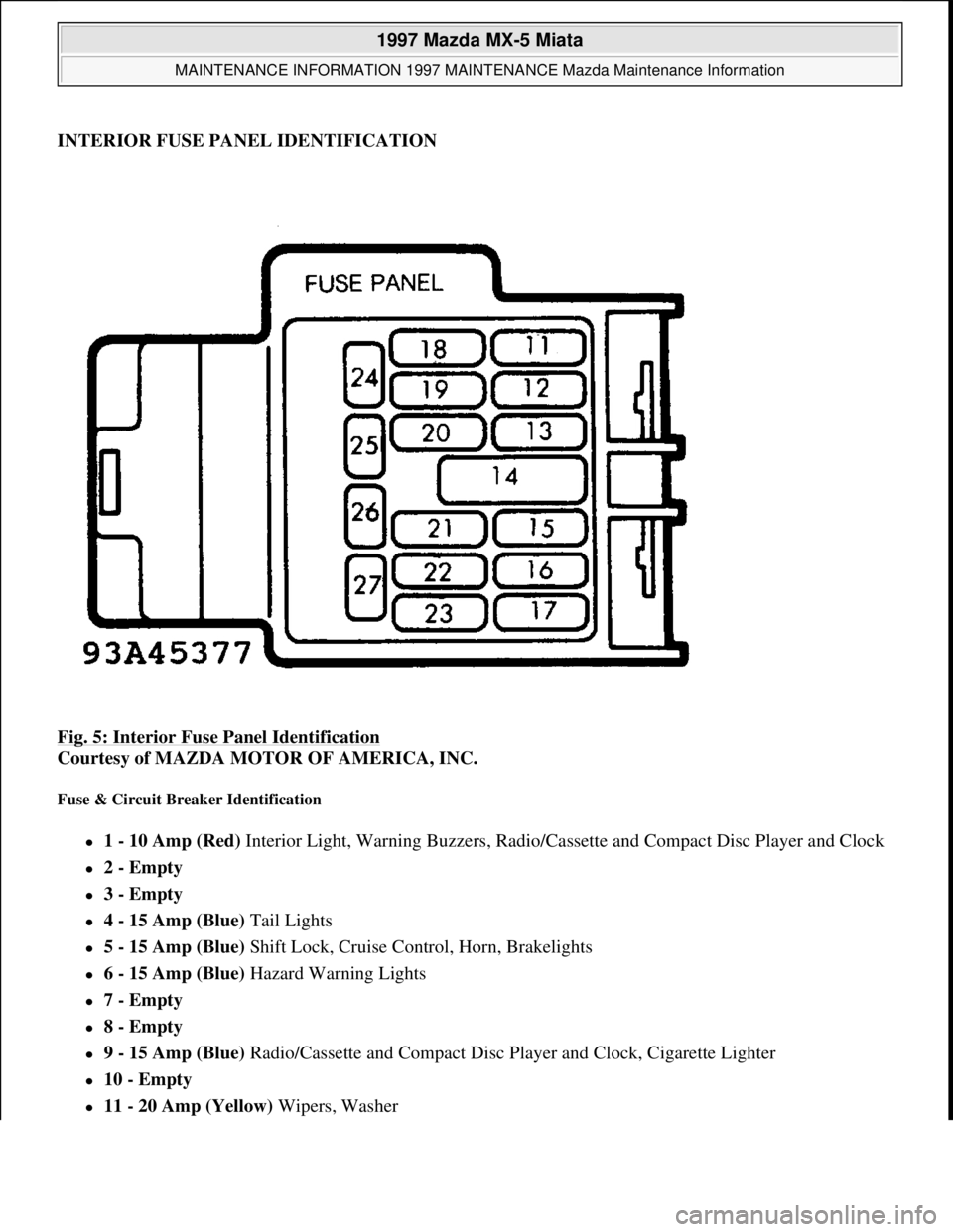
INTERIOR FUSE PANEL IDENTIFICATION
Fig. 5: Interior Fuse Panel Identification
Courtesy of MAZDA MOTOR OF AMERICA, INC.
Fuse & Circuit Breaker Identification
1 - 10 Amp (Red) Interior Light, Warning Buzzers, Radio/Cassette and Compact Disc Player and Clock
2 - Empty
3 - Empty
4 - 15 Amp (Blue) Tail Lights
5 - 15 Amp (Blue) Shift Lock, Cruise Control, Horn, Brakelights
6 - 15 Amp (Blue) Hazard Warning Lights
7 - Empty
8 - Empty
9 - 15 Amp (Blue) Radio/Cassette and Compact Disc Player and Clock, Cigarette Lighter
10 - Empty
11 - 20 Amp (Yellow) Wipers, Washer
1997 Mazda MX-5 Miata
MAINTENANCE INFORMATION 1997 MAINTENANCE Mazda Maintenance Information
Microsoft
Sunday, July 05, 2009 1:41:19 PMPage 11 © 2005 Mitchell Repair Information Company, LLC.
Page 332 of 514
12 - 30 Amp (Green) Power Windows
13 - Empty
14 - Empty 15 - 15 Amp (Blue) Gauges, Warning Lights, Turn-Signal Lights, Cruise Control
16 - 15 Amp (Blue) Cooling Fan
17 - 30 Amp (Pink) Heater
18 - Empty
19 - Empty
20 - 10 Amp Defog (Some Models)
21 - 10 Amp Antenna (Some Models)
22 - Empty
1997 Mazda MX-5 Miata
MAINTENANCE INFORMATION 1997 MAINTENANCE Mazda Maintenance Information
Microsoft
Sunday, July 05, 2009 1:41:19 PMPage 12 © 2005 Mitchell Repair Information Company, LLC.
Page 399 of 514
STEERING COLUMN
1995-97 STEERING Mazda Motors Corp. - Steering Columns
DESCRIPTION & OPERATION
Steering columns are designed to be collapsible upon impact. The steering column consists of solid steering
shaft with a lower joint assembly. Some models are equipped with tilt steering. Turn signal, headlight, ignition
and windshield washer/wiper switches are mounted on column. Switches can be serviced by removing steering
wheel and column covers. All models are equipped with air bag restraint system consisting of an driver air bag
module, passenger air bag module (except 1995 MPV and 1995 Protege) and clockspring connector assembly
located in the steering column.
SYSTEM OPERATION CHECK
1. Turn ignition switch to ON or START position. AIR BAG warning light in instrument cluster should
illuminate for about 4-8 seconds, and then turn off. This indicates air bag system is functioning properly.
2. If any of the following conditions exists, air bag system is malfunctioning and requires servicing.
AIR BAG warning light does not illuminate as specified.
AIR BAG warning light remains illuminated for more than 8 seconds.
AIR BAG warning light illuminates while driving.
3. If air bag system components are replaced for any reason, air bag system must be checked for proper
function after repair. Repeat step 1). If AIR BAG warning light does not illuminate as specified, air bag
system is malfunctioning and servicing is required. See AIR BAG RESTRAINT SYSTEM article.
SERVICE PRECAUTIONS
Observe the following precautions when servicing air bag system.
Disable air bag system before servicing any air bag system or steering column component. See AIR BAG
DISABLING & ACTIVATING .
After disabling air bag system, wait at least one minute before servicing. Air bag system voltage is
maintained for approximately one minute after system is disabled. Failure to wait one minute before
servicing system may cause accidental air bag deployment and possible personal injury.
Obtain radio code number from customer and deactivate radio anti-theft function (if equipped) before
disconnecting battery.
Because of the critical operation requirements of system, DO NOT service any air bag system
component. Repairs are made by replacement only.
DO NOT use an ohmmeter to check resistance of air bag module, as it may cause air bag deployment.
When carrying a live (undeployed) air bag module, ensure trim cover is pointed away from your body. WARNING:To avoid injury from accidental air bag deployment, read and carefully
follow all WARNINGS and SERVICE PRECAUTIONS
.
1997 Mazda MX-5 Miata
STEERING COLUMN 1995-97 STEERING Mazda Motors Corp. - Steering Columns
1997 Mazda MX-5 Miata
STEERING COLUMN 1995-97 STEERING Mazda Motors Corp. - Steering Columns
Microsoft
Sunday, July 05, 2009 1:40:02 PMPage 1 © 2005 Mitchell Repair Information Company, LLC.
Microsoft
Sunday, July 05, 2009 1:40:07 PMPage 1 © 2005 Mitchell Repair Information Company, LLC.
Page 400 of 514
This minimizes chance of injury in the event of accidental air bag deployment.
When placing a live air bag module on any surface, always face trim cover upward to reduce motion of
module if it is accidentally deployed.
If an open circuit is present, replace entire wiring harness. DO NOT attempt to repair wire(s).
Air bag system clockspring MUST be aligned in neutral position, since its rotation ability is limited. DO
NOT turn steering wheel or column after removal of steering gear.
A double-lock mechanism is used on clockspring connectors. DO NOT use excessive force when
disconnecting connectors, as damage to connector may occur.
AIR BAG DISABLING & ACTIVATING
DISABLING SYSTEM (MIATA, MILLENIA, MPV, MX-6, PROTEGE & 626)
1. Obtain radio code from customer and deactivate audio anti-theft function (if equipped). Turn ignition off.
Disconnect and shield negative battery cable. Wait at least one minute for back-up power supply to be
depleted. Remove lower cover panel(s) below left side of instrument panel.
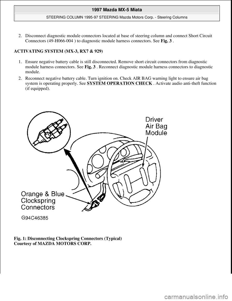
2. On MPV, remove lower steering column shroud. On all models, disconnect Orange and Blue clockspring
connectors for driver air bag module. See Fig. 1
. On all models except 1995 Protege and 1995 MPV,
remove glove box compartment. Disconnect Orange and Blue connectors for passenger air bag module.
See Fig. 2
.
ACTIVATING SYSTEM (MIATA, MILLENIA, MPV, MX-6, PROTEGE & 626)
1. Ensure negative battery cable is still disconnected. On all models except 1995 Protege and 1995 MPV,
reconnect Orange and Blue connector for passenger air bag module. Install glove box compartment.
2. On all models, reconnect Orange and Blue clockspring connectors for driver air bag module. Install lower
cover panel(s). On MPV, install lower steering column shroud. On all models, reconnect negative battery
cable.
3. Turn ignition on. Check AIR BAG warning light to ensure air bag system is operating properly. See
SYSTEM OPERATION CHECK
. Activate audio anti-theft function (if equipped).
DISABLING SYSTEM (MX-3, RX7 & 929)
1. Obtain radio code from customer and deactivate audio anti-theft function. Turn ignition off. Disconnect
and shield ne
gative battery cable. Wait at least one minute for back-up power supply to be depleted. WARNING:Wait about one minute after disabling air bag system before servicing. Air
bag system voltage is maintained for about one minute after system is
disabled. Failure to wait one minute before servicing system may cause
accidental air bag deployment and possible personal injury.
CAUTION: When battery is disconnected, vehicle computer and memory systems
may lose memory data. Driveability problems may exist until computer
systems have completed a relearn cycle.
1997 Mazda MX-5 Miata
STEERING COLUMN 1995-97 STEERING Mazda Motors Corp. - Steering Columns
Microsoft
Sunday, July 05, 2009 1:40:02 PMPage 2 © 2005 Mitchell Repair Information Company, LLC.
Page 401 of 514
2. Disconnect diagnostic module connectors located at base of steering column and connect Short Circuit
Connectors (49-H066-004 ) to diagnostic module harness connectors. See Fig. 3
.
ACTIVATING SYSTEM (MX-3, RX7 & 929)
1. Ensure negative battery cable is still disconnected. Remove short circuit connectors from diagnostic
module harness connectors. See Fig. 3
. Reconnect diagnostic module harness connectors to diagnostic
module.
2. Reconnect negative battery cable. Turn ignition on. Check AIR BAG warning light to ensure air bag
system is operating properly. See SYSTEM OPERATION CHECK
. Activate audio anti-theft function
(if equipped).
Fig. 1: Disconnecting Clockspring Connectors (Typical)
Courtesy of MAZDA MOTORS CORP.
1997 Mazda MX-5 Miata
STEERING COLUMN 1995-97 STEERING Mazda Motors Corp. - Steering Columns
Microsoft
Sunday, July 05, 2009 1:40:02 PMPage 3 © 2005 Mitchell Repair Information Company, LLC.