torque MAZDA MX-5 1997 Factory Manual PDF
[x] Cancel search | Manufacturer: MAZDA, Model Year: 1997, Model line: MX-5, Model: MAZDA MX-5 1997Pages: 514, PDF Size: 17.89 MB
Page 368 of 514
1997, 1999-2000 SUSPENSION
Rear - Miata
DESCRIPTION
Rear suspension consists of spring over shock, crossmember, upper and lower arms, and stabilizer bar with
control link. Upper and lower arms attach to crossmember and knuckle. A stabilizer bar with control link is
mounted to lower arm and crossmember. Rear wheel alignment is adjusted by turning adjusting cams on lower
arm. Upper coil over shock mount plate has been redesigned for 1999-2000. New design incorporates a
urethane bumper and improves ride and cornering.
ADJUSTMENTS & INSPECTION
WHEEL ALIGNMENT SPECIFICATIONS & PROCEDURES
WHEEL BEARING ADJUSTMENT
Raise and support vehicle. Remove rear wheel assembly. Remove caliper assembly and ABS wheel speed
sensor. Remove brake rotor. Attach dial indicator to axle hub and measure bearing play. Check bearing axial
play by rocking hub assembly by hand. Maximum bearing play is .002" (.05 mm). If play exceeds specification,
check drive axle lock nut torque or replace wheel bearing. See TORQUE SPECIFICATIONS
.
REMOVAL & INSTALLATION
WHEEL BEARING
Removal
1. Raise and support vehicle. Remove rear wheel assembly. Remove drive axle lock nut. Remove brake
caliper assembly and ABS wheel speed sensor, and wire aside. Remove screws and rotor. Remove ABS
speed sensor bracket. Remove knuckle assembly from upper and lower arms.
2. Using Handle (49-G030-102), Installer (49-G030-727) and Puller (49-F026-103), remove hub from
knuckle. Remove snap ring from knuckle. Using handle, installer and Puller (49-0636-145), remove
wheel bearing inner race from hub. Remove wheel bearing outer race from knuckle using Handle (49-
G030-797), Puller (49-F026-103) and Adapter (49-F027-005).
Inspection
Check wheel hub and knuckle for cracks and damage. Check dust cover for deformation. Check bearing for
excessive wear or seizure. Replace components as necessary.
Installation
NOTE: See SPECIFICATIONS & PROCEDURES article in WHEEL ALIGNMENT.
1997 Mazda MX-5 Miata
1997, 1999-2000 SUSPENSION Rear - Miata
1997 Mazda MX-5 Miata
1997, 1999-2000 SUSPENSION Rear - Miata
Microsoft
Sunday, July 05, 2009 1:38:49 PMPage 1 © 2005 Mitchell Repair Information Company, LLC.
Microsoft
Sunday, July 05, 2009 1:38:53 PMPage 1 © 2005 Mitchell Repair Information Company, LLC.
Page 369 of 514
Press new wheel bearing into knuckle using Handle (49-G030-797), Installer (49-F027-007) and Adapter (49-
F027-009). Press hub into knuckle using adapter. To install, reverse removal procedure. Tighten drive axle lock
nut to specification. See TORQUE SPECIFICATIONS
. Stake drive axle lock nut. Check axial play. See
WHEEL BEARING ADJUSTMENT
.
SHOCK ASSEMBLY
Removal & Disassembly
1. Raise vehicle and remove fuel tank filler pipe protector (1997). Remove rear wheel assembly. Remove
stabilizer bar nut and bolt from lower control arm. Remove 2 upper shock mount-to-body nuts. Remove
lower shock bolt. Lower arms, and remove shock assembly.
2. Clamp shock securely in soft-jaw vise. Compress coil spring. Remove lock nut and washer. Remove
remaining components and note order for reassembly.
Inspection
Check shock for leaks or abnormal noise. Inspect components for wear or damage. Check for loose installation
of bolts and nuts. Replace components as necessary.
Reassembly (1997)
To reassemble, reverse disassembly procedure. To install, reverse removal procedure. Ensure coil spring is
seated in upper and lower seats. See Fig. 1
. Tighten piston rod nut. See TORQUE SPECIFICATIONS. CAUTION: DO NOT lower arms excessively. This may damage brake hose.
1997 Mazda MX-5 Miata
1997, 1999-2000 SUSPENSION Rear - Miata
Microsoft
Sunday, July 05, 2009 1:38:49 PMPage 2 © 2005 Mitchell Repair Information Company, LLC.
Page 372 of 514
Installation
Reinstall shock in reverse order. Tighten nuts and bolts to specification with vehicle resting on ground and
suspension unloaded. See TORQUE SPECIFICATIONS
. Check rear wheel alignment. See
SPECIFICATIONS & PROCEDURES article in WHEEL ALIGNMENT.
LOWER ARM
Removal
Raise and support vehicle. Remove rear wheel assembly. Remove stabilizer bar control link nut and bolt. See
Fig. 3
. Remove lower shock bolt. Remove lower arm-to-crossmember bolts. Remove lower arm-to-knuckle
bolts. Remove lower arm. Inspect arm for damage, cracks and deformation. Check for damaged or worn
bushings.
Installation
To install, reverse removal procedure. Tighten all nuts/bolts to specification with vehicle resting on ground and
suspension unloaded. See TORQUE SPECIFICATIONS
. Adjust rear wheel alignment. See
SPECIFICATIONS & PROCEDURES article in WHEEL ALIGNMENT.
1997 Mazda MX-5 Miata
1997, 1999-2000 SUSPENSION Rear - Miata
Microsoft
Sunday, July 05, 2009 1:38:49 PMPage 5 © 2005 Mitchell Repair Information Company, LLC.
Page 373 of 514
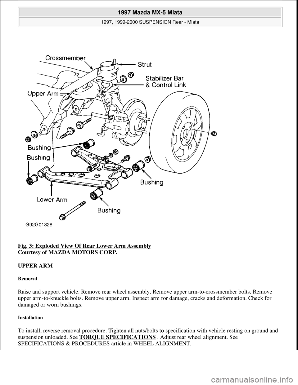
Fig. 3: Exploded View Of Rear Lower Arm Assembly
Courtesy of MAZDA MOTORS CORP.
UPPER ARM
Removal
Raise and support vehicle. Remove rear wheel assembly. Remove upper arm-to-crossmember bolts. Remove
upper arm-to-knuckle bolts. Remove upper arm. Inspect arm for damage, cracks and deformation. Check for
damaged or worn bushings.
Installation
To install, reverse removal procedure. Tighten all nuts/bolts to specification with vehicle resting on ground and
suspension unloaded. See TORQUE SPECIFICATIONS
. Adjust rear wheel alignment. See
SPECIFICATIONS & PROCEDURES article in WHEEL ALIGNMENT.
1997 Mazda MX-5 Miata
1997, 1999-2000 SUSPENSION Rear - Miata
Microsoft
Sunday, July 05, 2009 1:38:49 PMPage 6 © 2005 Mitchell Repair Information Company, LLC.
Page 374 of 514
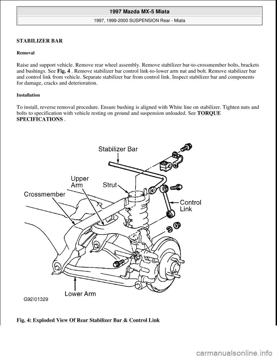
STABILIZER BAR
Removal
Raise and support vehicle. Remove rear wheel assembly. Remove stabilizer bar-to-crossmember bolts, brackets
and bushings. See Fig. 4
. Remove stabilizer bar control link-to-lower arm nut and bolt. Remove stabilizer bar
and control link from vehicle. Separate stabilizer bar from control link. Inspect stabilizer bar and components
for damage, cracks and deterioration.
Installation
To install, reverse removal procedure. Ensure bushing is aligned with White line on stabilizer. Tighten nuts and
bolts to specification with vehicle resting on ground and suspension unloaded. See TORQUE
SPECIFICATIONS .
Fig. 4: Exploded View Of Rear Stabilizer Bar & Control Link
1997 Mazda MX-5 Miata
1997, 1999-2000 SUSPENSION Rear - Miata
Microsoft
Sunday, July 05, 2009 1:38:49 PMPage 7 © 2005 Mitchell Repair Information Company, LLC.
Page 375 of 514
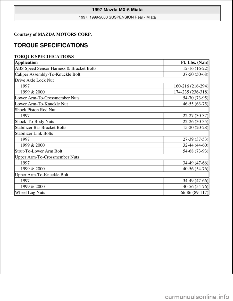
Courtesy of MAZDA MOTORS CORP.
TORQUE SPECIFICATIONS
TORQUE SPECIFICATIONS
ApplicationFt. Lbs. (N.m)
ABS Speed Sensor Harness & Bracket Bolts12-16 (16-22)
Caliper Assembly-To-Knuckle Bolt37-50 (50-68)
Drive Axle Lock Nut
1997160-216 (216-294)
1999 & 2000174-235 (236-318)
Lower Arm-To-Crossmember Nuts54-70 (73-95)
Lower Arm-To-Knuckle Nut46-55 (63-75)
Shock Piston Rod Nut
199722-27 (30-37)
Shock-To-Body Nuts22-26 (30-35)
Stabilizer Bar Bracket Bolts15-20 (20-28)
Stabilizer Link Bolts
199727-39 (37-53)
1999 & 200032-44 (44-60)
Strut-To-Lower Arm Bolt54-68 (73-93)
Upper Arm-To-Crossmember Nuts
199734-49 (47-66)
1999 & 200040-56 (54-76)
Upper Arm-To-Knuckle Bolt
199734-49 (47-66)
1999 & 200040-56 (54-76)
Wheel Lug Nuts66-86 (89-117)
1997 Mazda MX-5 Miata
1997, 1999-2000 SUSPENSION Rear - Miata
Microsoft
Sunday, July 05, 2009 1:38:49 PMPage 8 © 2005 Mitchell Repair Information Company, LLC.
Page 383 of 514
FIELD WINDING TEST
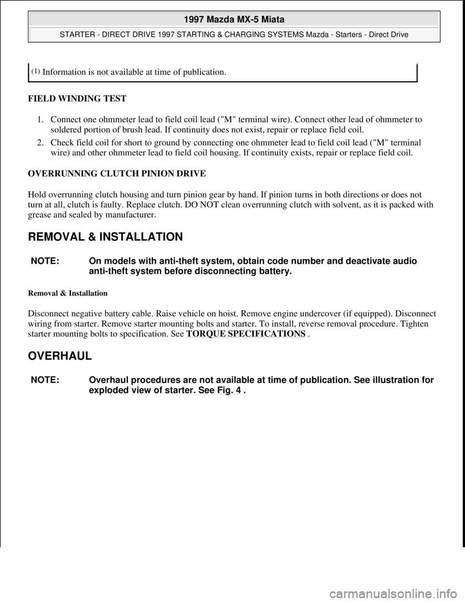
1. Connect one ohmmeter lead to field coil lead ("M" terminal wire). Connect other lead of ohmmeter to
soldered portion of brush lead. If continuity does not exist, repair or replace field coil.
2. Check field coil for short to ground by connecting one ohmmeter lead to field coil lead ("M" terminal
wire) and other ohmmeter lead to field coil housing. If continuity exists, repair or replace field coil.
OVERRUNNING CLUTCH PINION DRIVE
Hold overrunning clutch housing and turn pinion gear by hand. If pinion turns in both directions or does not
turn at all, clutch is faulty. Replace clutch. DO NOT clean overrunning clutch with solvent, as it is packed with
grease and sealed by manufacturer.
REMOVAL & INSTALLATION
Removal & Installation
Disconnect negative battery cable. Raise vehicle on hoist. Remove engine undercover (if equipped). Disconnect
wiring from starter. Remove starter mounting bolts and starter. To install, reverse removal procedure. Tighten
starter mounting bolts to specification. See TORQUE SPECIFICATIONS
.
OVERHAUL
(1)Information is not available at time of publication.
NOTE: On models with anti-theft system, obtain code number and deactivate audio
anti-theft system before disconnecting battery.
NOTE: Overhaul procedures are not available at time of publication. See illustration for
exploded view of starter. See Fig. 4
.
1997 Mazda MX-5 Miata
STARTER - DIRECT DRIVE 1997 STARTING & CHARGING SYSTEMS Mazda - Starters - Direct Drive
Microsoft
Sunday, July 05, 2009 1:56:16 PMPage 8 © 2005 Mitchell Repair Information Company, LLC.
Page 384 of 514
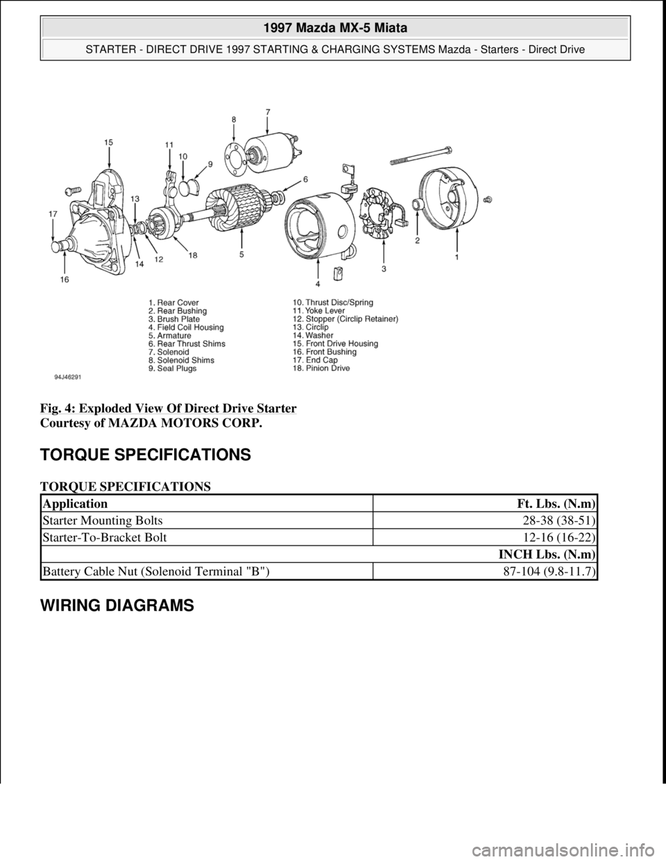
Fig. 4: Exploded View Of Direct Drive Starter
Courtesy of MAZDA MOTORS CORP.
TORQUE SPECIFICATIONS
TORQUE SPECIFICATIONS
WIRING DIAGRAMS
ApplicationFt. Lbs. (N.m)
Starter Mounting Bolts28-38 (38-51)
Starter-To-Bracket Bolt12-16 (16-22)
INCH Lbs. (N.m)
Battery Cable Nut (Solenoid Terminal "B")87-104 (9.8-11.7)
1997 Mazda MX-5 Miata
STARTER - DIRECT DRIVE 1997 STARTING & CHARGING SYSTEMS Mazda - Starters - Direct Drive
Microsoft
Sunday, July 05, 2009 1:56:16 PMPage 9 © 2005 Mitchell Repair Information Company, LLC.
Page 395 of 514
FIELD WINDING TEST
1. Connect one ohmmeter lead to field coil lead ("M" terminal wire). Connect other lead of ohmmeter to
soldered portion of brush lead. If continuity does not exist, repair or replace field coil.
2. Check field coil for short to ground by connecting one ohmmeter lead to field coil lead ("M" terminal
wire) and other ohmmeter lead to field coil housing. If continuity exists, repair or replace field coil.
OVERRUNNING CLUTCH PINION DRIVE
Hold overrunning clutch housing and turn pinion gear by hand. If pinion turns in both directions or does not
turn at all, clutch is faulty. Replace clutch. DO NOT clean overrunning clutch with solvent, as it is packed with
grease and sealed by manufacturer.
REMOVAL & INSTALLATION
Removal & Installation
Disconnect negative battery cable. Raise vehicle on hoist. Remove engine undercover (if equipped). Disconnect
wiring from starter. Remove starter mounting bolts and starter. To install, reverse removal procedure. Tighten
starter mounting bolts to specification. See TORQUE SPECIFICATIONS
.
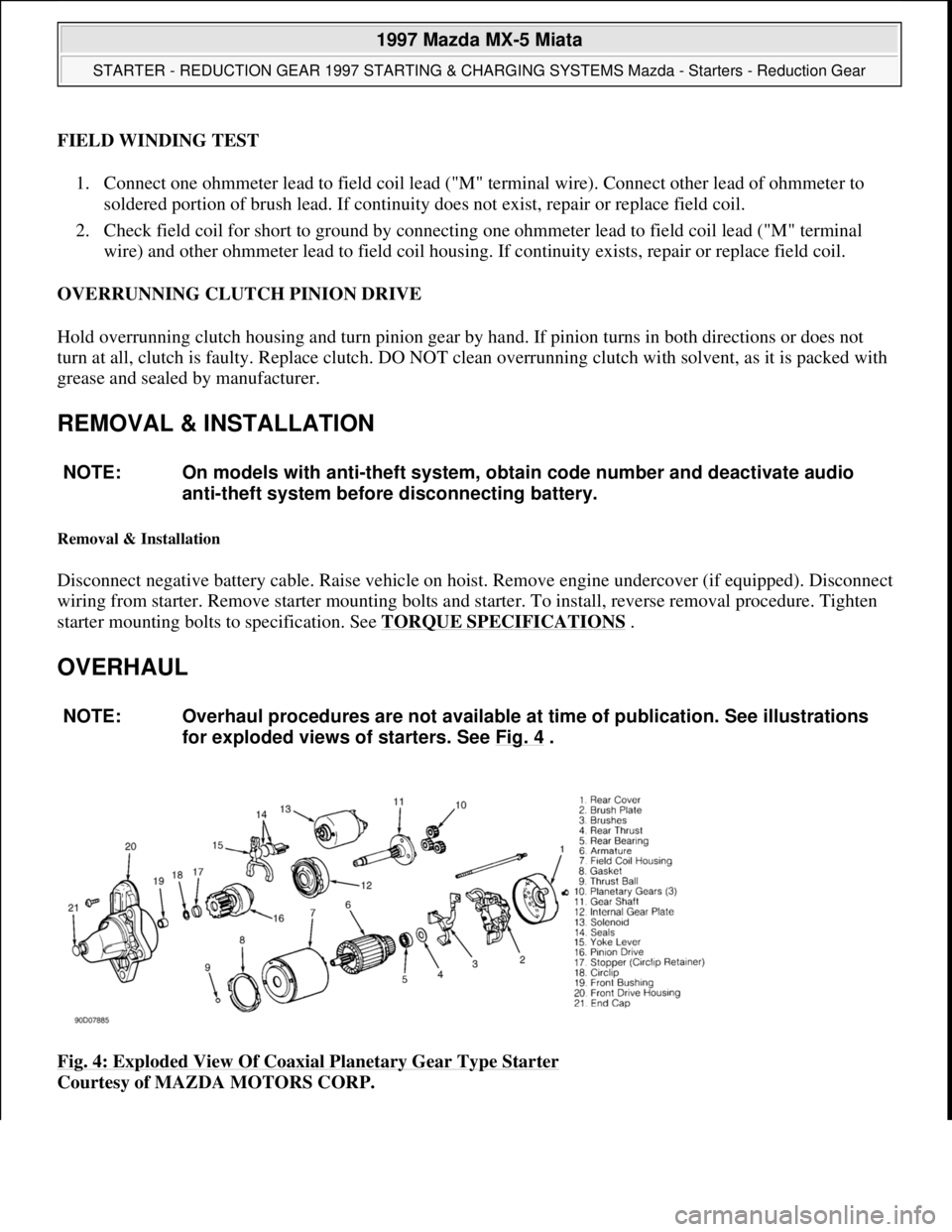
OVERHAUL
Fig. 4: Exploded View Of Coaxial Planetary Gear Type Starter
Courtesy of MAZDA MOTORS CORP. NOTE: On models with anti-theft system, obtain code number and deactivate audio
anti-theft system before disconnecting battery.
NOTE: Overhaul procedures are not available at time of publication. See illustrations
for exploded views of starters. See Fig. 4
.
1997 Mazda MX-5 Miata
STARTER - REDUCTION GEAR 1997 STARTING & CHARGING SYSTEMS Mazda - Starters - Reduction Gear
Microsoft
Sunday, July 05, 2009 1:56:43 PMPage 9 © 2005 Mitchell Repair Information Company, LLC.
Page 396 of 514
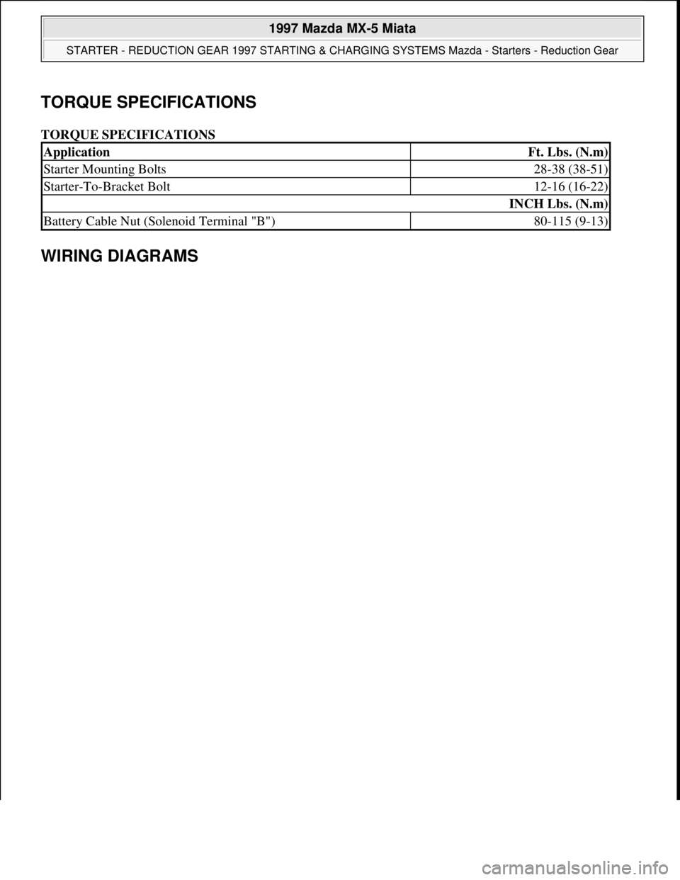
TORQUE SPECIFICATIONS
TORQUE SPECIFICATIONS
WIRING DIAGRAMS
ApplicationFt. Lbs. (N.m)
Starter Mounting Bolts28-38 (38-51)
Starter-To-Bracket Bolt12-16 (16-22)
INCH Lbs. (N.m)
Battery Cable Nut (Solenoid Terminal "B")80-115 (9-13)
1997 Mazda MX-5 Miata
STARTER - REDUCTION GEAR 1997 STARTING & CHARGING SYSTEMS Mazda - Starters - Reduction Gear
Microsoft
Sunday, July 05, 2009 1:56:43 PMPage 10 © 2005 Mitchell Repair Information Company, LLC.