ignition MAZDA PROTEGE 1992 Workshop Manual
[x] Cancel search | Manufacturer: MAZDA, Model Year: 1992, Model line: PROTEGE, Model: MAZDA PROTEGE 1992Pages: 1164, PDF Size: 81.9 MB
Page 765 of 1164

POWER WINDOW SYSTEM S
Power window system does not operate
(All doors)
I
NG
Check POWER WIND 30A fuse - Repair harness and replace fuse
I
1 OK
Turn ignition switch ON
Check for battery voltage at terminal-wire (B/W) of main NG
power window switch connector Repair harness (Fuse box-Main power window switch)
I
OK
Disconnect main power window switch connector;
check continuity of terminal-wire (B) to ground Repair harness (Main switch-Ground)
OK
- Check main power window switch (Refer to page S-31)
I I
23UOSX-010
Only driver side power window does not operate
( Turn ignition switch ON
Check for battery voltage at terminal-wires (R/B) and
(R/G) of main power window switch connector
UP
DOWN (R/G) wire
~ _ 1 NG -i VB: Battst’y VOltaQe,
Check main power wrndow switch (Refer to page S-31)
OK
Check for battery voltage at terminal-wires (R/B) and
(R/G) of power window motor connector OK
= Check power window motor (Refer to page S-32)
23UOSX-011
Sk29
Page 766 of 1164

POWER WINDOW SYSTEM
II
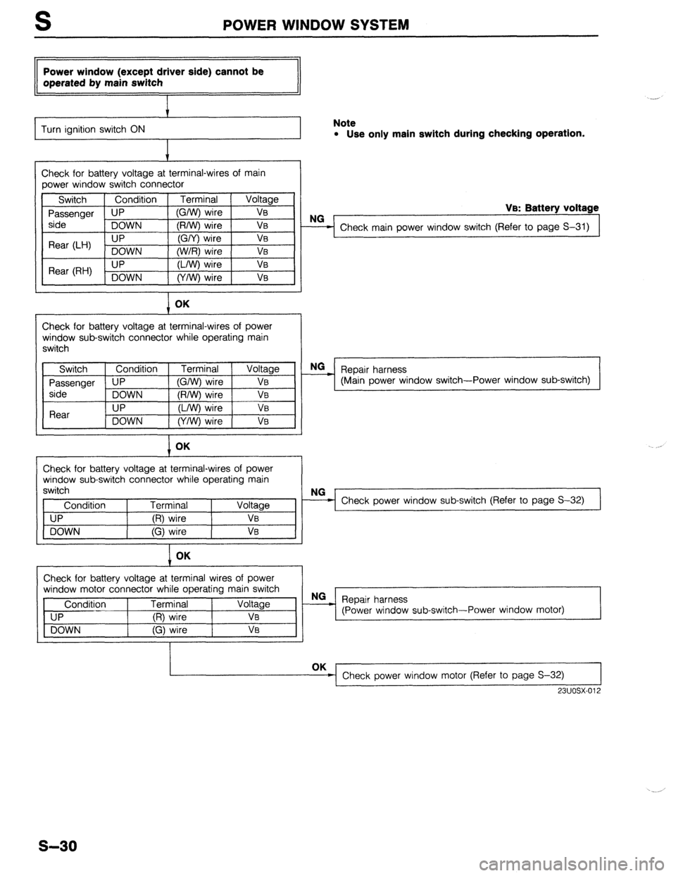
Power window (except driver side) cannot be
operated by main switch
t
Turn ignition switch ON Note l Use only main switch during checking operation.
t
Check for battery voltage at terminal-wires of main
power window switch connector
Switch Condition
Passenger UP
side
DOWN
Rear (LH) . UP
DOWN
Rear (RH) UP
DOWN Terminal Voltage
(G/W) wire Ve
(R/W) wire VB
(G/Y) wire VB
(W/R) wire VB
(L/W) wire VB
(Y/W) wire Ve
I OK
Check for battery voltage at terminal-wires of power
window sub-switch connector while operating main
switch
VB: Battery voltage
NO
- Check main power window switch (Refer to page S-31) NG
___) Repair harness
(Main power window switch-Power window sub-switch)
I OK
Check for battery voltage at terminal-wires of power
window sub-switch connector while operating main
switch
Condition Terminal
UP (R) wire VB
DOWN (G) wire VB
I Check power window sub-switch (Refer to page S-32)
1 OK
Check for battery voltage at terminal wires of power
window motor connector while operating main switch
Condition Terminal Voltage
UP (R) wire
DOWN (G) wire OK
Check power window motor (Refer to page S-32) I 23uosx-012
s-30
Page 767 of 1164

POWER WINDOW SYSTEM
Main power window switch operates, but switch
on each door does not operate power window
I Turn ignition switch ON , !
Turn main power window switch ON
Check for battery voltage at terminal-wire (B/L) of main NG _ Check power switch of main power window switch
power window switch connector (Refer to page S-31) OK
Check for battery voltage at terminal-wire (B/L) of switch 3 Repair harness
on each door (Main power window switch-Power window sub-switch) OK
Check power window sub-switch (Refer to page S-32)
23UOSX-013
I PROTEGli HATCHBACK
I
ace
i k
MAIN POWER WINDOW SWITCH
Inspection
Check for continuity between terminals of the switch with an
ohmmeter.
Power switch (ON/OFF)
ON
nl=l= PROTEGE Hatchback
a f h
9
0 0 0 0
0--O: Indicates continuity
Power window switch (Up/Down)
UP ------ o-j0 - -
o-o 00 00
OFF 000 oojo 000 000
I DOWN
0---O: Indicates continuity
s-31
Page 791 of 1164

OUTSIDE MIRROR S
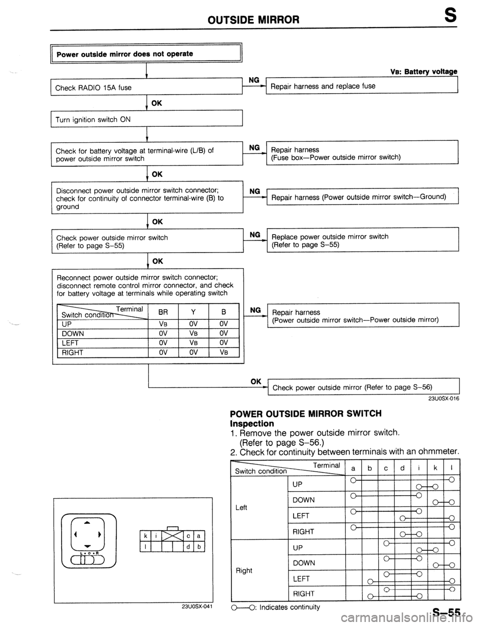
Power outside mirror does not operate
I
I VB: Battery voltage
Check RADIO 15A fuse Repair harness and replace fuse OK
Turn ignition switch ON
I.’
Check for battery voltage at terminal-wire (LIB) of NG
_ Repair harness
power outside mirror switch (Fuse box-Power outside mirror switch) OK
1
I
Disconnect power outside mirror switch connector;
check for continuity of connector terminal-wire (B) to
ground Repair harness (Power outside mirror switch-Ground)
Check power outside mirror switch
(Refer to page S-55) OK
- Replace power outside mirror switch NO
(Refer to page S-55)
Reconnect power outside mirror switch connector;
disconnect remote control mirror connector, and check
for battery voltage at terminals while operating switch
I IP
NG
_ Repair harness
(Power outside mirror switch-Power outside mirror)
VI
DOWN
LEFT
RIGHT OK
Check power outside mirror (Refer to page S-56) I I
23UOSX-016
POWER OUTSIDE MIRROR SWITCH
Inspection
1. Remove the power outside mirror switch.
(Refer to page S-56.)
2. Check for continuity between terminals with an ohmmeter.
23UOSX-04
TermIn:
-1
I I
UP 0’
LEFT 0
0
o---O: Indicates continuity
Page 804 of 1164

WINDSHIELD WIPER AND WASHER
Wiper does not operate in Lo or Hi position
(With wiper relay)’
I
Check WIPER 20A fuse
Repair harness and replace fuse
VB: Battery voltage
OK
Turn ignition switch ON
Check for battery voltage at terminal-wires (L) of wiper
relay connector NG
- Repair harness (Fuse box-Wiper relay)
I OK
Check for battery voltage at terminal-wires (W) and
(G/W) of above connector
I Replace wiper relay (Refer to Section T)
OK
Disconnect wiper switch connector;
check for battery voltage at terminal-wires (W) and
W’J) Repair harness (Wiper relay -Wiper switch)
I OK
Check for continuity of above connector terminal-wire
(B) to ground
I
Repair harness (Wiper switch-Ground) 1
1 OK
Check wiper switch (Refer to
I Replace combination switch (Refer to Section T)
1 OK
Check for battery voltage at terminal-wires (L/W) and (R)
of wiper relay connector with switch as shown NG
Replace wiper relay (Refer to Section T)
l Lo : (L/W) Ve l Hi : (R) Ve
OK
1 I
Disconnect wiper motor connector; check for battery
voltage at terminal-wires (L/W) and (R) with switch as
shown
l !-0 : (L/w) VB l Hi : (R) VB NG
= Repair harness (Wiper relay-Wiper motor)
OK
Check continuity between wiper motor body and
ground NG
= Repair ground circuit of wiper motor body
Check wiper motor (Refer to page S-70)
*: U.S. with/without cruise control, Canada with cruise control
23UOSX-017
Wiper does not operate in Lo or Hi position
(Without wiper relay)’
Check WIPER 20A fuse
OK
Repair harness and replace fuse .-
S-68 Cont’d
Page 805 of 1164

WINDSHIELD WIPER AND WASHER S
Cont’d
Turn ignition switch ON t
VB: Battery voltage
Check for battery voltage at terminal-wire (L) of wiper
switch connector
I Repair harness (Fuse box-Wiper switch)
1 OK
Check for battery voltage at terminal-wires (L/W) and
(L/R) of wiper switch connector with switch as shown
l Lo : (L/W) va l Hi : (R) VB
I OK NG
= Check wiper switch (Refer to page S-71)
Disconnect wiper motor connector; check for battery
voltage at terminal-wires (L/W) and (R)
l Lo : (L/W) VB l Hi : (R) Ve NG
- Repair harness (Wiper switch-Wiper motor) L
J
OK
I
Check continuity between wiper motor body and
ground Repair ground circuit of wiper motor body
*: Canada without cruise control Check wiper motor (Refer to page S-70)
23UOSX-018
II Wiper automatic park function does not work
II
I t-
I 1 Turn ignition switch ON I
I
+
Check for battery voltage at terminal-wire (L) of wiper
motor connector
OK Repair harness (Fuse box-wiper motor)
Disconnect wiper motor and wiper switch connectors;
check for continuity between terminal-wire (L/Y) of
above connectors
OK Repair harness (Wiper motor-Wiper switch)
Reconnect wiper switch connector;
check for continuity between terminal-wires (L/Y) and
(L/W) of wiper motor connector Check wiper switch (Refer to page S-71)
Check wiper motor (Refer to page S-70)
I
23UOSX-019
One touch function (MIST) does not operate
Jl
Check wiper switch (Refer to page S-71)
I
03UOSX-118
S-69
Page 811 of 1164

REAR WIPER AND WASHER S
Rear wiper does not operate
Check REAR WIPER 10A NG
= Repair harness and replace fuse
Turn ignition switch ON t
Check for battery voltage at terminal-wire (L/G) of rear NG
wiper motor connector Repair harness (Fuse-Rear wiper motor)
I
OK
I
Check for battery voltage at terminal-wire (L/B) of rear
wiper motor connector
I NG-
- Check rear wiper motor (Refer to page S-77)
OK
6
Remove the CPU
Check for battery voltage at B wire of the joint box (CPU) Repair harness (CPU-Rear wiper motor)
Check for OV at F wire of th Repair harness (CPU-Rear wiper switch)
Disconnect the rear wiper switch connector
Check for continuity of terminal-wire (B) to ground
I Repair harness (Rear wiper switch-Body ground)
OK
Check the rear wiper switch (Pi
Replace rear wiper switch
OK
- Replace CPU
J
23UOSX-025
Rear wiper automatic park function does not work t
Check continuity between rear wiper motor body and
ground Repair ground circuit of motor body
OK
Check rear wiper motor (Ref
I Replace rear wiper motor
23UOSX-026
s-75
Page 812 of 1164

REAR WIPER AND WASHER
Rear wiper does not stop when switch turned OFF
I -
Turn ignition switch ON and operate motor
I
Verify that wiper stops when connector disconnected
from rear wiper switch Check rear wiper switch (Refer to page S-77) NG
Disconnect connector from rear wiper motor;
check for no continuity of terminal-wire (L/B) of harness
side connector to ground Repair harness (Rear wiper motor-Rear wiper switch)
Check rear wiper motor (Re NG
Replace rear wiper motor
Replace CPU
23UOSX.027 Rear washer motor does not operate
(Rear wiper operates OK)
Check METER 15A fuse
Repair harness and replace fuse
Turn ignition switch ON
I
Check for battery voltage at terminal-wire (B/Y) of rear
NG
washer motor Repair harness (Fuse-Rear washer motor)
I
Check for battery voltage at terminal-wire (0) of rear
washer motor
t Check rear washer motor (Refer to page S-77)
1 OK
Check for battery voltage at terminal-wire (0) of rear
washer switch
I NG
_ Repair harness (Rear washer motor-Rear washer
switch)
Check rear washer switch (R
Replace rear washer switch
23UOSX.028
S-76
Page 817 of 1164

SLIDING SUNROOF
Sliding sunroof does not operate
NG
Check SUNROOF 15A fuse = Repair harness and replace fuse OK
Turn ignition switch ON t
Check for battery voltage at terminal-wire (G/O) of sun-
roof switch connector NG-
_ Repair harness (Fuse box - Sunroof switch)
I OK
Check for battery voltage at terminal-wire (G) of sunroof
relay connector NG
- Repair harness (Sunroof switch-Sunroof relay) OK
Disconnect sunroof relay; check for continuity terminal-
wire (B) to ground NG
Repair harness (Sunroof relay - Motor body ground)
1 OK
Check sunroof relay (Refer to page S-82)
I Replace sunroof relay (Refer to page S-82)
1 OK
Disconnect motor connector; check for continuity be-
tween terminal-wires (L, Y, Y/R, Y/G) of sunroof relay
and motor connectors
I NG
- Repair harness (Sunroof relay - Motor) OK
Check motor assembly (Refer
I NG - Replace motor assembly (Refer to page S-81)
1 OK
Disconnect sunroof switch connectors; check for con-
tinuity between terminal-wires (L, L/W, L/G, L/Y, B) of
sunroof switch and motor connectors Repair harness (Sunroof switch - Motor)
23UOSX-033
MOTOR ASSEMBLY
Inspection
Motor
1. Disconnect the motor connector.
2. Verify that the motor operates when battery voltage is con-
nected to terminal (i) and a ground is connected to termi-
nal (j).
3. Reverse the above connections and verify reverse opera-
tion of the motor.
I I
23UOSX-034
S-81
Page 841 of 1164

PASSIVE SHOULDER BELT SYSTEM S
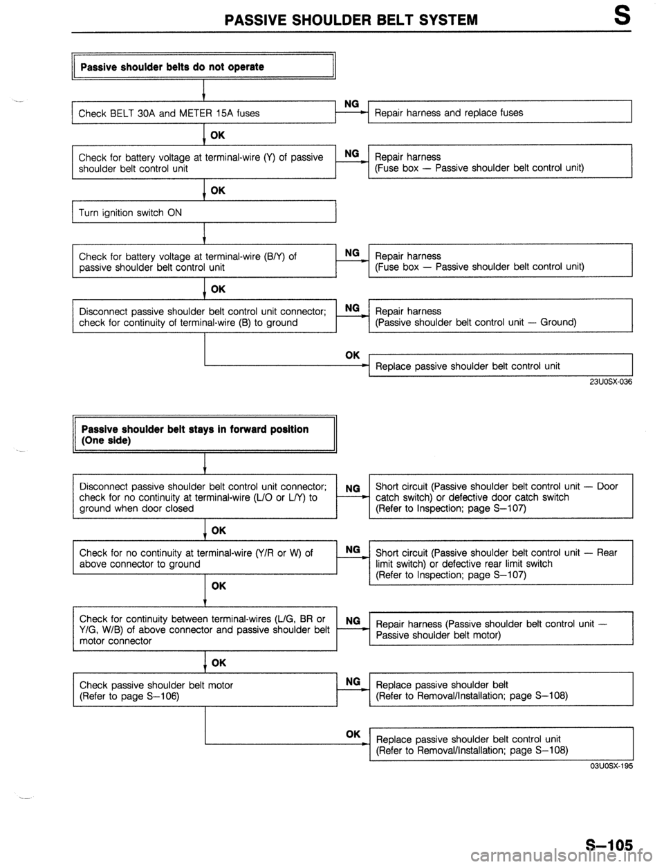
II Passive shoulder belts do not operate
II
. .
Repair harness and replace fuses OK
Check for battery voltage at terminal-wire (Y) of passive E Repair harness
shoulder belt control unit (Fuse box - Passive shoulder belt control unit)
I
Turn ignition switch ON
Check for battery voltage at terminal-wire (B/Y) of
passive shoulder belt control unit OK
NG
Repair harness _
- (Fuse box - Passive shoulder belt control unit)
Disconnect passive shoulder belt control unit connector; NGz Repair harness
check for continuity of terminal-wire (B) to ground (Passive shoulder belt control unit - Ground)
Replace passive shoulder belt control unit
, 23UOSX-036 Passive shoulder belt stays in forward position
(One side)
I
Disconnect passive shoulder belt control unit connector; NG Short circuit (Passive shoulder belt control unit - Door
check for no continuity at terminal-wire (L/O or L/Y) to - - catch switch) or defective door catch switch
ground when door closed (Refer to Inspection; page S-107) OK
Check for no continuity at terminal-wire (Y/R or W) of
above connector to ground OK E Short circuit (Passive shoulder belt control unit - Rear
limit switch) or defective rear limit switch
(Refer to Inspection; page S-107)
Check for continuity between terminal-wires (L/G, BR or NG
Y/G, W/B) of above connector and passive shoulder belt Repair harness (Passive shoulder belt control unit -
motor connector Passive shoulder belt motor)
I
1 OK
Check passive shoulder belt motor
(Refer to page S-106) Replace passive shoulder belt NO
:
(Refer to Removal/Installation; page S-l 08) OK
_ Replace passive shoulder belt control unit
I (Refer to Removal/Installation; page S-l 08) L I
03uosx-195
S-l 05