light MAZDA PROTEGE 1992 Owner's Manual
[x] Cancel search | Manufacturer: MAZDA, Model Year: 1992, Model line: PROTEGE, Model: MAZDA PROTEGE 1992Pages: 1164, PDF Size: 81.9 MB
Page 156 of 1164

ON-VEHICLE MAINTENANCE
OWOBX-05.
OxJOBX-05,
ENOBX-056
--
Caution
l Do not allow any sealant on the camshaft journal
surfaces.
.-
3. Apply silicone sealant to the shaded areas shown in the
figure.
4. Install the camshaft caps according to the cap number and
arrow mark.
5. install the camshaft cap bolts and tighten them in two or
three steps in the order shown in the figure.
Tightening torque:
11.3-l 4.2 N-m (1 .15--l .45 m-kg, loo-126 in-lb)
6. Apply a small amount of clean engine oil to the lip of a new
camshaft oil seal.
7. Push the oil seal slightly in by hand.
Caution
l The oil seal must be tapped in until it is flush with
the edge of the camshaft cap.
8. Tap the oil seal in evenly with a suitable pipe and a hammer.
Oil seal outer diameter: 46mm (1.69 in)
Camshaft pulley
1. Turn the camshafts until the camshaft dowel pins face
straight up.
2. Install the camshaft pulleys with the I mark (intake side) or
the E mark (exhaust side) straight up.
I II’- ,
J
05UOBX-057
B2-24
Page 159 of 1164

ON-VEHICLE MAINTENANCE
I 05UOBX-063
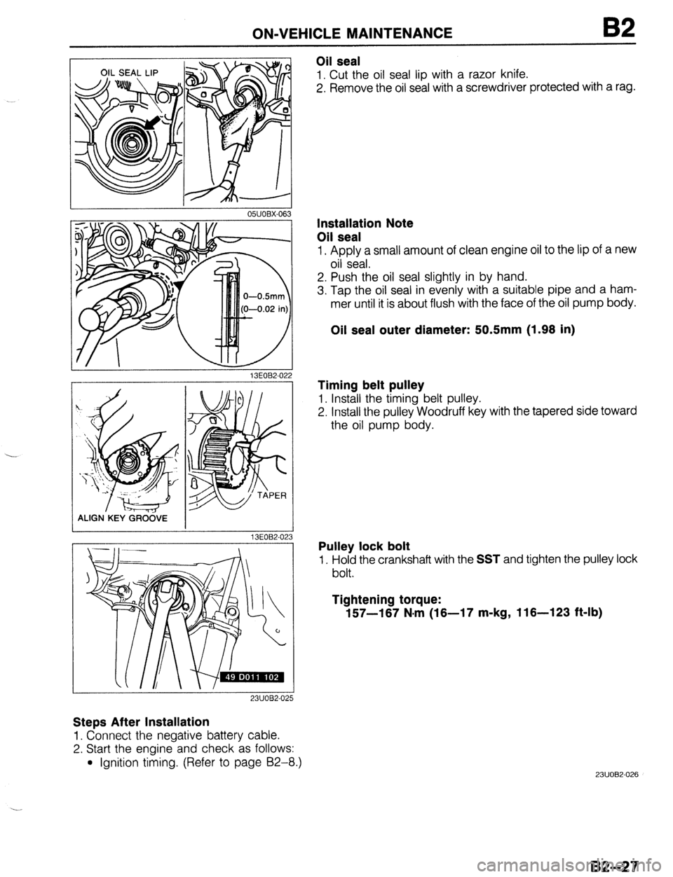
Oil seal
1. Cut the oil seal lip with a razor knife.
2. Remove the oil seal with a screwdriver protected with a rag.
13EOB2-02
ALIGN.KEY GRCi&E
13EOB2-02
23UOB2-025
Steps After Installation
1. Connect the negative battery cable.
2. Start the engine and check as follows:
l Ignition timing. (Refer to page 92-8.)
3
Installation Note
Oil seal
1. Apply a small amount of clean engine oil to the lip of a new
oil seal.
2. Push the oil seal slightly in by hand.
3. Tap the oil seal in evenly with a suitable pipe and a ham-
mer until it is about flush with the face of the oil pump body.
Oil seal outer diameter: 50.5mm (1.98 in)
Timing belt pulley
1. Install the timing belt pulley.
2. Install the pulley Woodruff key with the tapered side toward
the oil pump body.
Pulley lock bolt
1. Hold the crankshaft with the SST and tighten the pulley lock
bolt.
Tightening torque:
157-187 N.m (18-17 m-kg, 116-123 ft-lb)
23UOB2-026
82-27
Page 161 of 1164

ON-VEHICLE MAINTENANCE
Drive plate (ATX)
1. Hold the drive plate with the SST or equivalent.
2. Remove the drive plate lock bolts.
3. Remove the backing plate, drive plate, and adapter.
2311082-052
I
Oil seal
1. Cut the oil seal lip with a razor knife.
2. Remove the oil seal with a screwdriver protected with a rag.
I I
I
05UOBX-063
Installation note
Oil seal
1, Apply a small amount of clean engine oil to the lip of a new
oil seal.
2. Push the oil seal slightly in by hand.
OWOBX-069
APPLY SEALANT
03UOB2.04
Caution
l The oil seal must be tapped in untjl it is flush with
the edge of the rear cover.
3. Tap the oil seal in evenly with a suitable pipe and a hammer.
Oil seal outer diameter: 1OOmm (3.94 in)
Flywheel (MTX)
1. Remove the sealant from the flywheel bolt holes in the crank-
shaft and from the flywheel bolts.
Caution
l If all the previous sealant cannot be removed from
a bolt, replace the bolt.
l Do not apply sealant if a new bolt is used.
2. Set the flywheel onto the crankshaft.
3. Apply sealant to the flywheel bolts and install them.
4. Hold the flywheel with the
SST or equivalent.
5. Tighten the bolts in two or three steps in the order shown
in the figure.
Tightening torque:
1 96-103 N-m (9.6-10.5 m-kg, 71-76 ft-lb)
2311082-053
B2--29
Page 188 of 1164

82 INSPECTION / REPAIR
03UOB2-082
13UOB2-0.
1
9MUOB2-112
I
03UOB2-08:
8. Measure the height @of each valve guide. Replace the
valve guide if necessary.
Height: 18.3-l 8.9mm (0.720-0.744 in)
Replacement of valve guide
Note
l The valve guides are different between intake and
exhaust sides, use the correct valve guide.
Removal
1. Remove the valve guide from the side opposite the com-
bustion chamber with the
SST.
Installation
1. Assemble the SST so that depth L is as specified.
Depth L: 18.3-18.9mm (0.720-0.744 in)
2. lighten the locknut.
3. Tap the valve guide in from the side opposite the combus-
tion chamber until the
SST contacts the cylinder head.
4. Verify that the valve guide height is within specification.
5. If not within specification, repeat Steps 1-4.
82-56
Page 206 of 1164

B2 ASSEMBLY
x9 05UOBX-20
OWOBX-203
Rear Cover
1, Apply a small amount of clean engine oil to the lip of a new
oil seal.
2. Push the oil seal slightly in by hand. -,
Caution
l The oil seal must be pressed in until it is flush with
the edge of the rear cover.
3. Press the oil seal in evenly with a suitable pipe.
Oil seal outer diameter: 1OOmm (3.94 in)
4. Apply silicone sealant to the shaded area shown in the
figure.
5. Install the rear cover.
Tightening torque:
7.8-l 1 N*m (80-l 10 cm-kg, 69-95 in-lb)
Oil Pump
1. Apply a small amount of clean engine oil to the lip of a new
oil seal.
2. Push the oil seal slightly in by hand.
Caution
l The oil seal must be pressed in until it is flush with
the edge of the oil pump body.
3. Press the oil seal in evenly with a suitable pipe.
Oil seal outer diameter: 44mm (1.73 in)
4. Install the oil pump and a new gasket.
Tightening torque:
19-25 N#m (1.9-2.6 m-kg, 14-19 ft-lb)
Page 212 of 1164

62 ASSEMBLY
I OWOBX-21!
I CYLINDER HEAD SIDE
05UOBX-2
I
05UOBX-21 6
i
17
05UOBX-2
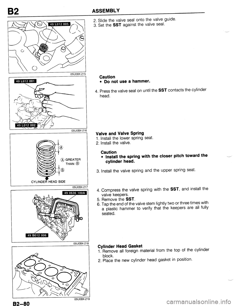
2. Slide the valve seal onto the valve guide.
3. Set the
SST against the valve seal.
Caution
l Do not use a hammer.
4. Press the valve seal on until the SST contacts the cylinder
head.
Valve and Valve Spring
1. Install the lower spring seat.
2. Install the valve.
Caution
l Install the spring with the closer pitch toward the
cylinder head. .---
3. Install the valve spring and the upper spring seat.
4. Compress the valve spring with the
SST, and install the
valve keepers.
5. Remove the
SST.
6. Tap the end of the valve stem lightly two or three times with
a plastic hammer to verify that the keepers are all fully
seated.
Cylinder Head Gasket
1. Remove all foreign material from the top of the cylinder
block.
2. Place the new cylinder head gasket in position.
82-80
Page 214 of 1164

B2 ASSEMBLY
DlSTRlBUfOR
DRIVE GROOVE
-- 03umx-01
-
05UOBX-05
--____--
udOBX-056
---I
Camshaft
Note
l The exhaust camshaft is grooved for the distribu-
tor drive.
1. Apply clean engine oil to the camshaft journals and bearings.
2. Install the camshaft in position.
Caution
l Do not allow any sealant on the camshaft journal
surfaces.
3. Apply silicone sealant to the shaded areas shown in the
figure.
4. Install the camshaft caps according to the cap number and
arrow mark.
5. Install the camshaft cap bolts and tighten them in two or
three steps in the order shown in the figure.
Tightening torque:
11.3-14.2 Nlm (1.15-l .45 m-kg, loo-126 in-lb)
6. Apply a small amount of clean engine oil to the lip of a new
camshaft oil seal.
7. Push the oil seal slightly in by hand.
Caution
l The oil seal must be tapped in until it is flush with
the edge of the camshaft cap.
8. Tap the oil seal in evenly with a suitable pipe and a hammer.
Oil seal outer diameter: 48mm (1.89 in)
Seal Plate
1. Install the seal plate on the cylinder head.
Tightening torque:
7.8-l 1 N-m (80-l 10 cm-kg, 69-95 in-lb)
~,. ,
03”oEm10:
B2-82
Page 231 of 1164

INSTALLATION
Step 4
I. Connect the hoses shown in the figure.
Caution Speedometer cable
1. Install the speedometer cable.
Exhaust pipe
1. Install the exhaust pipe and a gasket; then loosely tighten
the lock nuts.
2. Loosely tighten the bracket bolts.
3. Tighten the lock nuts.
Tightening torque:
31-46 N-m (3.2-4.7 m-kg, 23-34 ft-lb)
4. Tighten the bracket bolts.
Tightening torque:
37-52 N.m (3.8-5.3 m-kg, 27-38 ft-lb)
l Position the hose clamp in the original location on the hose, and squeeze the clamp lightly
with large pliers to ensure a good fit.
VACUUM HOSE
(CRUISE CONTROL) BRAKE, VACUUM HOSE 1 VACUUM HOSE
(PURGE CONTROL)
HEATER HOSE
FUE’L HOSE
03UOB2-14
B2-9:
Page 233 of 1164

INSTALLATION
03UOB2-141
/ 03UOB2-14!
1 03UOB2-150
03UOB2-151
8,’
1
a : :“.;,
.’
s,::, ; i .:.;...
..:.a.. :..,:.
. .
. .
” . : 0 ,.: ::
: .:.. ..,
., ‘:;
.<.,:.,);
‘zi :
I 0311082-152
A/C compressor (If equipped)
1. Install the A/C compressor.
Tightening torque:
24-35 N,m (2.4-3.6 m-kg, 17-26 ft-lb)
2. Tighten the A/C pipe bracket to the engine mount member.
Tightening torque:
6.4-9.3 N-m (65-95 cm-kg, 56-62 in-lb)
P/S oil pump and bracket
1. Install the P/S oil pump and bracket.
Tightening torque:
37-52 N.m (3.8-5.3 m-kg, 27-38 ft-lb)
Drive belt
1. Install the P/S and/or A/C drive belt.
2. Adjust the drive belt deflections. (Refer to page B2-6.)
Radiator and cooling fan assembly
1. Install the radiator and cooling fan assembly.
Tightening torque:
7.8-11 N-m (80-110 cm-kg, 69-95 in-lb)
2. Connect the upper and lower radiator hoses.
Caution
l Position the hose clamp in the original location on
the hose, and squeeze the clamp lightly with large
pliers to ensure a good
fit.
3. Connect the coolant reservoir hose.
4. Connect the cooling fan connector.
5. Connect the oil cooler hose. (ATX)
B2-101
Page 248 of 1164

OIL PUMP
OWODX-032
r----‘---I ----
L-
---- 05UODX-033
r- __I_.__^--
_- .-.. --.-.__-----^---
---7--l
L-.-.LlLd-..- ..-.---A OWODX-034
___ll_--_l___-----------
___I- 1
.i
5
INSPECTION
Pressure Spring
1 Inspect the spring for weakness or breakage.
2. Measure the free length. Replace the spring if necessary.
Free length: 45.5mm (1.791 in) -
Rotor Clearance
1. Measure the following clearances. Replace the rotor if
necessary.
Tooth tip clearance: 0.20mm (0.0079 in) max.
Outer rotor to pump body clearance:
0.22mm (0.0087 in) max.
Side clearance: 0.14mm (0.0055 in) max.
Assembly Note
Oil seal
1, Apply a small amount of clean engine oil to the lip of a new
oil seal.
2. Push the oil seal slightly in by hand,
Caution
l The oil seal must be pressed in until it is flush with
the edge of the oil pump body.
-’
3. Press the oil seal in evenly with a suitable pipe.
Oil seal outer diameter: 44mm (1.73 in)