radiator MAZDA PROTEGE 1992 Owner's Guide
[x] Cancel search | Manufacturer: MAZDA, Model Year: 1992, Model line: PROTEGE, Model: MAZDA PROTEGE 1992Pages: 1164, PDF Size: 81.9 MB
Page 713 of 1164

WHEEL ALIGNMENT
WHEEL ALIGNMENT
PRE-INSPECTION
1. Check the tire inflations and set to the recommended pressure, if necessary.
2. Inspect the front wheel bearing play; replace the bearing if necessary.
3. inspect the wheel and tire runout.
4. Inspect the ball joints and steering linkage for any excessive looseness.
5. The vehicle must be on level ground and have no luggage or passenger load.
6. The difference in height between the left and right sides from the center of the wheel to the fender brim
must not exceed
10mm (0.39 in).
7. Shake the vehicle to check operation of the shock absorbers.
03UORX.007
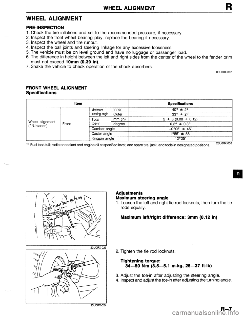
FRONT WHEEL ALIGNMENT
Specifications
item
Specifications
Maximum Inner 4o” f: 2O
steering angle Outer
33O f 2O
Total mm (in) 2 f 3 (0.08 f 0.12)
toe-in dearee 0.20 f 0.30 Wheel alignment
(*‘Unladen) Front
*I Fuel tank full; radiator coolant and Camber angle -0005 * 45’
Caster angle 1°55’ f 55’
Kingpin angle 12O25’
engine oil at specified level; and spare tire, jack, and tools in designated positions.
23UORX-008
I
I 23UORX-023
Adjustments
Maximum steering angle
1. Loosen the left and right tie rod locknuts, then turn the tie
rods equally.
Maximum left/right difference: 3mm (0.12 in)
2. Tighten the tie rod locknuts.
Tightening torque:
34-50 N-m (3.5-5.1 m-kg, 25-37 ft-lb)
3. Adjust the toe-in after adjusting the steering angle.
4. Inspect and adjust the toe-in after adjusting the turning angle.
I 23UORX-024
R-7
Page 715 of 1164

WHEEL ALIGNMENT
REAR WHEEL ALIGNMENT
Specifications
kern Specifications
Total mm (in) 2 f 3 (0.08 f 0.12)
Wheel alignment
(*‘Unladen) Rear toe-in
degree 0.2O f 0.3O
Camber angle -0020’ f 45’
*I Fuel tank full; radiator coolant and engine oil at specified level; and spare tire, jack, and tools in designated positions.
13UORX-012
Adjustment
Total toe-in
1. Loosen the lateral link locknuts.
2. Turn the lateral link adjustment link to adjust.
Note
l One turn of the link changes 11.3mm (0.44 in).
3. Tighten the lateral link locknuts to the specified torque.
Tightening torque:
55-64 N,m (5.6-6.5 m-kg, 41-47 ft-lb)
R-9
Page 737 of 1164

S
BODY
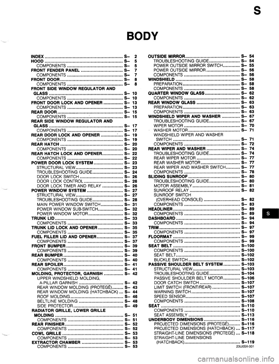
INDEX ........................................................ 2
HOOD ........................................................
COMPONENTS ........................................ t
FRONT FENDER PANEL .............................. ;I
COMPONENTS ........................................ S- ::
FRONT DOOR ............................................. S- 8
COMPONENTS ........................................ S- 8
FRONT SIDE WINDOW REGULATOR AND
GLASS ..................................................... s- 10
COMPONENTS ........................................ s- 10
FRONT DOOR LOCK AND OPENER .............. S- 13
COMPONENTS ........................................ s- 13
REAR DOOR ............................................... s- 15
COMPONENTS ........................................ s- 15
REAR SIDE WINDOW REGULATOR AND
GLASS ..................................................... s- 17
COMPONENTS ........................................ s- 17
REAR DOOR LOCK AND OPENER ...........
.-. ...
S- 19
COMPONENTS ........................................ s- 19
REAR HATCH ............................................. s- 20
COMPONENTS ........................................ s- 20
REAR HATCH LOCK AND OPENER.. .............
S- 22
COMPONENTS ........................................ s- 22
POWER DOOR LOCK SYSTEM.. ................... S- 23
STRUCTURAL VIEW .................................. S- 23
TROUBLESHOOTING GUIDE ...................... S- 24
DOOR LOCK SWITCH ............................... S- 28
DOOR LOCK CONTROL ............................ S- 26
DOOR LOCK TIMER AND RELAY ............... S- 26
POWER WINDOW SYSTEM .......................... S- 27
STRUCTURAL VIEW .................................. S- 27
TROUBLESHOOTING GUIDE.. .................... S- 28
MAIN POWER WINDOW SWITCH.. .............. S- 31
POWER WINDOW SUB-SWITCH.. ................ S- 32
POWER WINDOW MOTOR ......................... S- 32
TRUNK LID .................................................
s- 33
COMPONENTS ........................................ s- 33
TRUNK LID LOCK AND OPENER.. ................ S- 35
COMPONENTS ........................................ s- 35
FUEL FILLER LID AND OPENER ................... S- 37
COMPONENTS ........................................ s- 37
FRONT BUMPER ......................................... s- 39
COMPONENTS ........................................ s- 39
REAR BUMPER ........................................... s- 40
COMPONENTS ........................................ s- 40
REAR SPOILER ........................................... s- 41
COMPONENTS ........................................ s- 41
MOLDING, PROTECTOR, GARNISH .............. S- 42
UPPER WINDSHIELD MOLDING,
A-PILLAR GARNISH ................................ S- 42
REAR WINDOW MOLDING (PROTEGE) ........ S- 43
REAR WINDOW MOLDING (HATCHBACK) ... S- 44
ROOF MOLDING ...................................... S- 46
BELTLINE MOLDING ................................ S- 48
SIDE PROTECTOR.. .................................. S- 49
RADIATOR GRILLE, LOWER GRILLE
MOLDING ................................................. s- 51
COMPONENTS ........................................ S- 51
REAR FINISHER.. ........................................
S- 52
COMPONENTS ........................................ S- 52
COWL GRILLE ............................................ s- 53
COMPONENTS ........................................ s- 53
EXTRACTOR CHAMBER ..............................
COMPONENTS ........................................ g-
- ;; OUTSIDE MIRROR ....................................... s- 54
TROUBLESHOOTING GUIDE.. .................... S- 54
POWER OUTSIDE MIRROR SWITCH ............ S- 55
POWER OUTSIDE MIRROR.. ...................... S- 56
COMPONENTS ........................................ s- 66
WINDSHIELD .............................................. S- 58
PREPARATION ......................................... S- 58
COMPONENTS ........................................ S- 58
QUARTER WINDOW GLASS ......................... S- 62
COMPONENTS .................. ..T ................... S- 82
REAR WINDOW GLASS ............................... S- 63
PREPARATION ......................................... S- 63
COMPONENTS ........................................ S- 63
WINDSHIELD WIPER AND WASHER ............. S- 87
TROUBLESHOOTING GUIDE.. .................... S- 67
WIPER MOTOR ........................................ s- 70
WASHER MOTOR ..................................... s- 71
WINDSHIELD WIPER AND WASHER
SWITCH ................................................ s- 71
COMPONENTS ........................................ S- 72
REAR WIPER AND WASHER ........................ S- 74
TROUBLESHOOTING GUIDE.. .................... S- 74
REAR WIPER MOTOR ............................... s- 77
REAR WASHER MOTOR ............................ s- 77
REAR WIPER AND WASHER SWITCH.. ........ S- 77
COMPONENTS ........................................ S- 78
SLIDING SUNROOF ..................................... S- 80
TROUBLESHOOTING GUIDE.. .................... S- 80
MOTOR ASSEMBLY .................................. S- 81
SUNROOF RELAY .................................... S- 82
SUNROOF SWITCH
(OVERHEAD CONSOLE) .......................... S- 82
COMPONENTS ........................................ S- 83
HEADLINER ................................................ S- 89
COMPONENTS ........................................ S- 89
DASHBOARD .............................................. s- 94
COMPONENTS ........................................ s- 94
TRIM .......................................................... s- 97
COMPONENTS ........................................ s- 97
FLOORMAT ................................................ s- 99
COMPONENTS ........................................ s- 99
SEAT BELT ................................................ S-l 00
COMPONENTS ........................................ S-l 00
SEAT BELT .............................................. S-l 02
BUCKLE SWITCH ..................................... s-102
PASSIVE SHOULDER BELT SYSTEM.. .......... S-103
STRUCTURAL VIEW .................................. s-103
TROUBLESHOOTING GUIDE.. .................... S-104
PASSIVE SHOULDER BELT MOTOR.. .......... S-106
DOOR CATCH SWITCH ............................. S-l 07
LIMIT SWITCH (FRONT/REAR)
WARNING SWITCH ....................................................... z-:X;
-
SPEED SENSOR ....................................... s-i 07
COMPONENTS ........................................ S-l 08
SEAT ......................................................... s-110
COMPONENTS ........................................ s-110
SEAT ASSEMBLY ..................................... S-l 13
UNDERBODY DIMENSIONS .............. ..: ......... S-116
PROJECTED DIMENSIONS (PROTEGE) ........ S-116
PROJECTED DIMENSIONS (HATCHBACK). .. S-117
STRAIGHT-LINE DIMENSIONS (PROTEGE). .. S-118
STRAIGHT-LINE DIMENSIONS
(HATCHBACK) ........................................ s-119
23UOSX.001
Page 738 of 1164

INDEX
NDEX
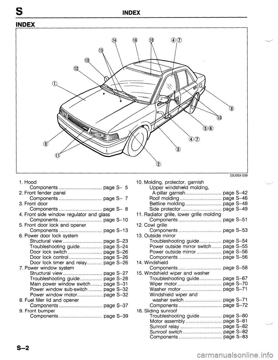
1. Hood
Components ............................... page S- 5
2. Front fender panel
Components ............................... page S- 7
3. Front door
Components ............................... page S- 8
4. Front side window regulator and glass
Components ............................... page S-l 0
5. Front door lock and opener
Components ............................... page S-l 3
6. Power door lock system
Structural view.. .......................... page S-23
Troubleshooting guide.. .............. page S-24
Door lock switch.. ....................... page S-26
Door lock control.. ...................... page S-26
Door lock timer and relay ........... page S-26
7. Power window system
Structural view ............................ page S-27
Troubleshooting guide.. .............. page S-28
Main power window switch.. ...... page S-31
Power window sub-switch .......... page S-32
Power window motor .................. page S-32
8. Fuel filler lid and opener
Components ............................... page S-37
9. Front bumper
Components ............................... page S-39
23UOSX-03
10. Molding, protector, garnish
Upper windshield molding,
A-pillar garnish.. ........................ page S-42
Roof molding .............................. page S-46
Beltline molding.. ........................ page S-48
Side protector.. ...........................
page S-49
11. Radiator grille, lower grille molding
Components ....................... . ....... page S-51
12. Cowl grille
Components ............................... page S-53
13. Outside mirror
Troubleshooting guide ................ page S-54
Power outside mirror switch.. ..... page S-55
Power outside mirror.. ................ page S-56
Components ............................... page S-56
14. Windshield
Components ...............................
page S-58
15. Windshield wiper and washer
Troubleshooting guide.. .............. page S-67
Wiper motor ................................ page S-70
Washer motor.. ........................... page S-71
Windshield wiper and
washer switch ........................... page S-71
Components ............................... page S-72
16. Sliding sunroof
Troubleshooting guide ................ page S-80
Motor assembly.. ........................ page S-81
Sunroof relay ..............................
page S-82 .--‘-
Sunroof switch ............................ page S-82
Components ............................... page S-83
s-2
Page 741 of 1164

HOOD
. COMPONENTS
Removal / Installation
1. Remove in the order shown in the figure.
2. Install in the reverse order of removal.
Note
l Remove the radiator grille for removal of the hood lock. (Refer to page S-51.)
19-25
(1.9-2.6, 19-25 11.9-2.6s
[80-110 cm-kg, 69-96 in-lb) 7.8-11 N.m L mfj
N.m (m-kg, ft-lb
p ,mx.nnE.
1. Washer pipe 6. Weatherstrip
2. Hood hinge 7. Hood stay
3. Hood 8. Hood lock
Adjustment Note . . . . . . . . . . . . . . . . . . . . . . . . . . . page S-6 Adjustment Note ..,.,...................... page S-6
4. Hood insulator 9. Release wire
5. Hood deflector
S-5
Page 743 of 1164

FRONT FENDER PANEL S
FRONT FENDER PANEL
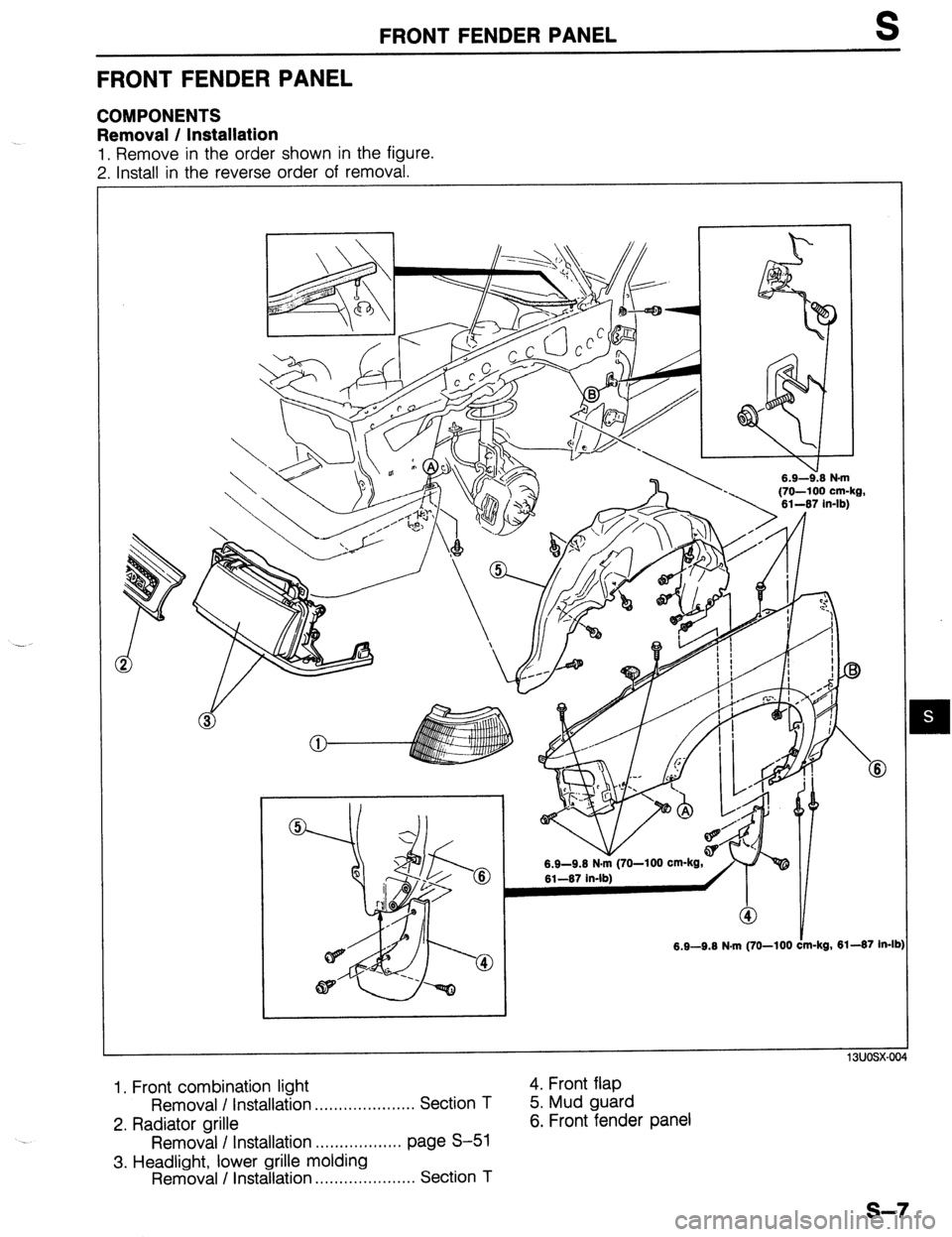
COMPONENTS
Removal / Installation
1, Remove in the order shown in the figure.
7 Install in the reverse order of removal.
-. . . .-.-*. . .
6.9-9.6 N.m (70-100
13uosx-004
1. Front combination light
Removal I Installation . . . . . . . . . . . . . . . . . . . . . Section T
2. Radiator grille
Removal I Installation .,................ page S-51
3. Headlight, lower grille molding
Removal / Installation .,,.,......,......... Section T 4. Front flap
5. Mud guard
6. Front fender panel
s-7
Page 775 of 1164

FRONT BUMPER S
FRONT BUMPER
COMPONENTS
Removal / Installation
1. Disconnect the negative battery cable.
2. Remove in the order shown in the figure.
3. Install in the reverse order of removal.
16-23 (1.6-2.3, 12-17
6.9-9.6 N.m (70-100 cc-kg,
61-67 in-lb) 16-23 (1.6-2.3, 12-17) /
6.9-9.6 N.m (70-100 cm-kg, 61-67 in-lb)
N.m (m-kg, Mb)
1. Front combination light
Removal / Installation . . . . . . . . . . . . . . . . . . . . . Section
T
2. Radiator grille
Removal I Installation . . . . . . . . . . . . . . . . . . page S-51
3. Headlight and lower grille molding
Removal / Installation . . . . . . . . . . . . . . . . . . . . . Section
T
4. Front bumper assembly
a. Front bumper reinforcement and bracket
b. Energy absorbing foam
c. Front bumper facia
5. License plate holder
6. Front bumper bracket
s-39
Page 787 of 1164

RADIATOR GRILLE, LOWER GRILLE MOLDING S
RADIATOR GRILLE, LOWER GRILLE MOLDING
COMPONENTS
Removal / Installation
1. Remove in the order shown in the figure.
2. Install in the reverse order of removal, referring to Installation Note.
1. Radiator grille 3. Lower grille molding
Installation Note. . . . . . . . . . . . . . . . . . . . .
page S-51 4. Clip
2. Front combination light
Removal I Installation ..,.,,...,..,........ Section T
Installation Note
Radiator grille
1. Insert the clips into the grille, and align them with the instal-
lation holes in the body.
2. Press the grille into the body.
s-51
Page 1008 of 1164

U AIR CONDITIONER
RECEIVER/DRIER
Removal / Installation
1. Discharge the refrigeration system. (Refer to page U-32.)
2. Remove the radiator grille. (Refer to Section S.)
3. Remove the receiver/drier as shown in the figure.
Note
l Immediately plug the open fittings to keep moisture out of the system.
4. Install the receiver/drier in the reverse order of removal.
Note
l Apply clean compressor oil to the O-rings before connecting the fittings.
l Do not apply compressor oil to the fitting nuts.
l When installing a new receiver/drier, add compressor oil through the high-pressure pipe port
of the compressor.
Compressor oil: 10 cc (0.61 cu in)
Tightening torque
Receiver/drier inlet: 9.8-20 N*m (1.0-2.0 m-kg, 7.2-14 ft-lb)
Receiver/drier outlet: 15-25 N-m (1.6-2.6 m-kg, 11-18 ft-lb)
1. Receiver/drier .-
u-52
Page 1009 of 1164

AIR CONDITIONER U
CONDENSER
Removal / Installation
1. Discharge the refrigeration system. (Refer to page U-32.)
2. Remove the radiator grille. (Refer to Section S.)
3. Remove the receiver/drier. (Refer to page U-52.)
4. Remove the condenser as shown in the figure.
Note
l Insert a protector such as cardboard between the condenser and the radiator.
l Immediately plug the open fittings to keep moisture out of the system.
5. install the condenser in the reverse order of removal.
Note
l Apply clean compressor oil to the O-rings before connecting the fittings.
l Do not apply compressor oil to the fitting nuts.
l Remove the protector before installing the radiator brackets.
l When installing a new condenser, add compressor oil through the high-pressure pipe port
of the compressor.
Compressor oil: 30 cc (1.83 cu in)
Tightening torque
Condenser inlet: 15-25 N*rn (1.5-2.5 m-kg, 11-18 ft-lb)
Condenser outlet: 9.8-20 N#m (1 .O-2.0 m-kg, 7.2-14 ft-lb)
1. Radiator bracket
2. Radiator 3. Condenser
23UOUX-01
Inspection
Check for the following and repair or replace the condenser
as necessary.;
1. Cracks, damage, or refrigerant leakage.
2. Bent fins.
3. Distorted or damaged condenser inlet or outlet.
u-53