Open MERCEDES-BENZ B-Class 2017 W246 Manual Online
[x] Cancel search | Manufacturer: MERCEDES-BENZ, Model Year: 2017, Model line: B-Class, Model: MERCEDES-BENZ B-Class 2017 W246Pages: 290, PDF Size: 19.81 MB
Page 229 of 290
X
To program the remote control: point
garage door remote control 0083towards but-
tons 0044to0085 on the rear-view mirror at a dis-
tance of 2to 8 in (5 to 20 cm).
X Press and hold button 0084on remote control
0083 until indicator lamp 0043lights up green.
When indicator lamp 0043lights up green: pro-
gramming is finished.
When indicator lamp 0043flashes green: pro-
gramming was successful. The next step is to synchronize the rolling code (Y page 227).
X Release button 0084on remote control 0083for
the garage door drive system.
If indicator lamp 0043lights up red: repeat the
programing procedure for the corresponding
button on the rear-view mirror. When doing
so, vary the distance between remote control 0083 and the rear-view mirror.
The required distance between remote con-
trol 0083and the integrated garage door opener
depends on the garage door drive system.
Several attempts might be necessary. You
should test every position for at least
25 seconds before trying another position.
Synchronizing the rolling code
Pay attention to the "Important safety notes"
(Y page 226).
If the garage door system uses a rolling code,
you will also have to synchronize the garage
door system with the integrated garage door
opener in the rear-view mirror. To do this you will
need to use the programming button on the door
drive control panel. The programming button
may be located in different places depending on the manufacturer. It is usually located on the
door drive unit on the garage ceiling.
Familiarize yourself with the garage door drive
operating instructions, e.g. under "Program-
ming additional remote controls", before carry-
ing out the following steps.
Your vehicle must be within reach of the garage
door or gate opener drive. Make sure that nei-
ther your vehicle nor any persons/objects are
present within the sweep of the door or gate.
X Turn the SmartKey to position 2in the ignition
lock (Y page 109).
X Get out of the vehicle.
X Press the programming button on the door
drive unit.
Usually, you now have 30 second sto initiate
the next step. X
Get into the vehicle.
X Press previously programed button 0044,0087
or 0085 on the integrated garage door opener
repeatedly and in quick succession until the
door closes.
The rolling code synchronization is then com- plete.
Notes on programming the remote con-
trol
Canadian radio frequency laws require a "break"
(or interruption) of the transmission signals
after broadcasting for a few seconds. Therefore, these signals may not last long enough for the
integrated garage door opener. The signal is not
detected during programming. Comparable with Canadian law, some U.S. garage door openers
also feature a "break".
Proceed as follows:
R if you live in Canada
R if you have difficulties programming the
garage door opener (regardless of where you
live) as you follow the programming steps.
X Press and hold one of buttons 0044to0085 on the
integrated garage door opener.
After a short time, indicator lamp 0043lights up
yellow.
X Release the button.
Indicator lamp 0043flashes yellow.
X Press button 0084of garage door remote con-
trol 0083for two seconds, then release it for two
seconds.
X Press button 0084again for two seconds.
X Repeat this sequence on button 0084of remote
control 0083until indicator lamp 0043lights up
green.
When indicator lamp 0043lights up green: pro-
gramming is finished.
When indicator lamp 0043flashes green: pro-
gramming was successful. The next step is to
synchronize the rolling code.
X Release button 0084of remote control 0083of the
garage door drive.
If indicator lamp 0043lights up red: repeat the
programming process for the corresponding
button on the rear-view mirror. When doing
so, vary the distance between remote control 0083 and the rear-view mirror.
The required distance between remote con-
trol 0083and the integrated garage door opener
depends on the garage door drive system.
Several attempts might be necessary. You Features
227Stowage an d features Z
Page 230 of 290
should test every position for at least
25 seconds before trying another position.
Problems when programming If you are experiencing problems programming
the integrated garage door opener on the rear-
view mirror, take note of the following instruc-
tions:
R Check the transmitter frequency used by
garage door drive remote control 0083and
whether it is supported. The transmitter fre-
quency can usually be found on the back of
remote control 0083for the garage door drive.
The integrated garage door opener is com-
patible with devices that have units which
operate in the frequency range of 280 to
433 MHz.
R Replace the batteries in garage door remote
control 0083. This increases the likelihood that
garage door remote control 0083will transmit a
strong and precise signal to the integrated
garage door opener.
R When programming, hold remote control 0083
at varying distances and angles from but-
tons 0044to0085 which you are programming. Try
various angles at a distance between 2and
8 inches (5to 20 cm) or at the same angle but at varying distances.
R If another remote control 0083is available for
the same garage door drive, repeat the same
programming steps with this remote control
0083. Before performing these steps, make sure
that new batteries have been installed in
garage door drive remote control 0083.
R Note that some remote controls only transmit
for a limited amount of time (the indicator
lamp on the remote control goes out). Press
button 0084on remote control 0083again before
transmission ends.
R Align the antenna cable of the garage door
opener unit. This can improve signal recep-
tion/transmission.
Opening/closing the garage door After it has been programmed, the integrated
garage door opener performs the function of the
garage door system remote control. Please also read the operating instructions for the garage
door system. X
Turn the SmartKey to position 2in the ignition
lock (Y page 109).
X Press button 0044,0087or0085 which you have
programmed to operate the garage door.
Garage door system with a fixed code: indi-
cator lamp 0043lights up green.
Garage door system with a rolling code: indi-
cator lamp 0043flashes green.
The transmitter will transmit a signal as long
as the button is pressed. The transmission is
halted after a maximum of ten seconds and
indicator lamp 0043lights up yellow.
X Press button 0044,0087or0085 again if necessary.
Clearing the memory Make sure that you clear the memory of the
integrated garage door opener before selling the vehicle.
X Turn the SmartKey to position 2in the ignition
lock (Y page 109).
X Press and hold buttons 0044and 0085.
The indicator lamp initially lights up yellow
and then green.
X Release buttons 0044and 0085.
The memory of the integrated garage door
opener in the rear-view mirror is cleared. Compass
Calling up the compass 0043
Rear-view mirror
0044 Compass display
0087 Opening
The compass displays in which compass direc-
tion the vehicle is currently traveling: N N,NE
NE, E
E,
SE
SE, S
S,SW
SW, W
Wor NW
NW. 228
FeaturesStowage and features
Page 231 of 290
To receive a correct compass display reading,
the magnetic field zone must be set and the
compass calibrated.
Setting the compass X
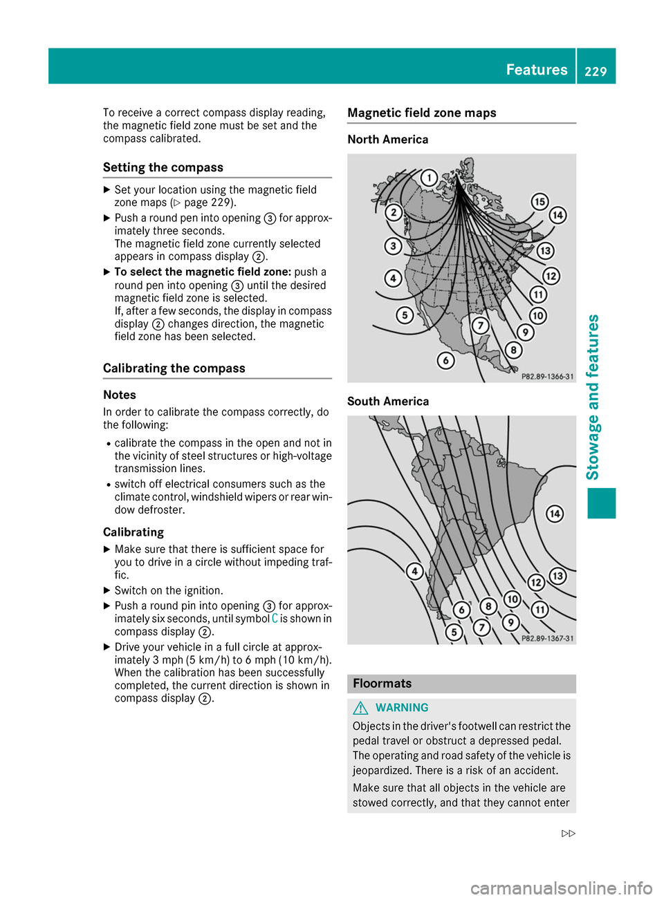
Set your location using the magnetic field
zone maps (Y page 229).
X Push a round pen into opening 0087for approx-
imately three seconds.
The magnetic field zone currently selected
appears in compass display 0044.
X To select the magnetic field zone: push a
round pen into opening 0087until the desired
magnetic field zone is selected.
If, after a few seconds, the display in compass
display 0044changes direction, the magnetic
field zone has been selected.
Calibrating the compass Notes
In order to calibrate the compass correctly, do
the following:
R calibrate the compass in the open and not in
the vicinity of steel structures or high-voltage
transmission lines.
R switch off electrical consumers such as the
climate control, windshield wipers or rear win-
dow defroster.
Calibrating
X Make sure that there is sufficient space for
you to drive in a circle without impeding traf-
fic.
X Switch on the ignition.
X Push a round pin into opening 0087for approx-
imately six seconds, until symbol C
C is shown in
compass display 0044.
X Drive your vehicle in a full circle at approx-
imately 3 mph (5 km/h) to 6 mph (10 km/h).
When the calibration has been successfully
completed, the current direction is shown in
compass display 0044. Magnetic field zone maps North America
South America
Floormats
G
WARNING
Objects in the driver's footwell can restrict the pedal travel or obstruct a depressed pedal.
The operating and road safety of the vehicle is
jeopardized. There is a risk of an accident.
Make sure that all objects in the vehicle are
stowed correctly, and that they cannot enter Features
229Stowage an d features
Z
Page 233 of 290
Engine compartment
Hood
Important safety notes G
WARNING
If the hood is unlatched, it may open up when the vehicle is in motion and block your view.
There is a risk of an accident.
Never unlatch the hood while driving. Before
every trip, ensure that the hood is locked. G
WARNING
When opening and closing the hood, it may
suddenly fall into the closed position. There is a risk of injury to persons within range of
movement of the hood.
Open and close the hood only when no one is
within its range of movement. G
WARNING
Certain components in the engine compart-
ment may be very hot, e.g. the drive system
and radiator. Working in the engine compart-
ment poses a risk of injury.
If possible, let the drive system cool down and only touch the components described in the
following. G
WARNING
The engine compartment contains moving
components. Certain components, such as
the radiator fan, may continue to run or start
again suddenly when the ignition is off. There is a risk of injury.
If you need to do any work inside the engine
compartment:
R switch off the ignition
R never reach into the area where there is a
risk of danger from moving components,
such as the fan rotation area
R remove jewelry and watches
R keep items of clothing and hair, for exam-
ple, away from moving parts Opening the hood G
WARNING
Certain components in the engine compart-
ment may be very hot, e.g. the drive system
and radiator. Working in the engine compart-
ment poses a risk of injury.
If possible, let the drive system cool down and only touch the components described in the
following. G
WARNING
When the hood is open and the windshield
wipers are set in motion, you can be injured by the wiper linkage. There is a risk of injury.
Always switch off the windshield wipers and
the ignition before opening the hood.
! Make sure that the windshield wipers are
not folded away from the windshield. You
could otherwise damage the windshield wip-
ers or the hood. X
Make sure that the windshield wipers are
switched off.
X Pull release lever 0043on the hood.
The hood is released. Engine compartment
231Maintenance and care Z
Page 234 of 290
X
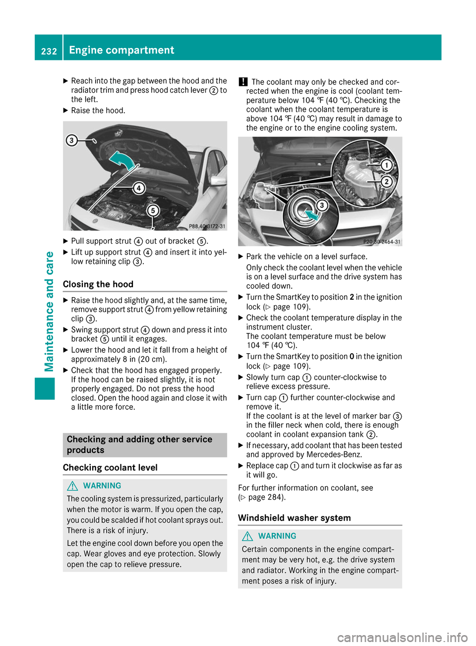
Reach into the gap between the hood and the
radiator trim and press hood catch lever 0044to
the left.
X Raise the hood. X
Pull support strut 0085out of bracket 0083.
X Lift up support strut 0085and insert it into yel-
low retaining clip 0087.
Closing the hood X
Raise the hood slightly and, at the same time,
remove support strut 0085from yellow retaining
clip 0087.
X Swing support strut 0085down and press it into
bracket 0083until it engages.
X Lower the hood and let it fall from a height of
approximately 8 in (20 cm).
X Check that the hood has engaged properly.
If the hood can be raised slightly, it is not
properly engaged. Do not press the hood
closed. Open the hood again and close it with a little more force. Checking and adding other service
products
Checking coolant level G
WARNING
The cooling system is pressurized, particularly when the motor is warm. If you open the cap, you could be scalded if hot coolant sprays out.
There is a risk of injury.
Let the engine cool down before you open the
cap. Wear gloves and eye protection. Slowly
open the cap to relieve pressure. !
The coolant may only be checked and cor-
rected when the engine is cool (coolant tem-
perature below 104 ‡ (40 †).Checking the
coolant when the coolant temperature is
above 104 ‡ (40 †) may result in damage to
the engine or to the engine cooling system. X
Park the vehicle on a level surface.
Only check the coolant level when the vehicle
is on a level surface and the drive system has
cooled down.
X Turn the SmartKey to position 2in the ignition
lock (Y page 109).
X Check the coolant temperature display in the
instrument cluster.
The coolant temperature must be below
104 ‡ (40 †).
X Turn the SmartKey to position 0in the ignition
lock (Y page 109).
X Slowly turn cap 0043counter-clockwise to
relieve excess pressure.
X Turn cap 0043further counter-clockwise and
remove it.
If the coolant is at the level of marker bar 0087
in the filler neck when cold, there is enough
coolant in coolant expansion tank 0044.
X If necessary, add coolant that has been tested
and approved by Mercedes-Benz.
X Replace cap 0043and turn it clockwise as far as
it will go.
For further information on coolant, see
(Y page 284).
Windshield washer system G
WARNING
Certain components in the engine compart-
ment may be very hot, e.g. the drive system
and radiator. Working in the engine compart-
ment poses a risk of injury. 232
Engine compartmentMaintenance and care
Page 235 of 290
If possible, let the drive system cool down and
only touch the components described in the
following. G
WARNING
Windshield washer concentrate is highly flam- mable. If it comes into contact with hot com-
ponents in the front compartment, it may
ignite. There is a risk of fire and injury.
Make sure that no windshield washer con-
centrate is spilled next to the filler neck. X
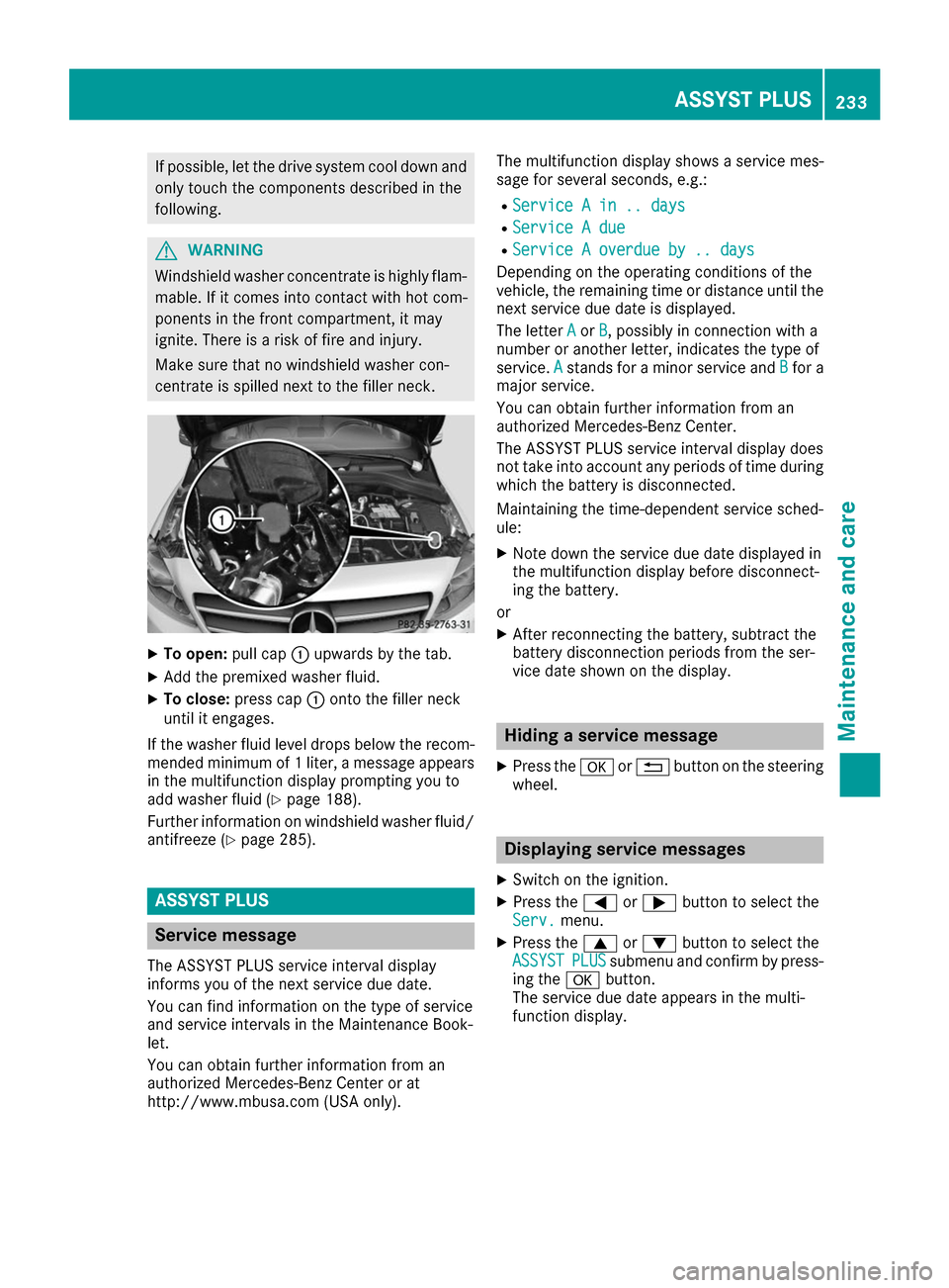
To open: pull cap0043upwards by the tab.
X Add the premixed washer fluid.
X To close: press cap 0043onto the filler neck
until it engages.
If the washer fluid level drops below the recom- mended minimum of 1 liter, a message appears
in the multifunction display prompting you to
add washer fluid (Y page 188).
Further information on windshield washer fluid/
antifreeze (Y page 285). ASSYST PLUS
Service message
The ASSYST PLUS service interval display
informs you of the next service due date.
You can find information on the type of service
and service intervals in the Maintenance Book-
let.
You can obtain further information from an
authorized Mercedes-Benz Center or at
http://www.mbusa.com (USA only). The multifunction display shows a service mes-
sage for several seconds, e.g.:
R Service A in .. days
Service A in .. days
R Service A due Service A due
R Service A overdue by .. days
Service A overdue by .. days
Depending on the operating conditions of the
vehicle, the remaining time or distance until the
next service due date is displayed.
The letter A Aor B
B, possibly in connection with a
number or another letter, indicates the type of
service. A Astands for a minor service and B
Bfor a
major service.
You can obtain further information from an
authorized Mercedes-Benz Center.
The ASSYST PLUS service interval display does
not take into account any periods of time during
which the battery is disconnected.
Maintaining the time-dependent service sched-
ule:
X Note down the service due date displayed in
the multifunction display before disconnect-
ing the battery.
or X After reconnecting the battery, subtract the
battery disconnection periods from the ser-
vice date shown on the display. Hiding a service message
X Press the 0076or0038 button on the steering
wheel. Displaying service messages
X Switch on the ignition.
X Press the 0059or0065 button to select the
Serv. Serv. menu.
X Press the 0063or0064 button to select the
ASSYST
ASSYST PLUS
PLUSsubmenu and confirm by press-
ing the 0076button.
The service due date appears in the multi-
function display. ASSYST PLUS
233Maintenance and care Z
Page 243 of 290
Where will I find...?
Vehicle tool kit
General notes Vehicles with a TIREFIT kit: the TIREFIT kit is
located in the stowage well under the cargo
compartment floor.
Vehicles with a tire-change tool kit: the tire-
change tool kit is in the stowage well under the
cargo compartment floor.
Apart from certain country-specific variations,
the vehicles are not equipped with a tire-change tool kit. Some tools for changing a wheel are
specific to the vehicle. For more information on
which tire changing tools are required and
approved to perform a wheel change on your
vehicle, consult a qualified specialist workshop.
Tools required for changing a wheel may
include, for example:
R Jack
R Wheel chock
R Lug wrench
R Alignment bolt
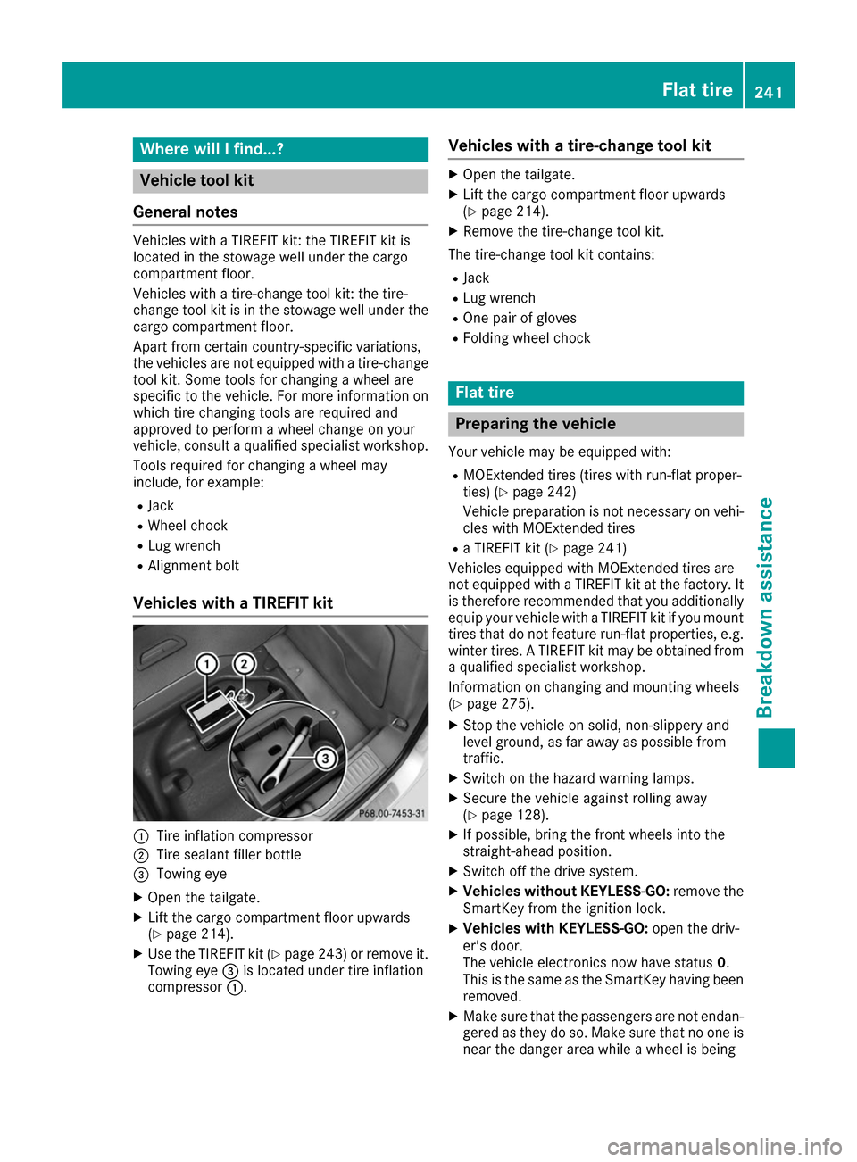
Vehicles with a TIREFIT kit 0043
Tire inflation compressor
0044 Tire sealant filler bottle
0087 Towing eye
X Open the tailgate.
X Lift the cargo compartment floor upwards
(Y page 214).
X Use the TIREFIT kit (Y page 243) or remove it.
Towing eye 0087is located under tire inflation
compressor 0043. Vehicles with a tire-change tool kit X
Open the tailgate.
X Lift the cargo compartment floor upwards
(Y page 214).
X Remove the tire-change tool kit.
The tire-change tool kit contains:
R Jack
R Lug wrench
R One pair of gloves
R Folding wheel chock Flat tire
Preparing the vehicle
Your vehicle may be equipped with:
R MOExtended tires (tires with run-flat proper-
ties) (Y page 242)
Vehicle preparation is not necessary on vehi-
cles with MOExtended tires
R a TIREFIT kit (Y page 241)
Vehicles equipped with MOExtended tires are
not equipped with a TIREFIT kit at the factory. It
is therefore recommended that you additionally
equip your vehicle with a TIREFIT kit if you mount tires that do not feature run-flat properties, e.g.
winter tires. A TIREFIT kit may be obtained from a qualified specialist workshop.
Information on changing and mounting wheels
(Y page 275).
X Stop the vehicle on solid, non-slippery and
level ground, as far away as possible from
traffic.
X Switch on the hazard warning lamps.
X Secure the vehicle against rolling away
(Y page 128).
X If possible, bring the front wheels into the
straight-ahead position.
X Switch off the drive system.
X Vehicles without KEYLESS-GO: remove the
SmartKey from the ignition lock.
X Vehicles with KEYLESS-GO: open the driv-
er's door.
The vehicle electronics now have status 0.
This is the same as the SmartKey having been removed.
X Make sure that the passengers are not endan-
gered as they do so. Make sure that no one is
near the danger area while a wheel is being Flat tire
241Breakdown assistance
Page 249 of 290
R
It is particularly important to observe the
described order when connecting and dis-
connecting the jumper cables.
R Never connect or disconnect the battery
terminals while the engine is running. G
WARNING
Battery acid is caustic. There is a risk of injury. Avoid contact with skin, eyes or clothing. Do
not inhale any battery gases. Do not lean over
the battery. Keep children away from batter-
ies. Wash away battery acid immediately with
plenty of clean water and seek medical atten- tion. H
Environmental note Batteries contain dangerous
substances. It is against the
law to dispose of them with
the household rubbish. They
must be collected separately
and recycled to protect the
environment. Dispose of batteries in an
environmentally friendly
manner. Take discharged
batteries to a qualified spe-
cialist workshop or a special
collection point for used bat-
teries.
! Have the battery checked regularly at a
qualified specialist workshop.
Observe the service intervals in the Mainte-
nance Booklet or contact a qualified specialist workshop for more information.
Comply with safety precautions and take pro-
tective measures when handling batteries. Risk of explosion.
Fire, open flames and smoking are
prohibited when handling the bat-
tery. Avoid creating sparks. Battery acid is caustic. Avoid contact
with skin, eyes or clothing.
Wear suitable protective clothing,
especially gloves, apron and face-
guard.
Rinse any acid spills immediately
with clear water. Contact a physician if necessary. Wear eye protection.
Keep children away.
Observe this Operator's Manual.
For safety reasons, Mercedes-Benz recom-
mends that you only use batteries which have
been tested and approved for your vehicle by
Mercedes-Benz. These batteries provide
increased impact protection to prevent vehicle
occupants from suffering acid burns should the battery be damaged in the event of an accident.
In order for the battery to achieve the maximum possible service life, it must always be suffi-
ciently charged.
Like other batteries, the vehicle battery may
discharge over time if you do not use the vehicle.In this case, have the battery disconnected at a
qualified specialist workshop. You can also
charge the battery with a charger recommended by Mercedes-Benz. Contact a qualified special-
ist workshop for further information.
Have the battery condition of charge checked
more frequently if you use the vehicle mainly for
short trips or if you leave it standing idle for a
lengthy period. Consult a qualified specialist
workshop if you wish to leave your vehicle
parked for a long period of time.
Only replace a battery with a battery that has
been recommended by Mercedes-Benz.
Remove the SmartKey if you park the vehicle
and do not require any electrical consumers.
The vehicle will then use very little energy, thus conserving battery power.
After an interruption to the power supply, such
as due to a discharged battery, you must reset
the clock via the multimedia system. You can Batteries
247Breakdown assistance Z
Page 250 of 290
find further information in the separate operat-
ing instructions. Charging the 12‑volt battery
G
WARNING
During charging and jump-starting, explosive
gases can escape from the battery. There is a risk of an explosion.
Particularly avoid fire, open flames, creating
sparks and smoking. Ensure there is sufficient
ventilation while charging and jump-starting.
Do not lean over a battery. G
WARNING
Battery acid is caustic. There is a risk of injury. Avoid contact with skin, eyes or clothing. Do
not inhale any battery gases. Do not lean over
the battery. Keep children away from batter-
ies. Wash away battery acid immediately with
plenty of clean water and seek medical atten- tion. G
WARNING
A discharged battery can freeze at tempera-
tures below freezing point. When jump-start-
ing the vehicle or charging the battery, gases can escape from the battery. There is a risk of
an explosion.
Allow the frozen battery to thaw out before
charging it or jump-starting.
! Only use battery chargers with a maximum
charging voltage of 14.8 V.
! Only
charge the battery using the jump-
starting connection point.
The jump-starting connection point is in the
engine compartment (Y page 249).
X Open the hood.
X Connect the battery charger to the positive
terminal and ground point in the same order
as when connecting the donor battery in the
jump-starting procedure (Y page 249).
If the indicator/warning lamps do not light up in
the instrument cluster at low temperatures, it is very likely that the discharged battery has fro-
zen. In this case you may neither jump-start the vehicle nor charge the battery. The service life of
a thawed-out battery may be shorter. The start-ing characteristics can be impaired, particularly at low temperatures. Have the thawed-out bat-
tery checked at a qualified specialist workshop.
Only charge the installed battery with a battery
charger which has been tested and approved byMercedes-Benz. A battery charger unit specially
adapted for Mercedes-Benz vehicles and tested
and approved by Mercedes-Benz is available as an accessory. It permits the charging of the bat-tery in its installed position. Contact an author-
ized Mercedes-Benz Center for further informa- tion and availability. Read the battery charger's
operating instructions before charging the bat-
tery. High-voltage battery – important
safety notes
G
DANGER
The vehicle's high-voltage electrical system is under high voltage. If you modify components
in the vehicle's high-voltage electrical system
or touch damaged components, you may be
electrocuted. The components in the vehi-
cle's high-voltage electrical system may be
damaged in an accident, although the damage is not visible. There is a risk of fatal injury.
Following an accident, do not touch any high- voltage components and never modify the
vehicle's high-voltage electrical system. Have
the vehicle towed away after an accident and
the vehicle's high-voltage electrical system
checked by a qualified specialist workshop. G
WARNING
In the event of a vehicle fire, the internal pres- sure of the high-voltage battery can exceed a
critical value. In this case flammable gas
escapes through a ventilation valve on the
underbody. The gas can ignite. There is a risk of injury.
Leave the danger zone immediately. Secure
the danger area at a suitable distance, whilst
observing legal requirements. 248
BatteriesBreakdown assistance
Page 251 of 290
The vehicle's high voltage electrical system is
under high voltage.
R Do not handle high-voltage components or
the orange cables of the vehicle's high-volt-
age electrical system.
R Do not touch high-voltage components or the
orange cables of the high-voltage electrical
system when a vehicle has been involved in a
crash.
R Do not touch any damaged components or
the damaged orange cables of the vehicle's
high-voltage electrical system.
R Do not remove the covers of the high-voltage
electrical system components that are
marked with a warning sticker.
Do not leave the vehicle parked for longer than
14 days with a high-voltage battery condition of
charge below 20%.
You can check the condition of charge in the
charge level display (Y page 153). If you park the vehicle and leave it stationary for
longer periods, connect it to a power supply.
If you leave the vehicle parked for longer than
four weeks, the battery may be damaged by
exhaustive discharging.
If you leave the vehicle parked for longer than six weeks, the vehicle may suffer damage as a
result of lack of use.
X Visit a qualified specialist workshop and seek
advice.
i You can obtain information about trickle
chargers from a qualified specialist work-
shop.
i Very low or very high outside temperatures
can impair the function of the high-voltage
battery (Y page 119). This can also occur
when the vehicle engine is switched off
(Y page 119). Jump-starting
For the jump-starting procedure, use only the jump-starting connection point, consisting of a pos- itive terminal and a ground point, in the engine compartment. G
WARNING
Battery acid is caustic. There is a risk of injury.
Avoid contact with skin, eyes or clothing. Do not inhale any battery gases. Do not lean over the
battery. Keep children away from batteries. Wash away battery acid immediately with plenty of
clean water and seek medical attention. G
WARNING
During charging and jump-starting, explosive gases can escape from the battery. There is a risk of an explosion.
Particularly avoid fire, open flames, creating sparks and smoking. Ensure there is sufficient ven-
tilation while charging and jump-starting. Do not lean over a battery. G
WARNING
During the charging process, a battery produces hydrogen gas. If a short circuit occurs or sparks
are created, the hydrogen gas can ignite. There is a risk of an explosion.
R Make sure that the positive terminal of a connected battery does not come into contact with
vehicle parts.
R Never place metal objects or tools on a battery.
R It is important that you observe the described order of the battery terminals when connecting
and disconnecting a battery.
R When jump-starting, make sure that the battery poles with identical polarity are connected. Jump-starting
249Breakdown assistance
Z