tow MERCEDES-BENZ C-CLASS SALOON 2007 Repair Manual
[x] Cancel search | Manufacturer: MERCEDES-BENZ, Model Year: 2007, Model line: C-CLASS SALOON, Model: MERCEDES-BENZ C-CLASS SALOON 2007Pages: 377, PDF Size: 6.19 MB
Page 226 of 377
Trailer towing*
22
3
R
has an increased braking distance
R is affected more by strong crosswinds
R demands more sensitive steering
R consumes more fue l
On long and steep downhill gradients you
must select a lower gear in good time, or on
vehicles with automatic transmission*, select
the shift range 1,2 or 3.
i This also applies if you have activated
cruise control* or Speedtronic*.
This uses the braking effect of the engine and
you will not have to brake to such an exten t
to maintain the same speed. This relieves the
load on the brake system and prevents the
brakes from overheating and wearing too
quickly. If you need additional braking ,
depress the brake pedal repeatedly rather
than continuously. G
Risk of accident
Never depress the brake pedal continu -
ously while the vehicle is in motion, e.g.
never cause the brakes to rub by applying
constant slight pedal pressure. This causes
the brake system to overheat, increases
the braking distance and can lead to the
brakes failing completely. Driving tips
R
Maintain a greater distance from the vehi-
cle in front than when driving without a
trailer.
R Avoid braking abruptly. If possible, brake
gently at first to allow the trailer to run on.
Then increase the braking force rapidly.
R The values given for gradient-climbing
capabilities from a standstill refer to sea
level. When driving in mountainous areas,
note that the power output of the engine
and with it its gradient-climbing capability
decrease with increasing altitude.
If the trailer swings from side to side:
X Do not accelerate.
X Do not counter-steer.
X Brake if necessary. G
Risk of accident
On no account should you attempt to dra w
the vehicle/trailer combination out by
increasing speed. Folding in the ball couplin
g
i Fold in the ball coupling when you are not
using the trailer tow hitch . G
Risk of injury
Make sure that no persons or animals are
in the pivoting range of the ball coupling.
Otherwise, they could be injured .
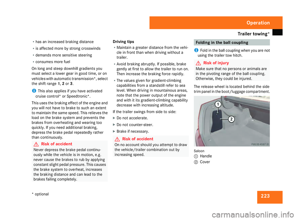
The release wheel is located behind the side
trim panel in the boot/luggage compartment. Saloon
1 Handl e
2 Cove r Operation
* optional
204_AKB; 2; 3, en-GB
mkalafa,
2007-06-26T23:11:51+02:00 - Seite 223
Page 227 of 377
Trailer towing*
22
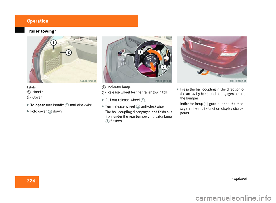
4 Estate
1
Handl e
2 Cove r
X To open: turn handle 1anti-clockwise.
X Fold cover 2down. 1
Indicator lamp
2 Release wheel for the trailer tow hitch
X Pull out release wheel 2.
X Turn release wheel 2anti-clockwise.
The ball coupling disengages and folds out
from under the rear bumper. Indicator lamp
1 flashes. X
Press the ball coupling in the direction of
the arrow by hand until it engages behind
the bumper.
Indicator lamp 1goes out and the mes-
sage in the multi-function display disap-
pears. Operation
* optional
204_AKB; 2; 3, en-GB
mkalafa,
2007-06-26T23:11:51+02:00 - Seite 224
Page 228 of 377
Trailer towing*
22
5 Trailer power suppl
y
When delivered from the factory, your vehi-
cle's trailer socket outlet is equipped with a
permanent power supply and a power supply
that is switched on via the ignition lock .
The permanent power supply is supplied via
trailer socket pin 9.
The power supply that is switched on via the
ignition lock is supplied via trailer socket pin
10.
! You can connect consumers with a power
rating of up to 240 W to the permanen t
power supply and up to 180 W to the power
supply that is switched on via the ignition
lock .
You must not charge a trailer battery using
the power supply.
You can obtain further information about
installing the trailer electrics from a qualified
specialist workshop, e.g. a Mercedes-Ben z
Service Centre.
X To switch the switched power supply on
or off: turn the key in the ignition lock to
position 2or 0, respectively. Trailer with 7-pin connector
If your trailer has a 7-pin connector, you can
connect it to the 13-pin socket on the ball
coupling using an adapter or, if necessary, an
adapter cable. Both of these can be obtained
at a qualified specialist workshop, e.g. at a
Mercedes-Benz Service Centre.
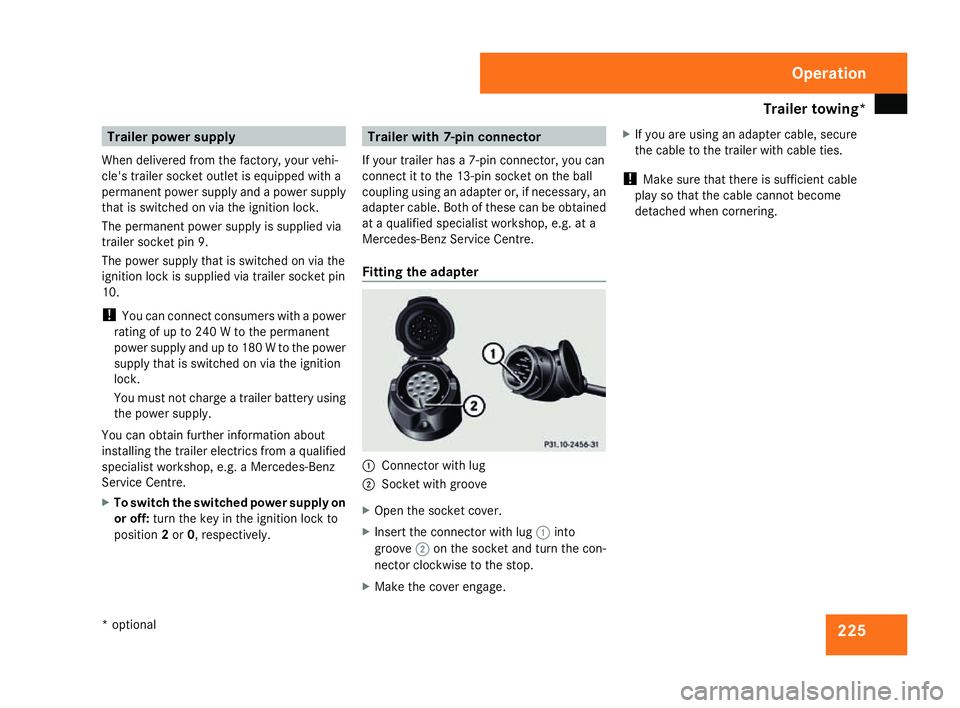
Fitting the adapter 1
Connector with lug
2 Socket with groove
X Open the socket cover.
X Insert the connector with lug 1into
groove 2on the socket and turn the con-
nector clockwise to the stop.
X Make the cover engage. X
If you are using an adapter cable, secure
the cable to the trailer with cable ties.
! Make sure that there is sufficient cable
play so that the cable cannot become
detached when cornering. Operation
* optional
204_AKB; 2; 3, en-GB
mkalafa
, 2007-06-26T23:11:51+02:00 - Seite 225
Page 233 of 377
Car
e 230
!
Do not use cleaning agents containing
solvents because these can damage the
wooden trim.
Cleaning Parktronic* The sensors are located in the front and rear
bumpers.
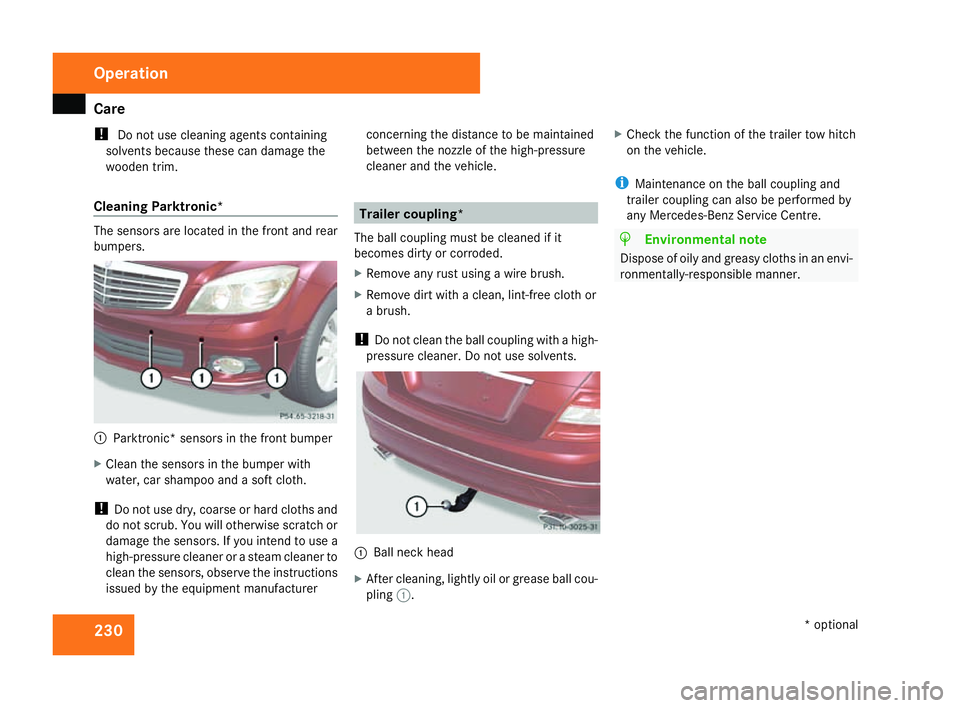
1
Parktronic* sensors in the front bumper
X Clean the sensors in the bumper wit h
water, car shampoo and a soft cloth.
! Do not use dry, coarse or hard cloths and
do not scrub. You will otherwise scratch or
damage the sensors. If you intend to use a
high-pressure cleaner or a steam cleaner to
clean the sensors, observe the instructions
issued by the equipment manufacturer concerning the distance to be maintained
between the nozzle of the high-pressure
cleaner and the vehicle. Trailer coupling*
The ball coupling must be cleaned if it
becomes dirty or corroded.
X Remove any rust using a wire brush.
X Remove dirt with a clean, lint-free cloth or
a brush.
! Do not clean the ball coupling with a high -
pressure cleaner. Do not use solvents.
1 Ball neck hea d
X After cleaning, lightly oil or grease ball cou -
pling 1. X
Check the function of the trailer tow hitch
on the vehicle .
i Maintenance on the ball coupling and
trailer coupling can also be performed by
any Mercedes-Benz Service Centre. H
Environmental not
e
Dispose of oily and greasy cloths in an envi -
ronmentally-responsible manner. Operation
* optional
204_AKB; 2; 3, en-GB
mkalafa,
2007-06-26T23:11:51+02:00 - Seite 230
Page 234 of 377
231
Where will I find...?
...........................232
Display messages ............................. 236
Troubleshooting ................................ 276
Locking/unlocking in an emer-
gency ................................................. 300
Resetting triggered NECK-PRO
head restraints .................................. 303
Changing the batteries .....................304
Changing the bulbs ...........................305
Replacing the wiper blades ..............312
Flat tyre ............................................. 313
Battery ............................................... 324
Jump-starting .................................... 328
Towing and tow-starting ..................329
Fuses .................................................. 332 Practical advice
204_AKB; 2; 3, en-GB
mkalafa,
2007-06-26T23:11:51+02:00 - Seite 231
Page 235 of 377
Where will I find...?
232 Where will I find...?
Warning triangle
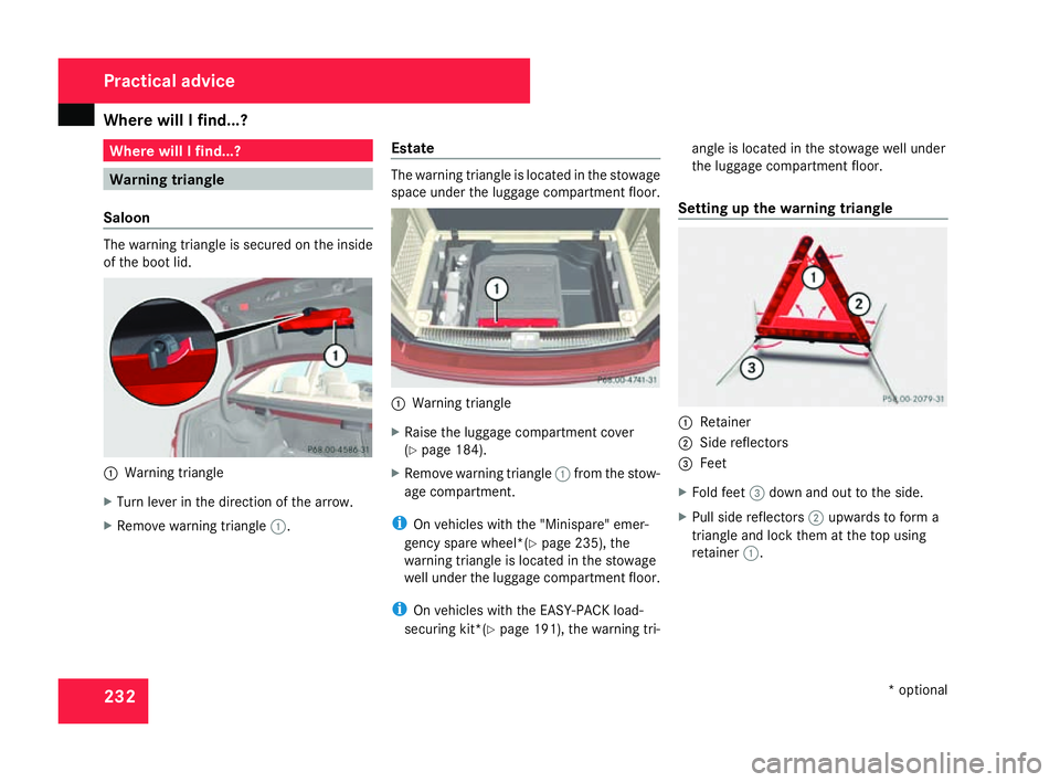
Saloon The warning triangle is secured on the insid
e
of the boot lid. 1
Warning triangle
X Turn lever in the direction of the arrow.
X Remove warning triangle 1. Estat
e The warning triangle is located in the stowage
space under the luggage compartment floor.
1
Warning triangle
X Raise the luggage compartment cover
(Y page 184).
X Remove warning triangle 1from the stow-
age compartment.
i On vehicles with the "Minispare" emer-
gency spare wheel*(Y page 235), the
warning triangle is located in the stowage
well under the luggage compartment floor.
i On vehicles with the EASY-PACK load-
securing kit*( Ypage 191), the warning tri- angle is located in the stowage well under
the luggage compartment floor.
Setting up the warning triangle 1
Retainer
2 Side reflector s
3 Feet
X Fold feet 3down and out to the side.
X Pull side reflectors 2upwards to form a
triangle and lock them at the top using
retainer 1. Practical advice
* optional
204_AKB; 2; 3, en-GB
mkalafa,
2007-06-26T23:11:51+02:00 - Seite 232
Page 237 of 377
Where will I find...?
234
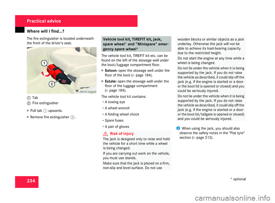
The fire extinguisher is located underneath
the front of the driver's seat.
1
Tab
2 Fire extinguishe r
X Pull tab 1upwards.
X Remove fire extinguisher 2. Vehicle tool kit, TIREFIT kit, jack
,
spare wheel* and "Minispare" emer-
gency spare wheel*
The vehicle tool kit, TIREFIT kit etc. can be
found on the left of the stowage well under
the boot/luggage compartment floor.
X Saloon: open the stowage well under the
floor of the boot (Y page 184).
X Estate: open the stowage well under th e
floor of the luggage compartment
( Y page 184).
The vehicle tool kit contains :
R A towing ey e
R A wheel wrench
R A folding wheel chock
R Spare fuses
R A pair of glove s G
Risk of injury
The jack is designed only to raise and hol d
the vehicle for a short time while a whee l
is being changed.
If you are carrying out work on the vehicle,
you must use stands.
Make sure that the jack is placed on a firm ,
non-slip and level surface. Do not us e wooden blocks or similar objects as a jac
k
underlay. Otherwise the jack will not be
able to achieve its load-bearing capacit y
due to the restricted height.
Do not start the engine at any time while a
wheel is being changed.
Do not lie under the vehicle when it is bein g
supported by the jack. If you do not raise
the vehicle as described, it could slip off the
jack (e.g. if the engine is started or a door
or the boot lid is opened or closed) and you
could be seriously injured.
Do not lie under the vehicle when it is being
supported by the jack. If you do not raise
the vehicle as described, it could slip off the
jack (e.g. if the engine is started or a door
or the boot lid/tailgate is opened or closed)
and you could be seriously injured.
i When using the jack, you should also
observe the safety notes in the "Flat tyre"
section (Y page 313). Practical advice
* optional
204_AKB; 2; 3, en-GB
mkalafa,
2007-06-26T23:11:51+02:00 - Seite 234
Page 238 of 377
Where will I find...?
235
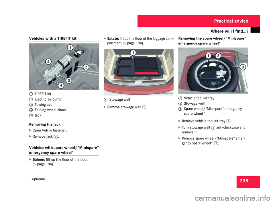
Vehicles with a TIREFIT kit
1
TIREFIT kit
2 Electric air pump
3 Towing eye
4 Folding wheel chock
5 Jack
Removing the jack
X Open Velcro fastener.
X Remove jack 5.
Vehicles with spare wheel/"Minispare "
emergency spare wheel* X
Saloon: lift up the floor of the boot
( Y page 184). X
Estate: lift up the floor of the luggage com -
partment (Y page 184). 1
Stowage well
X Remove stowage well 1. Removing the spare wheel/"Minispare"
emergency spare wheel
* 1
Vehicle tool kit tray
2 Stowage well
3 Spare wheel/"Minispare" emergency
spare wheel *
X Remove vehicle tool kit tray 1.
X Turn stowage well 2anti-clockwise and
remove it.
X Remove spare wheel/"Minispare" emer-
gency spare wheel* 3. Practical advice
* optional
204_AKB; 2; 3, en-GB
mkalafa,
2007-06-26T23:11:51+02:00 - Seite 235
Page 244 of 377
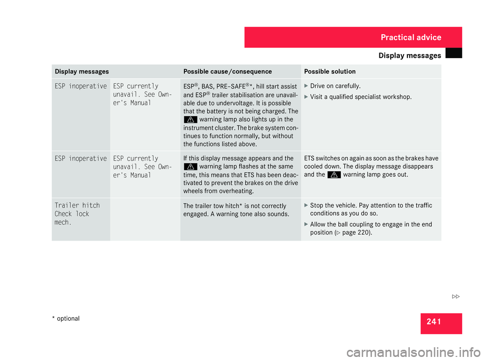
Display
messages 24
1 Display messages Possible cause/consequence Possible solution
ESP inoperative ESP currently
unavail. See Own
-
er's Manual ESP
®
, BAS, PRE–SAFE ®
*, hill start assist
and ESP ®
trailer stabilisation are unavail -
able due to undervoltage. It is possible
that the battery is not being charged. The
v warning lamp also lights up in th e
instrument cluster. The brake system con -
tinues to function normally, but without
the functions listed above . X
Drive on carefully.
X Visit a qualified specialist workshop. ESP inoperative ESP currently
unavail. See Own-
er's Manual If this display message appears and the
v
warning lamp flashes at the same
time, this means that ETS has been deac-
tivated to prevent the brakes on the driv e
wheels from overheating . ETS switches on again as soon as the brakes have
cooled down. The display message disappears
and the
vwarning lamp goes out. Trailer hitch
Check loc
k
mech. The trailer tow hitch* is not correctly
engaged. A warning tone also sounds. X
Stop the vehicle. Pay attention to the traffic
conditions as you do so.
X Allow the ball coupling to engage in the end
position (Y page 220). Practical advice
* optional
204_AKB; 2; 3, en-GB
mkalafa,
2007-06-26T23:11:51+02:00 - Seite 241 Z
Page 252 of 377
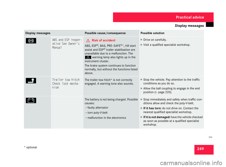
Display
messages 24
9 Display messages Possible cause/consequence Possible solution
- ABS and ESP inoper-
ative See Owner's
Manual
G
Risk of accident
ABS, ESP ®
, BAS, PRE–SAFE ®
*, hill start
assist and ESP ®
trailer stabilisation ar e
unavailable due to a malfunction. The
v warning lamp also lights up in th e
instrument cluster.
The brake system continues to function
normally, but without the functions listed
above. X
Drive on carefully.
X Visit a qualified specialist workshop. \ Trailer tow hitch
Check lock mecha-
nism
The trailer tow hitch* is not correctly
engaged. A warning tone also sounds. X
Stop the vehicle. Pay attention to the traffic
conditions as you do so.
X Allow the ball coupling to engage in the end
position (Y page 220). # The battery is not being charged. Possible
causes:
R
faulty alternator
R torn poly-V-bel t
R malfunction in the electronics X
Stop immediately and safely when traffic con-
ditions allow and check the poly-V-belt.
X If it has torn: do not drive on. Contact th e
nearest qualified specialist workshop .
X If it is not damaged :have the vehicle checked
as soon as possible at a qualified specialist
workshop. Practical advice
* optional
204_AKB; 2; 3, en-GB
mkalafa,
2007-06-26T23:11:51+02:00 - Seite 249 Z