technical data MERCEDES-BENZ CLA COUPE 2016 Owners Manual
[x] Cancel search | Manufacturer: MERCEDES-BENZ, Model Year: 2016, Model line: CLA COUPE, Model: MERCEDES-BENZ CLA COUPE 2016Pages: 345, PDF Size: 12.41 MB
Page 6 of 345
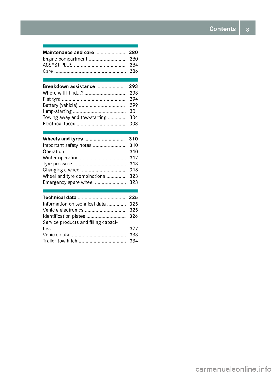
Maintenance and care
......................280
Engine compartment ........................... 280
ASSYST PLUS ...................................... 284
Care ..................................................... 286 Breakdown assistance
.....................293
Where will I find...? .............................. 293
Flat tyre ............................................... 294
Battery (vehicle) .................................. 299
Jump-starting ....................................... 301
Towing away and tow-starting ............. 304
Electrical fuses ................................... .308 Wheels and tyres
.............................. 310
Important safety notes ........................ 310
Operation ............................................ 310
Winter operation .................................. 312
Tyre pressure ....................................... 313
Changing a wheel ................................ 318
Wheel and tyre combinations .............. 323
Emergency spare wheel ....................... 323 Technical data
................................... 325
Information on technical data .............. 325
Vehicle electronics .............................. 325
Identification plates ............................ .326
Service products and filling capaci-
ties ...................................................... 327
Vehicle data ......................................... 333
Trailer tow hitch ................................... 334 Contents
3
Page 11 of 345
Switching on/of
f........................... 120
Switching residual heat on/off ...... 126
Switching the rear window heat-
ing on/of f...................................... 124
Switching the ZONE function
on/of f............................................ 123
THERMOTRONIC (2-zone) auto-
matic climate control ..................... 119
Cockpit
Overview .......................................... 30
COMAND display
Cleaning ......................................... 290
COMAND Online
Switching on/of f........................... 259
Combination switch .......................... 109
Connecting a USB device
See also Digital Owner's Manua l... 259
Consumption statistics (on-board
computer) .......................................... 203
Controller ........................................... 260
Convenience closing feature .............. 90
Convenience opening feature ............ 90
Convenience opening/closing (air-
recirculation mode) ........................... 125
Coolant (engine)
Checking the level ......................... 283
Display message ............................ 231
Important safety notes .................. 332
Temperature (on-board computer, Mercedes-AMG vehicles) ............... 213
Temperature gaug e........................ 201
Warning lamp ................................. 255
Cooling
see Climate control
Copyright ............................................. 29
Cornering light function
Display message ............................ 228
Cruise control
Activation conditions ..................... 163
Cruise control lever ....................... 163
Deactivating ................................... 164
Display message ............................ 237
Driving system ............................... 162
Important safety notes .................. 163
LIM indicator lamp ......................... 163
Selecting ........................................ 163
Setting a speed .............................. 164 Storing and maintaining current
speed ............................................. 163
Cup holder
Centre console .............................. 274
Important safety notes .................. 273
Rear compartment ......................... 274 D
Dashboard see Instrument cluster
Data
see Technical data
Data modem mode
Telephone with Bluetooth ®
(SAP
profile) ........................................... 265
Daytime driving lights
Display message ............................ 230
Function/note s............................. 107
Switching on/off (on-board com-
puter) ............................................. 211
Dealership
see Qualified specialist workshop
Declarations of conformity ................. 26
Diagnostics connection ...................... 27
Diesel .................................................. 330
Digital Owner's Manual
Help ................................................. 23
Introduction ..................................... 23
Digital speedometer ......................... 204
Dipped-beam headlamps
Display message ............................ 228
Replacing bulb s............................. 112
Setting for driving abroad (sym-
metrical) ........................................ 107
Switching on/of f........................... 108
DIRECT SELECT lever
Automatic transmission ................. 144
Display message
Driving systems ............................. 234
Display messages
ASSYST PLUS ................................ 284
Calling up (on-board computer) ..... 216
Engine ............................................ 231
General information ....................... 216
Hiding (on-board computer) ........... 216
Key ................................................ 246
Lights ............................................. 228 8
Index
Page 22 of 345
SPORT handling mode
Deactivating/activating
(Mercedes-AMG vehicles) ................71
Warning lamp ................................. 253
Start-off assist
Activating ....................................... 174
Important safety notes .................. 174
Start/Stop button
Removing ....................................... 134
Starting the engine ........................ 135
Start/stop function
see ECO start/stop function
Starting (engine) ................................ 134
STEER CONTROL ..................................73
Steering
Display message ............................2 45
Steering assistant STEER CON-
TROL
see STEER CONTROL
Steering wheel
Adjusting (manually) ...................... 102
Button overview ............................... 33
Buttons (on-board computer) ......... 201
Cleaning ......................................... 291
Gearshift paddle s........................... 150
Important safety notes .................. 102
Steering wheel gearshift paddles .... 150
Stopwatch (RACETIMER) ................... 214
Stowage compartment
Map pockets .................................. 270
Stowage compartments
Armrest (front) ............................... 269
Armrest (under) ............................. 270
Centre console .............................. 269
Centre console (rear) ..................... 270
Cup holde r..................................... 273
Glove compartment ....................... 269
Important safety information ......... 268
Spectacles compartment ............... 269
Under driver's seat/front-
passenger sea t.............................. 270
Stowage net ....................................... 270
Stowage space
Stowage net ................................... 270
Stowage well beneath the boot
floor .................................................... 272
Summer tyres .................................... 312 Sun visor
............................................ 275
Suspension
Adaptive Damping System ............. 176
Suspension settings
AMG RIDE CONTROL sports sus-
pension .......................................... 175
Switching on media mode
Via the device list .......................... 266 T
Tail lamps Display message ............................ 229
see Lights
Tank
see Fuel tank
Technical data
Capacities ...................................... 327
Information .................................... 325
Trailer load s................................... 334
Tyres/wheels ................................. 323
Vehicle data ................................... 333
Telephone
Accepting a call (multifunction
steering wheel) .............................. 207
Authorising a mobile phone (con-
necting) ......................................... 263
Connecting a Mobile phone (gen-
eral information) ............................ 262
Display message ............................ 246
Introduction ................................... 207
Menu (on-board computer) ............ 207
Number from the phone book ........ 207
Redialling ....................................... 208
Rejecting/ending a call ................. 207
See also Digital Owner's Manua l... 259
Switching between mobile
phones ........................................... 263
Telephone compartment ................ 270
Telephone module with Bluetooth ®
(SAP profile) Activating and connecting the
module ........................................... 264
Charging a mobile phone ............... 266
Connecting the mobile phone ........ 265
Connecting the module via a USB
cable .............................................. 264
Data modem mode ........................ 265 Index
19
Page 29 of 345
Do not attempt to modify the wiring as well as
electronic components or their software.
Always have work on electrical and electronic
components carried out at a qualified special- ist workshop.
If you make any changes to the vehicle elec-
tronics, the general operating permit is ren-
dered invalid.
! There is a risk of damage to the vehicle if:
R the vehicle becomes stuck, e.g. on a high
kerb or an unpaved road
R you drive too fast over an obstacle, e.g. a
kerb, a speed bump or a pothole in the road
R a heavy object strikes the underbody or
parts of the chassis
In situations like this, the body, the under-
body, chassis parts, wheels or tyres could be damaged without the damage being visible.
Components damaged in this way can unex-
pectedly fail or, in the case of an accident, no
longer withstand the strain they are designed
to.
If the underbody panelling is damaged, com-
bustible materials such as leaves, grass or
twigs can gather between the underbody and
the underbody panelling. If these materials
come in contact with hot parts of the exhaust system, they can catch fire.
In such situations, have the vehicle checked
and repaired immediately at a qualified spe-
cialist workshop. If on continuing your jour-
ney you notice that driving safety is impaired,pull over and stop the vehicle immediately,
paying attention to road and traffic condi-
tions. In such cases, consult a qualified spe-
cialist workshop. Declarations of conformity
Wireless vehicle components The following information applies to all compo-
nents of the vehicle and the information sys-
tems and communication devices integrated
into the vehicle that receive and/or transmit
radio waves:
The components of this vehicle that receive
and/or transmit radio waves are compliant with the basic requirements and all other relevant
conditions of Directive 1999/5/EC. You can obtain further information from any Mercedes-
Benz Service Centre.
Electromagnetic compatibility The electromagnetic compatibility of the vehicle
components has been checked and certified
according to the currently valid version of Reg-
ulation ECE-R 10.
Jack Copy and translation of the original declaration
of conformity:
EC declaration of conformity
1. The signatory, as a representative Manufacturer:
BRANO a.s.
74741 Hradec nad Moravicí, Opav-
ská 1000,
Czech Republic
ID no.: 64-387-5933
VAT ID no.: CZ64-387-5933
declares, as our sole responsibility, that the
product:
2.
a) Description:
Jack
Type, number:
A) A 164 580 02 18, A 166 580 01 18
B) A 240 580 00 18
C) A 639 580 02 18
Year of manufacture: 2015
Fulfils all relevant conditions
Directive no. 2006/42/EC
b) Description and purpose of use: The jack is intended only for raising the
specified vehicle according to the operating
instructions affixed to the jack.
3. Reference data of the harmonised stand- ards or specifications
A) ISO 4063, EN ISO 14341-A, DBL
7382.20, MBN 10435, AS 2693
B) ISO 4063, ISO 14341-A, DBL 7392.10,
MBN 10435
C) DBL 7392.10, DBL 8230.10
Technical documentation for the product isheld by the manufacturer. Authorised rep-
resentative for the compilation of the tech-
nical documentation: director of the tech-
nical department at Brano a.s. 26
Operating safetyIntroduction
Page 31 of 345
vehicle. This particularly applies to work rele-
vant to safety.
Observe the notes in the Service Booklet.
Always have the following work carried out at a
qualified specialist workshop:
R work relevant to safety
R service and maintenance work
R repair work
R modifications, installations and conversions
R work on electronic components
Mercedes-Benz recommends that you use a
Mercedes-Benz Service Centre. Vehicle registration
Mercedes-Benz may ask its Service Centres to
carry out technical inspections on certain vehi-
cles. The quality or safety of the vehicle is
improved as a result of the inspection.
Mercedes-Benz can only inform you about vehi-
cle checks if it has your registration data.
It is possible that your vehicle has not yet been
registered in your name in the following cases:
R if your vehicle was not purchased at an
authorised specialist dealer
R if your vehicle has not yet been inspected at a
Mercedes-Benz Service Centre
It is advisable to register your vehicle with a
Mercedes-Benz Service Centre.
Inform Mercedes-Benz as soon as possible
about any change in address or vehicle owner-
ship. You can do this at a Mercedes-Benz Ser-
vice Centre, for example. Correct use
If you remove any warning stickers, you or oth-
ers could fail to recognise certain dangers.
Leave warning stickers in position.
Observe the following information when driving
your vehicle:
R the safety notes in this manual
R technical data for the vehicle
R traffic rules and regulations
R laws and safety standards pertaining to motor
vehicles Implied warranty
! Follow the instructions in this manual about
the proper operation of your vehicle as well as about possible vehicle damage. Damage to
your vehicle that arises from culpable contra- ventions against these instructions are not
covered either by Mercedes-Benz implied
warranty or by the New or Used-Vehicle War-
ranty. QR code for rescue card
The QR code is secured in the fuel filler flap and
on the opposite side on the B-pillar. In the event of an accident, rescue services can use the QR
code to quickly find the appropriate rescue card
for your vehicle. The current rescue card con-
tains, in a compact form, the most important
information about your vehicle, e.g. the routing
of the electric cables.
You can find more information under
www.mercedes-benz.de/qr-code. Data stored in the vehicle
Many of the electronic components in your vehi- cle can store data.
These data memories temporarily or perma-
nently store technical information about:
R the vehicle's operating state
R events
R faults
In general, this technical information docu-
ments the state of a component, a module, a
system or the surroundings.
This includes, for example:
R operating conditions of system components,
e.g. fluid levels
R status messages concerning the vehicle and
its individual components, e.g. number of
wheel revolutions/speed, deceleration in
movement, lateral acceleration, accelerator
pedal position
R malfunctions and defects in important system
components, e.g. lights, brakes
R vehicle reactions and operating conditions in
special driving situations, e.g. airbag deploy- 28
Data stored in the vehicleIntroduction
Page 32 of 345
ment, intervention of stability control sys-
tems
R ambient conditions, e.g. outside temperature
These data are of an exclusively technical nature
and can be used to:
R assist in detecting and rectifying faults and
defects
R analyse vehicle functions, e.g. after an acci-
dent
R optimise vehicle functions
The data cannot be used to trace the vehicle's
movements.
When your vehicle is serviced, technical infor-
mation can be read from the event data memory
and fault data memory.
Services include, for example:
R repair services
R service processes
R warranty events
R quality assurance
The information is read out by employees of the service network (including the manufacturer)
using special diagnostic testers. You can obtain
more information there, if required.
After a fault has been rectified, the information
is deleted from the fault memory or is continu-
ally overwritten.
During vehicle operation, certain situations may arise in which these technical data – in conjunc-
tion with other information and, if applicable,
after consultation with an approved assessor –
may be linked to an individual person.
Examples include:
R accident reports
R damage to the vehicle
R witness statements
Further additional functions that have been con-
tractually agreed upon with the customer allow
certain vehicle data to be conveyed by the vehi-
cle as well. The additional functions include, for example, vehicle location in the event of an
emergency. Copyright information
General information
Information on licences for free and open-
source software used in your vehicle and its electronic components is available on the fol-
lowing website:
http://www.mercedes-benz.com/opensource Copyright information
29Introduction Z
Page 198 of 345
G
WARNING
If the maximum permissible load for a carrier system is exceeded, the carrier could come
loose from the vehicle and endanger other
road users. There is a risk of an accident and injury.
Never exceed the maximum permissible load
when using a carrier.
! If you have a trailer tow hitch retrofitted,
changes to the engine cooling system may be necessary, depending on the vehicle type.
If you have a trailer tow hitch retrofitted,
observe the anchorage points on the chassis.
Retrofitting a trailer tow hitch is only permissible
if a trailer load is specified in your vehicle docu-
ments. If this is not the case, then the vehicle is not approved for towing a trailer.
For more information, please contact a qualifiedspecialist workshop.
Exceeding the maximum permissible nose-
weight of the trailer drawbar on the ball coupling
may cause damage to the following:
R your vehicle
R trailer
R ball coupling
R trailer tow hitch
The vehicle/trailer combination could become
unstable.
The vehicle/trailer combination could also
become unstable if the noseweight used is lower than the minimum permissible noseweight.
To avoid hazardous situations:
R make sure to check the noseweight before
each journey
R the noseweight should be as close as possible
to the maximum noseweight
R do not exceed the maximum permissible
noseweight
R the noseweight must not be lower than the
minimum permissible noseweight
Make sure that the following values are not
exceeded:
R the permissible noseweight
R the permissible trailer load R
the permissible rear axle load of the towing
vehicle
R the maximum permissible gross vehicle
weight of both the towing vehicle and the
trailer
The applicable permissible values, which must
not be exceeded, can be found:
R in your vehicle documents
R on the identification plates of the trailer tow
hitch and the trailer
R on the vehicle identification plate
If the values differ, the lowest value applies.
You will find the values approved by the manu-
facturer on the identification plates and for the
towing vehicle under "Technical data"
(Y page 334). G
WARNING
If you release the ball coupling or it does not
engage correctly when folding in, it will swing out. Within pivoting range of the ball coupling,
there is an increased risk of an accident and
injury.
Only release the ball coupling if the pivoting
range is unobstructed. Always make sure that the ball coupling engages when folding in.
When reversing the towing vehicle, make sure
there is nobody between the trailer and the vehi- cle.
Couple and uncouple the trailer carefully. If youdo not couple the trailer to the towing vehicle
correctly, the trailer could become detached.
When towing a trailer, your vehicle's handling
characteristics will be different to when driving
without a trailer.
The vehicle/trailer combination:
R is heavier
R is restricted in its acceleration and gradient-
climbing capability
R has an increased braking distance
R is affected more by strong crosswinds
R demands more sensitive steering
R has a larger turning circle
This can impair the vehicle's handling charac-
teristics. Adapt your driving style accordingly.
Maintain a safe distance. Drive carefully.
When towing a trailer, always adjust your speed to the current road and weather conditions. Do Towing a trailer
195Driving and parking Z
Page 199 of 345
not exceed the maximum permissible speed for
your vehicle/trailer combination. Notes on towing a trailer
General notes Trailer towing is not possible on the following
models:
R CLA 180 d BlueEFFICIENCY Edition
R CLA 250 Sport
R CLA 250 Sport 4MATIC
R Mercedes‑AMG CLA 45 4MATIC
When towing a trailer, set the tyre pressure on
the rear axle of the towing vehicle for the max-
imum load. Further information on the tyre pres-
sure table in the fuel filler flap (Y page 313).
Please note that when towing a trailer, the fol-
lowing driving systems have limited availability
or are not available at all.
R Parking Assist PARKTRONIC (Y page 177)
R Blind Spot Assist (Y page 192)
The height of the ball coupling changes with the
load of the vehicle. If necessary, use a trailer
with a height-adjustable drawbar.
You will find fitting dimensions and loads under "Technical data" (Y page 334).
Driving tips Observe the notes on ESP
®
trailer stabilisation
(Y page 72).
The maximum permissible speed for vehicle/
trailer combinations depends on the type of
trailer. Before beginning the journey, check the
trailer's documents to see what the maximum
permitted speed is. Observe the legally prescri-
bed maximum speed in the relevant country.
For certain Mercedes-Benz vehicles, the maxi-
mum permissible rear axle load is increased
when towing a trailer. See the "Technical data"
section to find out whether this applies to your
vehicle. If you utilise any of the added maximum rear axle load when towing a trailer, the vehicle/
trailer combination may not exceed a maximum speed of 100 km/h for reasons concerning the
operating permit. This also applies in countries
in which the permissible maximum speed for
vehicle/trailer combinations is above
100 km/h. When towing a trailer, your vehicle's handling
characteristics will be different to when driving
without a trailer and the vehicle will consume
more fuel.
Shift into a lower gear in good time on long and steep downhill gradients. For vehicles with auto-
matic transmission, you need to have selected
manual drive program M(Y page 150).
This also applies if you have activated cruise
control, SPEEDTRONIC or Distance Pilot
DISTRONIC.
This will use the braking effect of the engine, so
less braking will be required to maintain the
vehicle speed. This relieves the load on the
brake system and prevents the brakes from
overheating and wearing too quickly. If you need additional braking, depress the brake pedal
repeatedly rather than continuously.
Briefly depressing the accelerator pedal on
downhill gradients while the manual drive pro-
gram Mis temporarily activated (vehicles with
automatic transmission): the automatic trans-
mission may switch back to the last active auto-
matic drive program Eor S. The automatic trans-
mission may shift to a higher gear. This can
reduce the engine's braking effect.
Driving tips R
Maintain a greater distance to the vehicle in
front than when driving without a trailer.
R Avoid braking abruptly. If possible, brake gen-
tly at first to allow the trailer to run on. Then,
increase the braking force rapidly.
R The values given for gradient-climbing capa-
bilities from a standstill refer to sea level.
When driving in mountainous areas, note that
the power output of the engine, and conse-
quently the vehicle's gradient-climbing capa-
bility from a standstill, decrease with increas-
ing altitude.
If the trailer swings from side to side:
X Do not accelerate under any circumstances
X Do not countersteer
X Brake, if necessary 196
Towing a trailerDriving an
d parking
Page 276 of 345
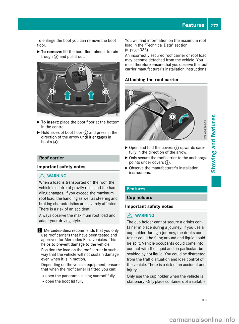
To enlarge the boot you can remove the boot
floor.
X To remove: lift the boot floor almost to rain
trough ;and pull it out. X
To insert: place the boot floor at the bottom
in the centre.
X Hold sides of boot floor =and press in the
direction of the arrow until it engages in
hooks ?. Roof carrier
Important safety notes G
WARNING
When a load is transported on the roof, the
vehicle's centre of gravity rises and the han-
dling changes. If you exceed the maximum
roof load, the handling as well as steering and braking characteristics are severely affected.
There is a risk of an accident.
Always observe the maximum roof load and
adapt your driving style.
! Mercedes-Benz recommends that you only
use roof carriers that have been tested and
approved for Mercedes-Benz vehicles. This
helps to prevent damage to the vehicle.
Position the load on the roof carrier in such a way that the vehicle will not sustain damage
even when it is in motion.
Depending on the vehicle equipment, ensure
that when the roof carrier is fitted you can:
R open the panorama sliding sunroof fully
R open the boot lid fully You will find information on the maximum roof
load in the "Technical Data" section
(Y page 333).
An incorrectly secured roof carrier or roof load
may become detached from the vehicle. You
must therefore ensure that you observe the roof
carrier manufacturer's installation instructions.
Attaching the roof carrier X
Open and fold the covers :upwards care-
fully in the direction of the arrow.
X Only secure the roof carrier to the anchorage
points under covers :.
X Observe the manufacturer's installation
instructions. Features
Cup holders
Important safety notes G
WARNING
The cup holder cannot secure a drinks con-
tainer in place during a journey. If you use a
cup holder during a journey, the drinks con-
tainer could be flung around and liquid could
be spilt. Vehicle occupants could come into
contact with the liquid and, in particular, be
scalded by hot liquid. You could be distracted
from the traffic situation and lose control of
the vehicle. There is a risk of an accident and
injury.
Only use the cup holder when the vehicle is
stationary. Only place containers of a suitable Features
273Stowing and features
Z
Page 328 of 345
Information on technical data
i The technical data were determined in
accordance with EU Directives. All data apply
to the vehicle's standard equipment. The data may therefore differ for vehicles with optional
equipment. You can obtain further informa-
tion from a Mercedes-Benz Service Centre. Vehicle electronics
Tampering with the engine electron-
ics
! Only have work carried out on the engine
electronics and its associated parts, such as
control units, sensors, actuating components
and connector leads, at a qualified specialist
workshop. Vehicle components may other-
wise wear more quickly and the vehicle's
operating permit may be invalidated. Retrofitting two-way radios and
mobile phones (RF transmitters) G
WARNING
If RF transmitters are tampered with or not
properly retrofitted, the electromagnetic radi- ation they emit can interfere with the vehicle
electronics. This may jeopardise the opera-
tional safety of the vehicle. There is a risk of an
accident.
You should have all work on electrical and
electronic components carried out at a quali-
fied specialist workshop. G
WARNING
If you operate RF transmitters incorrectly in
the vehicle, the electromagnetic radiation
could interfere with the vehicle electronics,
e.g.:
R if the RF transmitter is not connected to an
exterior aerial
R the exterior aerial has been fitted incor-
rectly or is not a low-reflection type
This could jeopardise the operating safety of
the vehicle. There is a risk of an accident. Have the low-reflection exterior aerial fitted at
a qualified specialist workshop. When oper-
ating RF transmitters in the vehicle, always
connect them to the low-reflection exterior
aerial.
! The operating permit may be invalidated if
the instructions for installation and use of RF
transmitters are not observed.
In particular, the following conditions must be complied with:
R only approved wavebands may be used.
R observe the maximum permissible output
in these wavebands.
R only approved aerial positions may be
used.
Excessive levels of electromagnetic radiation
may cause damage to your health and to the
health of others. The use of an exterior aerial
takes into consideration the scientific discus-
sion surrounding the possible health risk posed
by electromagnetic fields.
Observe the notes on operating mobile phones
(Y page 277).
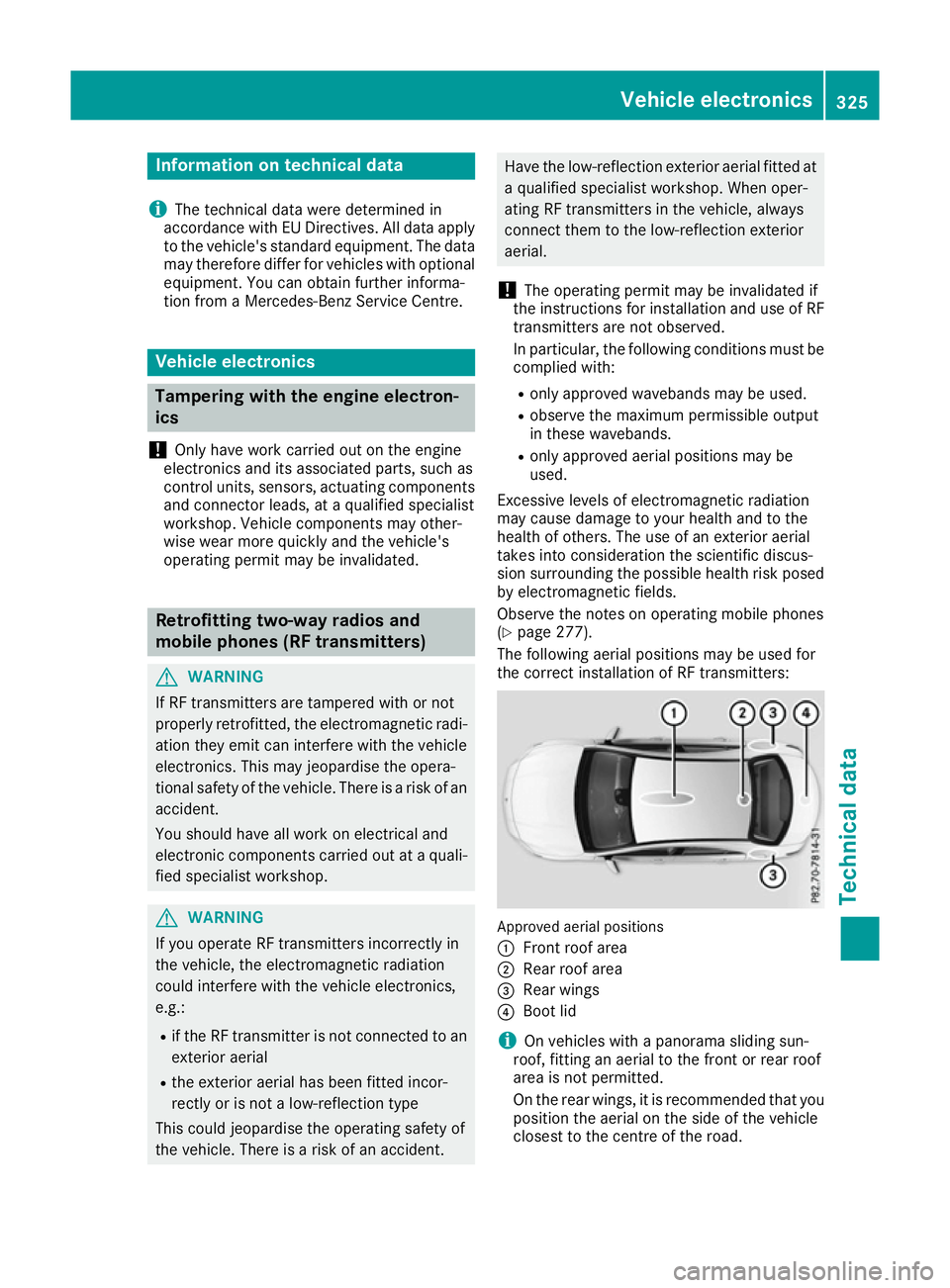
The following aerial positions may be used for
the correct installation of RF transmitters: Approved aerial positions
:
Front roof area
; Rear roof area
= Rear wings
? Boot lid
i On vehicles with a panorama sliding sun-
roof, fitting an aerial to the front or rear roof
area is not permitted.
On the rear wings, it is recommended that you
position the aerial on the side of the vehicle
closest to the centre of the road. Vehicle electronics
325Technical data Z