tow bar MERCEDES-BENZ E-CLASS COUPE 2015 User Guide
[x] Cancel search | Manufacturer: MERCEDES-BENZ, Model Year: 2015, Model line: E-CLASS COUPE, Model: MERCEDES-BENZ E-CLASS COUPE 2015Pages: 345, PDF Size: 11.42 MB
Page 284 of 345
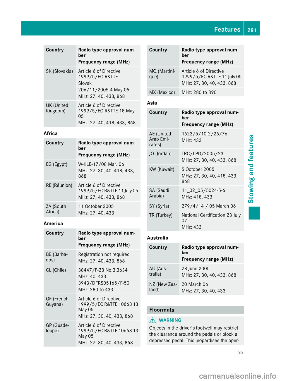
Country Radio type approval num-
ber
Frequency range (MHz)
SK (Slovakia) Article 6 of Directive
1999/5/EC R&TTE
Slovak
206/11/2005 4 May 05
MHz: 27, 40, 433, 868 UK (United
Kingdom) Article 6 of Directive
1999/5/EC R&TTE 18 May
05
MHz: 27, 40, 418, 433, 868
Africa
Country Radio type approval num-
ber
Frequency range (MHz)
EG (Egypt) W-KLE-17/08 Mar. 06
MHz: 27, 30, 40, 418, 433,
868
RE (Réunion) Article 6 of Directive
1999/5/EC R&TTE 11 July 05
MHz: 27, 40, 433, 868 ZA (South
Africa) 11 October 2005
MHz: 27, 40, 433
America
Country Radio type approval num-
ber
Frequency range (MHz)
BB (Barba-
dos) Registration not required
MHz: 27, 40, 433, 868
CL (Chile) 38447/F-23 No.3.3634
MHz: 40, 433
3943/DFRS05165/F-50
MHz: 280 to 433
GF (French
Guyana) Article 6 of Directive
1999/5/EC R&TTE 10668 13
May 05
MHz: 27, 30, 40, 433, 868 GP (Guade-
loupe) Article 6 of Directive
1999/5/EC R&TTE 10668 13
May 05
MHz: 27, 30, 40, 433, 868 Country Radio type approval num-
ber
Frequency range (MHz)
MQ (Martini-
que) Article 6 of Directive
1999/5/EC R&TTE 11 July 05
MHz: 27, 30, 40, 433, 868 MX (Mexico) MHz: 280 to 390
Asia
Country Radio type approval num-
ber
Frequency range (MHz)
AE (United
Arab Emi-
rates) 1623/5/10-2/26/76
MHz: 433
JO (Jordan) TRC/LPD/2005/23
MHz: 27, 30, 40, 433, 868
KW (Kuwait) 5 October 2005
MHz: 27, 30, 40, 418, 433,
868
SA (Saudi
Arabia) 11_02_05/5024-5-6
MHz: 418, 433
SY (Syria) 279/4/14 / 05 March 06
TR (Turkey) National Certification 23 July
07
MHz: 433
Australia
Country Radio type approval num-
ber
Frequency range (MHz)
AU (Aus-
tralia) 28 June 2005
MHz: 27, 30, 40, 433, 868
NZ (New Zea-
land) 20 March 06
MHz: 27, 30, 40, 433
Floormats
G
WARNING
Objects in the driver's footwell may restrict
the clearance around the pedals or block a
depressed pedal. This jeopardises the oper- Features
281Stowing and features
Z
Page 303 of 345
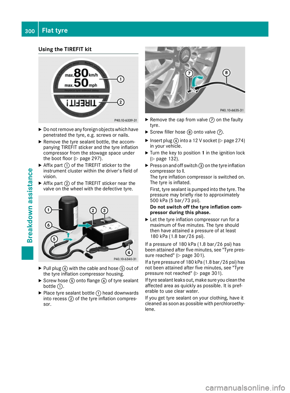
Using the TIREFIT kit
X
Do not remove any foreign objects which have
penetrated the tyre, e.g. screws or nails.
X Remove the tyre sealant bottle, the accom-
panying TIREFIT sticker and the tyre inflation
compressor from the stowage space under
the boot floor (Y page 297).
X Affix part :of the TIREFIT sticker to the
instrument cluster within the driver's field of
vision.
X Affix part ;of the TIREFIT sticker near the
valve on the wheel with the defective tyre. X
Pull plug ?with the cable and hose Aout of
the tyre inflation compressor housing.
X Screw hose Aonto flange Bof tyre sealant
bottle :.
X Place tyre sealant bottle :head downwards
into recess ;of the tyre inflation compres-
sor. X
Remove the cap from valve Con the faulty
tyre.
X Screw filler hose Donto valve C.
X Insert plug ?into a 12 V socket (Y page 274)
in your vehicle.
X Turn the key to position 1in the ignition lock
(Y page 132).
X Press on and off switch =on the tyre inflation
compressor to I.
The tyre inflation compressor is switched on.
The tyre is inflated.
First, tyre sealant is pumped into the tyre. The pressure may briefly rise to approximately
500 kPa (5 bar/73 psi).
Do not switch off the tyre inflation com-
pressor during this phase.
X Let the tyre inflation compressor run for a
maximum of five minutes. The tyre should
then have attained a pressure of at least
180 kPa (1.8 bar/26 psi).
If a pressure of 180 kPa (1.8 bar/26 psi) has
been attained after five minutes, see "Tyre pres-
sure reached" (Y page 301).
If a tyre pressure of 180 kPa (1.8 bar/26 psi) has not been attained after five minutes, see "Tyre
pressure not reached" (Y page 301).
If tyre sealant leaks out, make sure you clean the
affected area as quickly as possible. It is pref-
erable to use clear water.
If you get tyre sealant on your clothing, have it
cleaned as soon as possible with perchloroethy- lene. 300
Flat tyreBreakdown assistance
Page 304 of 345
Tyre pressure not reached
If a pressure of 180 kPa (1.8 bar/26 psi) has not
been attained after five minutes:
X Switch off the tyre inflation compressor.
X Unscrew the filler hose from the valve of the
faulty tyre.
Please note that tyre sealant may leak out
when unscrewing the filler hose.
X Very slowly drive forwards or reverse approx-
imately 10 m.
X Pump up the tyre again.
After a maximum of five minutes the tyre
pressure must be at least 180 kPa (1.8 bar/
26 psi). G
WARNING
If the required tyre pressure is not reached
after the specified time, the tyre is too badly
damaged. The tyre sealant cannot repair the
tyre in this instance. Damaged tyres and a tyre pressure that is too low can significantly
impair the vehicle's braking and driving char-
acteristics. There is a risk of accident.
Do not continue driving. Contact a qualified
specialist workshop.
Tyre pressure reached G
WARNING
A tyre temporarily sealed with tyre sealant
impairs the driving characteristics and is not
suitable for higher speeds. There is a risk of
accident.
You should therefore adapt your driving style
accordingly and drive carefully. Do not exceed the specified maximum speed with a tyre that
has been repaired using tyre sealant.
The maximum speed for a tyre sealed with tyre
sealant is 80 km/h. The upper part of the
TIREFIT sticker must be affixed to the instru-
ment cluster where it will be easily seen by the
driver.
! After use, excess tyre sealant may run out of
the filler hose. This could cause stains.
Therefore, place the tyre sealant bottle with
filler hose in the plastic bag which is con-
tained the TIREFIT kit. H
Environmental note
Have the used tyre sealant bottle disposed of professionally, e.g. at a qualified specialist
workshop.
If a tyre pressure of 180 kPa (1.8 bar/26 psi) has been attained after five minutes:
X Switch off the tyre inflation compressor.
X Unscrew the filler hose from the valve of the
faulty tyre.
X Stow the tyre sealant bottle, the tyre inflation
compressor and the warning triangle.
X Pull away immediately.
X Stop after driving for approximately ten
minutes and check the tyre pressure with the
tyre inflation compressor.
The tyre pressure must now be at least
130 kPa (1.3 bar/19 psi). G
WARNING
If the required tyre pressure is not reached
after driving for a short period, the tyre is too badly damaged. The tyre sealant cannot
repair the tyre in this instance. Damaged tyres and a tyre pressure that is too low can signif-
icantly impair the vehicle's braking and driv-
ing characteristics. There is a risk of accident.
Do not continue driving. Contact a qualified
specialist workshop.
i In your vehicle, you will find a sticker with
the Mercedes-Benz Service24h telephone
number, e.g. on the B-pillar on the driver's
side.
X Correct the tyre pressure if it is still at least
130 kPa (1.3 ba r/19 psi). See the tyre pres-
sure table on the fuel filler flap for values.
X To increase the tyre pressure: switch on
the tyre inflation compressor. Flat tyre
301Breakdown assistance Z
Page 310 of 345
X
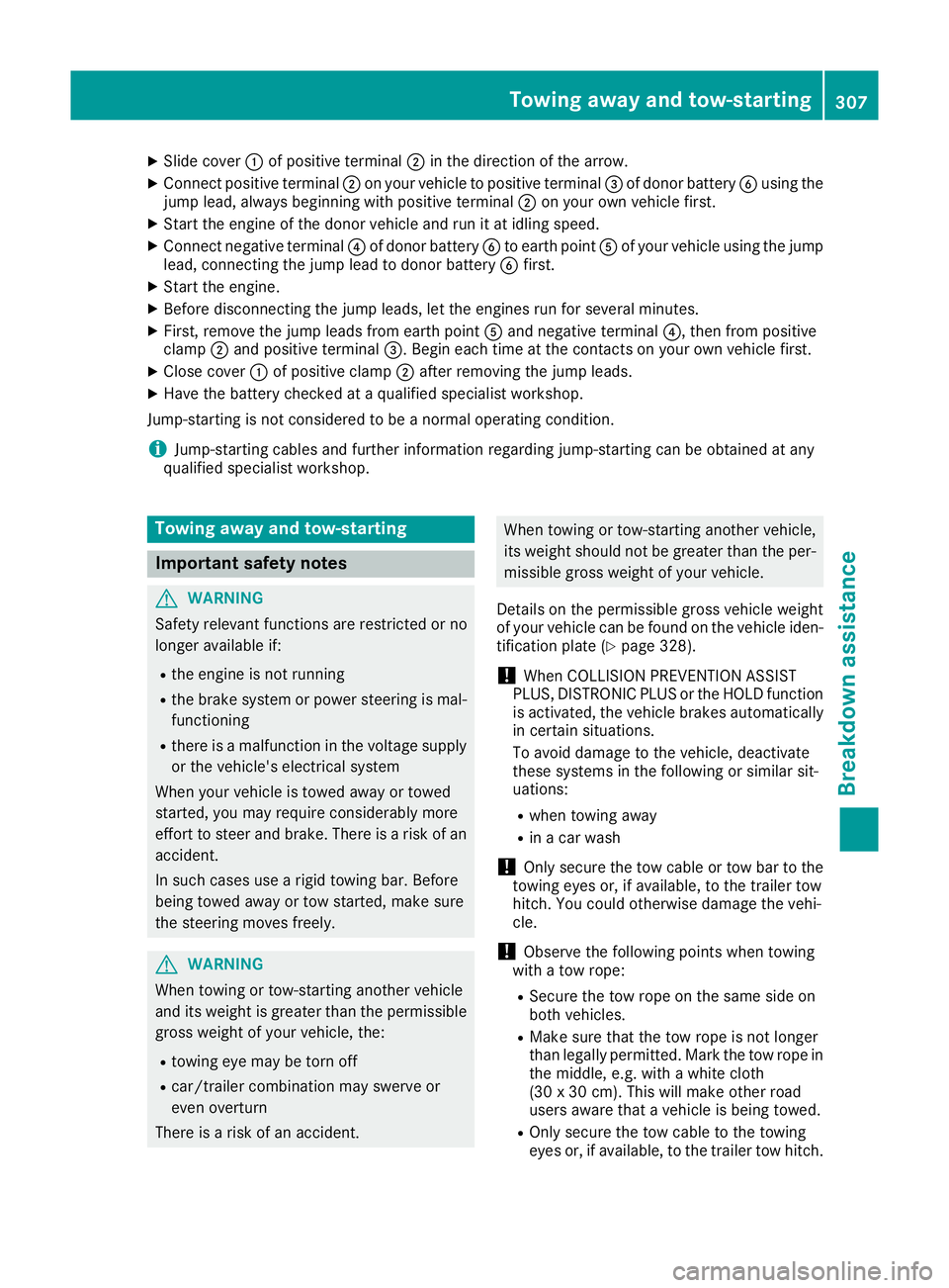
Slide cover :of positive terminal ;in the direction of the arrow.
X Connect positive terminal ;on your vehicle to positive terminal =of donor battery Busing the
jump lead, always beginning with positive terminal ;on your own vehicle first.
X Start the engine of the donor vehicle and run it at idling speed.
X Connect negative terminal ?of donor battery Bto earth point Aof your vehicle using the jump
lead, connecting the jump lead to donor battery Bfirst.
X Start the engine.
X Before disconnecting the jump leads, let the engines run for several minutes.
X First, remove the jump leads from earth point Aand negative terminal ?, then from positive
clamp ;and positive terminal =. Begin each time at the contacts on your own vehicle first.
X Close cover :of positive clamp ;after removing the jump leads.
X Have the battery checked at a qualified specialist workshop.
Jump-starting is not considered to be a normal operating condition.
i Jump-starting cables and further information regarding jump-starting can be obtained at any
qualified specialist workshop. Towing away and tow-starting
Important safety notes
G
WARNING
Safety relevant functions are restricted or no
longer available if:
R the engine is not running
R the brake system or power steering is mal-
functioning
R there is a malfunction in the voltage supply
or the vehicle's electrical system
When your vehicle is towed away or towed
started, you may require considerably more
effort to steer and brake. There is a risk of an
accident.
In such cases use a rigid towing bar. Before
being towed away or tow started, make sure
the steering moves freely. G
WARNING
When towing or tow-starting another vehicle
and its weight is greater than the permissible gross weight of your vehicle, the:
R towing eye may be torn off
R car/trailer combination may swerve or
even overturn
There is a risk of an accident. When towing or tow-starting another vehicle,
its weight should not be greater than the per-
missible gross weight of your vehicle.
Details on the permissible gross vehicle weight
of your vehicle can be found on the vehicle iden-
tification plate (Y page 328).
! When COLLISION PREVENTION ASSIST
PLUS, DISTRONIC PLUS or the HOLD function is activated, the vehicle brakes automatically
in certain situations.
To avoid damage to the vehicle, deactivate
these systems in the following or similar sit-
uations:
R when towing away
R in a car wash
! Only secure the tow cable or tow bar to the
towing eyes or, if available, to the trailer tow
hitch. You could otherwise damage the vehi-
cle.
! Observe the following points when towing
with a tow rope:
R Secure the tow rope on the same side on
both vehicles.
R Make sure that the tow rope is not longer
than legally permitted. Mark the tow rope in
the middle, e.g. with a white cloth
(30 x 30 cm). This will make other road
users aware that a vehicle is being towed.
R Only secure the tow cable to the towing
eyes or, if available, to the trailer tow hitch. Towing away and tow-starting
307Breakdown assistance Z
Page 312 of 345
X
Remove cover :from the opening.
X Screw in the towing eye clockwise as far as it
will go and tighten it.
Vehicles with a trailer tow hitch do not have a
bracket at the back for the screw-in towing eye.
Connect the towbar to the trailer tow hitch
(Y page 202).
Removing the towing eye X
Loosen the towing eye and unscrew it.
X Position cover :on top of the bumper and
press it in at the bottom until it engages.
X Place the towing eye in the vehicle tool kit. Towing the vehicle with both axles on
the ground
It is important that you observe the safety
instructions when towing away your vehicle
(Y page 307).
X Turn the key to position 2in the ignition lock.
X When the vehicle is stationary, depress the
brake pedal and keep it depressed.
X Vehicles with manual transmission:
depress the clutch pedal fully and engage
neutral.
or X Vehicles with automatic transmission:
shift the transmission to position N.
X Release the brake pedal.
X Release the parking brake.
In order to signal a change of direction when
towing the vehicle with the hazard warning
lamps switched on, use the combination switch as usual. In this case, only the turn signals for
the desired direction flash. When you reset the
combination switch, the hazard warning lamps
start flashing again. Towing the vehicle away with the rear
axle raised
! Vehicles with automatic transmission must
not be towed with the rear axle raised. The
car/trailer combination may otherwise
swerve or even overturn.
! The ignition must be switched off if you are
towing the vehicle with the rear axle raised. Intervention by ESP
®
could otherwise dam-
age the brake system.
X Switch on the hazard warning lamps
(Y page 108).
X Move the front wheels to the straight-ahead
position.
X Turn the key in the ignition lock to position 0
and remove the key from the ignition lock.
X When leaving the vehicle, take the key with
you.
When towing your vehicle away with the rear
axle raised, it is important that you observe the
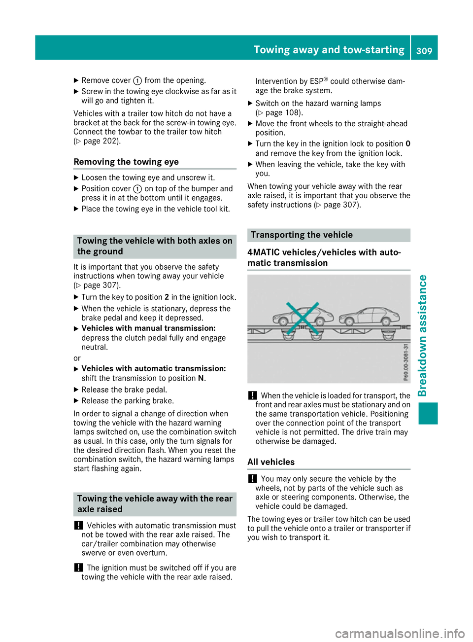
safety instructions (Y page 307). Transporting the vehicle
4MATIC vehicles/vehicles with auto-
matic transmission !
When the vehicle is loaded for transport, the
front and rear axles must be stationary and on
the same transportation vehicle. Positioning
over the connection point of the transport
vehicle is not permitted. The drive train may
otherwise be damaged.
All vehicles !
You may only secure the vehicle by the
wheels, not by parts of the vehicle such as
axle or steering components. Otherwise, the
vehicle could be damaged.
The towing eyes or trailer tow hitch can be used to pull the vehicle onto a trailer or transporter if
you wish to transport it. Towing away and tow-starting
309Breakdown assistance Z
Page 313 of 345
X
Vehicles with manual transmission:
depress the clutch pedal fully and engage
neutral.
X Vehicles with automatic transmission:
turn the key to position
2in the ignition lock.
X Shift the automatic transmission to position
N.
As soon as the vehicle is loaded: X Prevent the vehicle from rolling away by
applying the parking brake.
X Vehicles with manual transmission:
depress the clutch pedal fully and engage first
or reverse gear.
X Vehicles with automatic transmission:
shift the automatic transmission to position
P.
X Turn the key to position 0in the ignition lock
and remove it.
X Secure the vehicle. Notes for 4MATIC vehicles
! Vehicles with 4MATIC must not be towed
with the front or rear axle raised; otherwise,
the transmission may be damaged.
If the vehicle has transmission damage or dam-
age to the front or rear axle, have it transported on a transporter or trailer.
In the event of damage to the electrical sys-
tem
If the battery is defective, the automatic trans-
mission will be locked in position P. To shift the
automatic transmission to position N, you must
provide power to the vehicle's electrical system in the same way as when jump-starting
(Y page 305).
Have the vehicle transported on a transporter or
trailer. Tow-starting (emergency engine
starting)
! Vehicles with automatic transmission must
not be tow-started. The transmission may
otherwise be damaged.
i You can find information on "Jump-starting"
under (Y page 305). Before tow-starting, the following conditions
must be fulfilled:
R the battery is connected
R the engine has cooled down
R the exhaust system has cooled down
When tow-starting, it is important that you
observe the safety notes (Y page 307) and the
legal requirements in each respective country.
X Switch on the hazard warning lamps
(Y page 108).
X Fit the towing eye (Y page 308).
X Secure the rigid towing bar or the towing
rope.
X Depress the brake pedal and keep it
depressed.
X Turn the key to position 2in the ignition lock.
X Depress the clutch pedal fully, engage second
gear and continue to keep the clutch pedal
fully depressed.
X Release the brake pedal.
X Tow-start the vehicle.
X Release the clutch pedal slowly, do not
depress the accelerator pedal while doing so.
X When the engine has been started, immedi-
ately depress the clutch pedal fully and shift
to neutral.
X Pull over at a suitable place and stop the vehi-
cle safely, paying attention to road and traffic
conditions.
X Depress the parking brake.
X Remove the rigid towing bar or towing rope.
X Remove the towing eye (Y page 309).
X Switch off the hazard warning lamps. Electrical fuses
Important safety notes
G
WARNING
If you manipulate, bridge or replace a faulty
fuse with a fuse of a higher amperage, the
electric cables could be overloaded. This may result in a fire. There is a risk of an accident
and injury.
Always replace faulty fuses with specified new fuses of the correct amperage. 310
Electrical fusesBreakdown assistance
Page 339 of 345
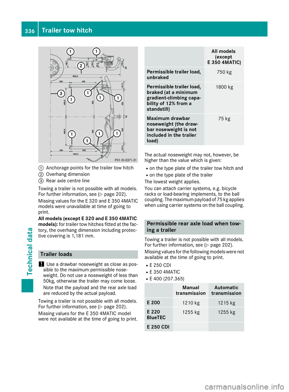
:
Anchorage points for the trailer tow hitch
; Overhang dimension
= Rear axle centre line
Towing a trailer is not possible with all models.
For further information, see (Y page 202).
Missing values for the E 320 and E 350 4MATIC
models were unavailable at time of going to
print.
All models (except E 320 and E 350 4MATIC
models): for trailer tow hitches fitted at the fac-
tory, the overhang dimension including protec-
tive covering is 1,181 mm. Trailer loads
! Use a drawbar noseweight as close as pos-
sible to the maximum permissible nose-
weight. Do not use a noseweight of less than
50kg, otherwise the trailer may come loose.
Note that the payload and the rear axle load
are reduced by the actual payload.
Towing a trailer is not possible with all models.
For further information, see (Y page 202).
Missing values for the E 350 4MATIC model
were not available at the time of going to print. All models
(except
E 350 4MATIC) Permissible trailer load,
unbraked 750 kg
Permissible trailer load,
braked (at a minimum
gradient-climbing capa-
bility of 12% from a
standstill) 1800 kg
Maximum drawbar
noseweight (the draw-
bar noseweight is not
included in the trailer
load)
75 kg
The actual noseweight may not, however, be
higher than the value which is given:
R on the type plate of the trailer tow hitch and
R on the type plate of the trailer
The lowest weight applies.
You can attach carrier systems, e.g. bicycle
racks or load-bearing implements, to the ball
coupling. The maximum payload of 75 kg applies
when using carrier systems on the ball coupling. Permissible rear axle load when tow-
ing a trailer
Towing a trailer is not possible with all models.
For further information, see (Y page 202).
Missing values for the following models were not
available at the time of going to print.
R E 250 CDI
R E 350 4MATIC
R E 400 (207.365) Manual
transmission Automatic
transmission E 200
1210 kg 1215 kg
E 220
BlueTEC
1255 kg 1255 kg
E 250 CDI336
Trailer tow hitchTechnical data