key MERCEDES-BENZ GL-Class 2013 X166 Owners Manual
[x] Cancel search | Manufacturer: MERCEDES-BENZ, Model Year: 2013, Model line: GL-Class, Model: MERCEDES-BENZ GL-Class 2013 X166Pages: 454, PDF Size: 6.31 MB
Page 222 of 454
i
PARKTRONIC is automatically activated
when you turn the SmartKey to position 2
in the ignition lock.
Towing atrailer !
Fold in the ball coupling if the trailer tow
hitch is not required .PARKTRONIC
measures the minimu mdetection range to
an obstacle from the bumper, not the ball
coupling.
PARKTRONIC is deactivated for the rear area
when you establish an electrical connection
between your vehicle and a trailer. 220
Driving systemsDriving and parking
Page 228 of 454
view camera messages in the COMAND
display.
Activating/deactivating the rear view
camera X
To activate: make sure that the SmartKey
is in position 2in the ignition lock.
X Make sure that the function "show rear
view camera display" is selected in
COMAND.
X Engage reverse gear.
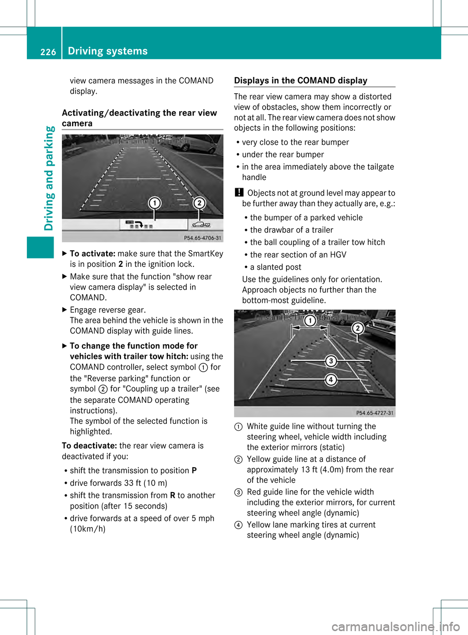
The area behind the vehicle is show ninthe
COMAND display with guide lines.
X To change the function mode for
vehicles with trailer tow hitch: using the
COMAND controller, select symbol 0002for
the "Reverse parking" function or
symbol 0003for "Coupling up a trailer" (see
the separate COMAND operating
instructions).
The symbol of the selected function is
highlighted.
To deactivate: the rear view camera is
deactivated if you:
R shift the transmission to position P
R drive forwards 33 ft (10 m)
R shift the transmission from Rto another
position (after 15 seconds)
R drive forwards at a speed of over 5mph
(10km/h) Displays in the COMAND display The rear view camera may show a distorted
view of obstacles, show them incorrectly or
not at all. The rear view camera does not show
objects in the following positions:
R
very close to the rear bumper
R under the rear bumper
R in the area immediately above the tailgate
handle
! Objects not at ground level may appear to
be further away than they actually are, e.g.:
R the bumper of a parked vehicle
R the drawbar of a trailer
R the ball coupling of a trailer tow hitch
R the rear section of an HGV
R a slanted post
Use the guidelines only for orientation.
Approach objects no further than the
bottom-most guideline. 0002
White guide line without turning the
steering wheel, vehicle width including
the exterior mirrors (static)
0003 Yellow guide line at a distance of
approximately 13 ft (4.0m) from the rear
of the vehicle
0021 Red guide line for the vehicle width
including the exterior mirrors, for current
steering wheel angle (dynamic)
0020 Yellow lane marking tires at current
steering wheel angle (dynamic) 226
Driving systemsDriving and parking
Page 233 of 454
Activation conditions
The 360° camera imag
ecan be displayed if:
R your vehicle is equipped with a 360°
camera
R COMAND is switched on, see the separate
COMAND operating instructions
R the 360° camera function is activated
Activating the 360° camera using the
SYS button X
Press and hold the 0003button for longer
than 2seconds, see the separate COMAND
operating instructions.
Depending on whether position Dor Ris
engaged, the following is shown:
R full screen display with the image from
the front camera
R full screen display with the image from
the rear camera
Activating the 360° camer awith
COMAND X
Press the 0003button, see the separate
COMAN Doperating instructions.
X Select System by turning
000E0002000Fthe
COMAND controller and press 000Cto
confirm.
X Select 360° camera and press
000Cto
confirm.
Depending on whether position Dor Ris
engaged, the following is shown:
R a split screen with top view and the
image from the front camera or
R a split screen with top view and the
image from the rear view camera
For further information about the COMAND
Controller, see the separate COMAND
operating instructions. Activating the 360° camer
ausing
reverse gear The 360° camera images can be
automatically displayed by engaging reverse
gear.
X
Make sure that the SmartKey is in position
2in the ignition lock.
X Make sure that the Activation by R gear setting is active in COMAND, see the
separate COMAND operating instructions.
X To show the 360° camer aimage: engage
reverse gear.
The COMAND display shows the area
behind the vehicle in spli tscreen:
R vehicle with guide lines
R top view of the vehicle
Selecting the split-screen and full
screen displays X
To switc hbetween spli tscreen views:
switch to the line with the vehicle icons by
sliding 000B0002the COMAND controller.
X Turn 000E0002000F the COMAND controller and
selec tone of the vehicle symbols.
X To switc hto full screen mode: select
Full screen by turning
000E0002000Fthe
COMAND controller and press 000Cto
confirm.
Displays in the COMAND display Important safety notes
!
Objects not at ground level may appear to
be further away than they actually are, e.g.:
R the bumper of a parked vehicle
R the drawbar of a trailer
R the ball coupling of a trailer tow hitch
R the rear section of an HGV
R a slanted post
Use the guidelines only for orientation.
Approach objects no further than the
bottom-mos tguideline. Driving systems
231Driving and parking Z
Page 237 of 454
ATTENTION ASSIST is reset when you
continue your journey and starts assessing
your tiredness agai nif:
R you switch off the engine.
R you take off you rseat belt and open the
driver's door, e.g. for a change of drivers or
to take a break. Night View Assist Plus
Important safety notes Night View Assist Plus is only an aid and is not
a substitute for attentive driving. Do not rely
on the Night View Assist Plus display. You are
responsible for the distance to the vehicle in
front, for vehicle speed and for braking in
good time. Drive carefully and always adapt
your driving style to suit the prevailing road
and traffic conditions.
The system may be impaired or may not
function if:
R there is poor visibility, e.g. due to snow,
rain, fog or spray
R the windshield is dirty, fogged up or
covered, for instance by a sticker, in the
vicinity of the camera
R on bends, on uphill gradient sordownhill
gradients
Pedestrian recognition may be impaired or
inoperative if:
R pedestrians are partially or entirely
obscured by objects, e.g. parked vehicles
R the silhouette of the pedestrian in the Night
View Assist Plus display is incomplete or
interrupted, e.g. by powerful light
reflections
R pedestrians do not contrast adequately
from the background
R pedestrians are not in an upright position,
e.g. sitting, squatting or lying General notes
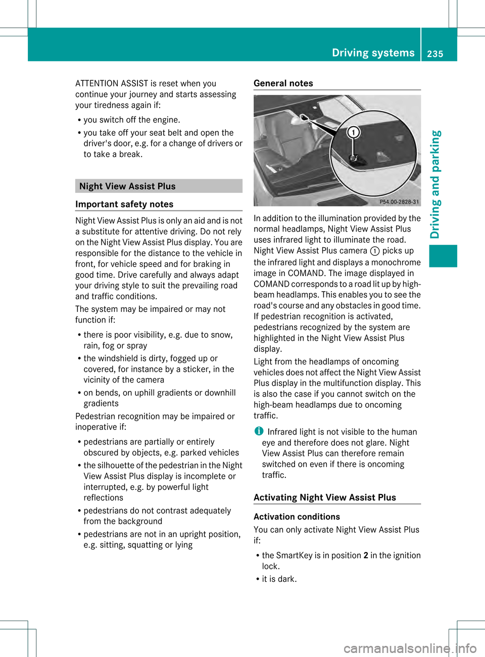
In addition to the illumination provided by the
normal headlamps, Night View Assist Plus
uses infrared light to illuminate the road.
Night View Assist Plus camera
0002picks up
the infrared light and displays a monochrome
image in COMAND. The image displayed in
COMAND corresponds to a road lit up by high-
beam headlamps. This enables you to see the
road's course and any obstacles in good time.
If pedestrian recognition is activated,
pedestrians recognized by the system are
highlighted in the Night View Assist Plus
display.
Light from the headlamps of oncoming
vehicles does not affect the Night View Assist
Plus display in the multifunction display .This
is also the case if you cannot switch on the
high-beam headlamps due to oncoming
traffic.
i Infrared light is not visible to the human
eye and therefore does not glare. Night
View Assist Plus can therefore remain
switched on even if there is oncoming
traffic.
Activating Night View Assist Plus Activation conditions
You can only activate Night View Assist Plus
if:
R
the SmartKey is in position 2in the ignition
lock.
R it is dark. Driving systems
235Driving and parking Z
Page 241 of 454
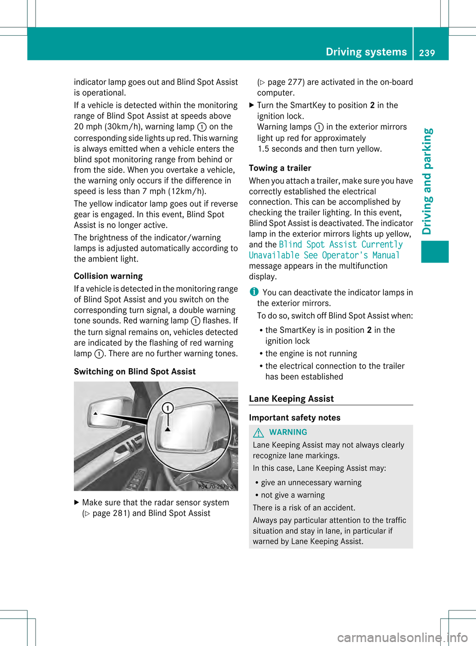
indicator lamp goes out and Blind Spot Assist
is operational.
If a vehicle is detected within the monitoring
range of Blind Spot Assist at speeds above
20 mph (30km/h), warning lamp 0002on the
corresponding side lights up red. This warning
is always emitted when a vehicle enters the
blind spot monitoring rang efrom behind or
from the side .When you overtake a vehicle,
the warning only occurs if the difference in
speed is less than 7mph (12km/h).
The yellow indicator lamp goes out if reverse
gear is engaged. In this event, Blind Spot
Assist is no longer active.
The brightness of the indicator/warning
lamps is adjusted automatically according to
the ambient light.
Collision warning
If a vehicle is detected in the monitoring range
of Blind Spot Assist and you switch on the
corresponding turn signal, a double warning
tone sounds. Red warning lamp 0002flashes. If
the turn signal remains on, vehicles detected
are indicated by the flashing of red warning
lamp 0002.There are no further warning tones.
Switching on Blind Spot Assist X
Make sure that the radar sensor system
(Y page 281) and Blind Spot Assist (Y
page 277) are activated in the on-board
computer.
X Turn the SmartKey to position 2in the
ignition lock.
Warning lamps 0002in the exterior mirrors
light up red for approximately
1.5 seconds and then turn yellow.
Towing atrailer
When you attach a trailer, make sure you have
correctly established the electrical
connection. This can be accomplished by
checking the trailer lighting. In this event,
Blind Spo tAssist is deactivated. The indicator
lamp in the exterior mirrors lights up yellow,
and the Blind Spot Assist Currently Unavailable See Operator's Manual
message appears in the multifunction
display.
i
You can deactivate the indicator lamps in
the exterior mirrors.
To do so, switch off Blind Spot Assist when:
R the SmartKey is in position 2in the
ignition lock
R the engine is not running
R the electrical connection to the trailer
has been established
Lane Keeping Assist Important safety notes
G
WARNING
Lane Keeping Assist may not always clearly
recognize lane markings.
In this case, Lane Keeping Assist may:
R give an unnecessary warning
R not give a warning
There is a risk of an accident.
Always pay particular attention to the traffic
situation and stay in lane, in particular if
warned by Lane Keeping Assist. Driving systems
239Driving and parking Z
Page 246 of 454
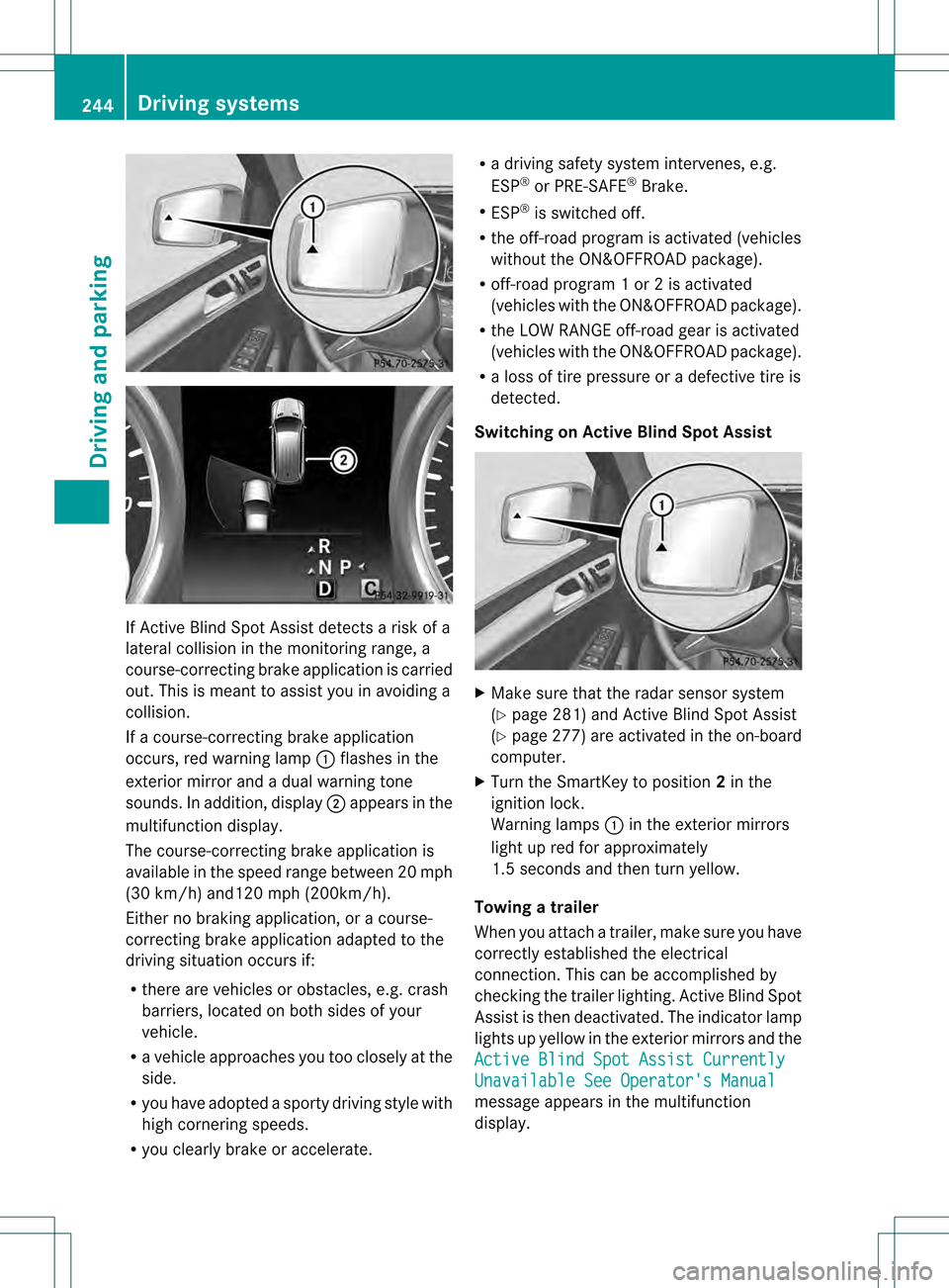
If Active Blind Spot Assist detects a risk of a
lateral collision in the monitoring range, a
course-correcting brake application is carried
out. This is meant to assist you in avoiding a
collision.
If a course-correcting brake application
occurs, red warning lamp 0002flashes in the
exterior mirror and a dual warning tone
sounds. In addition, display 0003appears in the
multifunction display.
The course-correcting brake application is
available in the speed range betwee n20m ph
(30 km/h) and120 mph (200km/h).
Either no braking application, or a course-
correcting brake application adapted to the
driving situation occurs if:
R there are vehicles or obstacles, e.g. crash
barriers, located on both sides of your
vehicle.
R a vehicle approaches you too closely at the
side.
R you have adopted a sporty driving style with
high cornering speeds.
R you clearly brake or accelerate. R
a driving safety system intervenes, e.g.
ESP ®
or PRE-SAFE ®
Brake.
R ESP ®
is switched off.
R the off-road program is activated (vehicles
without the ON&OFFROA Dpackage).
R off-road program 1 or 2 is activated
(vehicles with the ON&OFFROAD package).
R the LOW RANGE off-road gear is activated
(vehicles with the ON&OFFROAD package).
R a loss of tire pressure or a defective tire is
detected.
Switching on Active Blind Spot Assist X
Make sure that the radar sensor system
(Y page 281) and Active Blind Spot Assist
(Y page 277) are activated in the on-board
computer.
X Turn the SmartKey to position 2in the
ignition lock.
Warning lamps 0002in the exterior mirrors
light up red for approximately
1.5 seconds and then turn yellow.
Towing atrailer
When you attach a trailer, make sure you have
correctly established the electrical
connection. This can be accomplished by
checking the trailer lighting .Active Blind Spot
Assist is then deactivated. The indicator lamp
lights up yellow in the exterior mirrors and the
Active Blind Spot Assist Currently Unavailable See Operator's Manual
message appears in the multifunction
display. 244
Driving systemsDriving and parking
Page 250 of 454
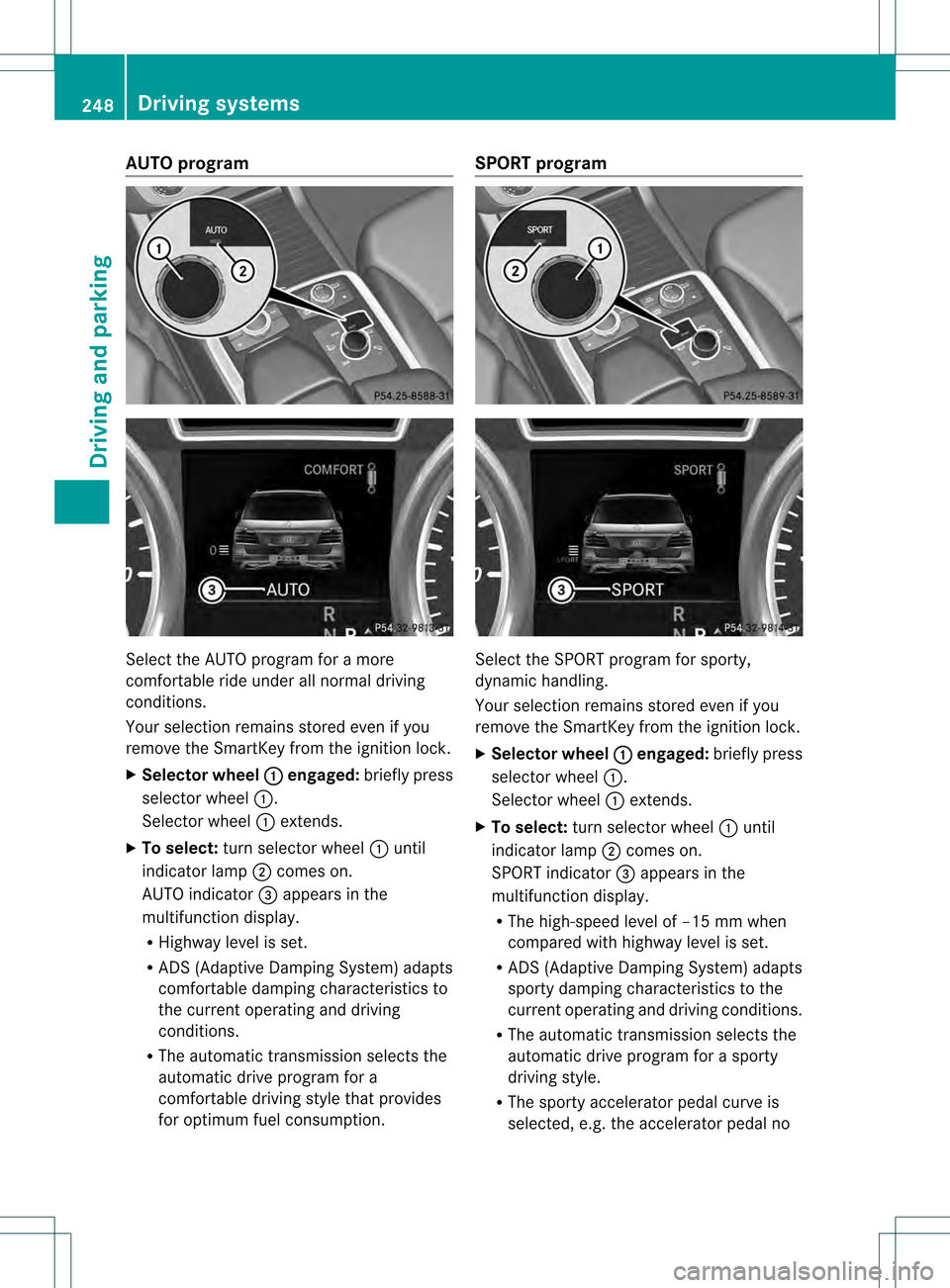
AUTO program
Select the AUTO program for a more
comfortable ride under all normal driving
conditions.
Your selection remains store
deven if you
remove the SmartKey from the ignition lock.
X Selector wheel 0002 engaged:
briefly press
selector wheel 0002.
Selector wheel 0002extends.
X To select: turn selector wheel 0002until
indicator lamp 0003comes on.
AUTO indicator 0021appears in the
multifunction display.
R Highway level is set.
R ADS (Adaptive Damping System) adapts
comfortable damping characteristics to
the current operating and driving
conditions.
R The automatic transmission selects the
automatic drive program for a
comfortable driving style that provides
for optimu mfuel consumption. SPORT program
Selec
tthe SPORT program for sporty,
dynamic handling.
Your selection remains stored even if you
remove the SmartKey from the ignition lock.
X Selector wheel 0002 engaged:
briefly press
selector wheel 0002.
Selector wheel 0002extends.
X To select: turn selector wheel 0002until
indicator lamp 0003comes on.
SPORT indicator 0021appears in the
multifunction display.
R The high-speed level of –15 mm when
compared with highway level is set.
R ADS (Adaptive Damping System) adapts
sporty damping characteristics to the
current operating and driving conditions.
R The automatic transmission selects the
automatic drive program for a sporty
driving style.
R The sporty accelerator pedal curve is
selected, e.g. the accelerator pedal no 248
Driving systemsDriving and parking
Page 258 of 454
Messages in the multifunction display
If a gearc
hange process has not been successful, the following messages may be displayed
in the multifunction display: Display messages Possible causes/consequences and
0001 Solutions
LOW RANGE Max.
Speed 40 km/h You have been driving faster than 40 km/h. Additionally, the
indicator lamp on the button in the center console blinks.
X
Drive more slowly to carry out the gear change process. LOW RANGE Shift to
Position N Briefly The transmission is in position
Dand you are driving at below
40 km/h.
X Shift the transmission to Nto complete the gear change
process. LOW RANGE Shifting
Canceled Please
Reactivate The gear change process was not carried out.
X
Ensure that all gear change conditions are fulfilled and carry out
the gear change process again. LOW RANGE Stop
Apply Parking Brake Aw
arning tone also sounds. The gear change proces shas no tbeen
completed. LOW RANGE is in the neutral position .There is no
connection between the engine and the drive wheels.
! Do not drive any further. You could otherwise damage the
vehicle's drive train.
X Stop the vehicle. Take into account the road and traffic
conditions when doing this.
X Depress the electric parking brake (Y page 184).
X Carry out the gear change process again.
If the gear change process has been carried out, the LOW RANGE
Stop Apply Parking Brake message disappears.
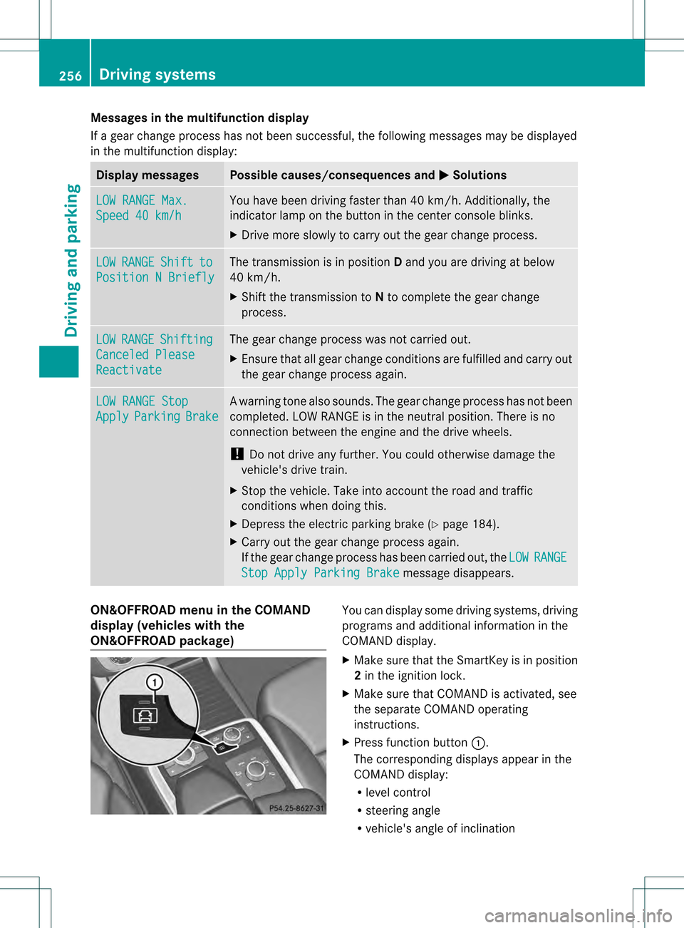
ON&OFFROAD menu in the COMAND
display (vehicles with the
ON&OFFROAD package) You can display some driving systems, driving
programs and additional information in the
COMAND display.
X Make sure that the SmartKey is in position
2in the ignition lock.
X Make sure that COMAND is activated, see
the separate COMAND operating
instructions.
X Press function button 0002.
The corresponding displays appearint he
COMAND display:
R level control
R steering angle
R vehicle's angle of inclination 256
Driving systemsDriving and parking
Page 262 of 454

Ball coupling recess
Holes in the ball coupling and ball coupling recess
X
Insert the ball coupling horizontally into ball
coupling recess 0003in the direction of the
arrow until the holes in ball coupling 0021are
in line with the holes in ball coupling
recess 0020. Bolt
X
Slide bolt 001Einto the hole in the ball
coupling recess and the ball coupling to the
stop. Bolt and spring cotter
X
Secure the bol tusing spring cotter 001F. Correctly installed and secured ball coupling
X
Check the ball coupling, bolt and spring
cotter for correct installation.
If the ball coupling cannot be correctly
mounted, remove the ball coupling. Under
these circumstances, the ball coupling must
not be used for trailer towing.
If the ball coupling cannot be locked and the
key cannot be removed, remove the ball
coupling and clean it. If the ball coupling can
still not be installed (locked) after it has been
cleaned, remove the ball coupling. The trailer
tow hitch must then not be used to tow a
trailer, as safe operation cannot be
guaranteed.
Have the entire trailer tow hitch checked at a
qualified specialist workshop. Coupling up a trailer
! Do not connect the trailer's brake system
(if featured) to the hydraulic brake system 260
Towing
atrailerDriving an d parking
Page 270 of 454
vehicle and do not stand near the vehicle until
the engine has cooled down.
! Adisplay message is shown if the coolant
temperature is too high.
If the coolant temperature is over
248 ‡(120 †), do not continue driving. The
engine will otherwise be damaged.
The coolan ttemperature gauge is in the
instrument cluster on the right-hand side
(Y page 33).
Under normal operating conditions and with
the specified coolant level, the coolant
temperature may rise to 248 ‡ (120 †). Tachometer
! Do not drive in the overrevving range, as
this could damage the engine.
The red band in the tachometer indicates the
engine's overrevving range.
The fuel supply is interrupted to protec tthe
engine when the red band is reached. Outside temperature display
You should pay special attention to road
conditions when temperatures are around
freezing point.
The outside temperature display is in the
multifunction display (Y page 269).
Changes in the outside temperature are
displayed after a short delay. Speedometer with segments
The segments in the speedometer indicate
which speed range is available.
R Cruise control activated (Y page 195):
The segments light up from the stored
speed to the maximum speed.
R DISTRONIC PLUS activated (Y page 198):One or two segments in the set speed
range light up.
R DISTRONIC PLUS detectsav ehicle in front:
The segments between the speed of the
vehicle in fron tand the stored speed light
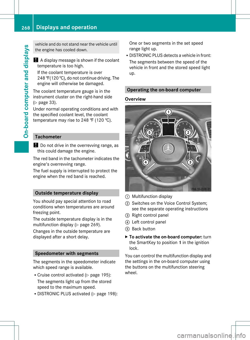
up. Operating the on-board computer
Overview 0002
Multifunctio ndisplay
0003 Switches on the Voice Control System;
see the separate operating instructions
0021 Right control panel
0020 Left control panel
001E Back button
X To activat ethe on-board computer: turn
the SmartKey to position 1in the ignition
lock.
You can control the multifunction display and
the settings in the on-board computer using
the buttons on the multifunction steering
wheel. 268
Displays and operationOn-board computer and displays