MERCEDES-BENZ M-Class 2014 W166 Owner's Manual
Manufacturer: MERCEDES-BENZ, Model Year: 2014, Model line: M-Class, Model: MERCEDES-BENZ M-Class 2014 W166Pages: 462, PDF Size: 6.23 MB
Page 261 of 462
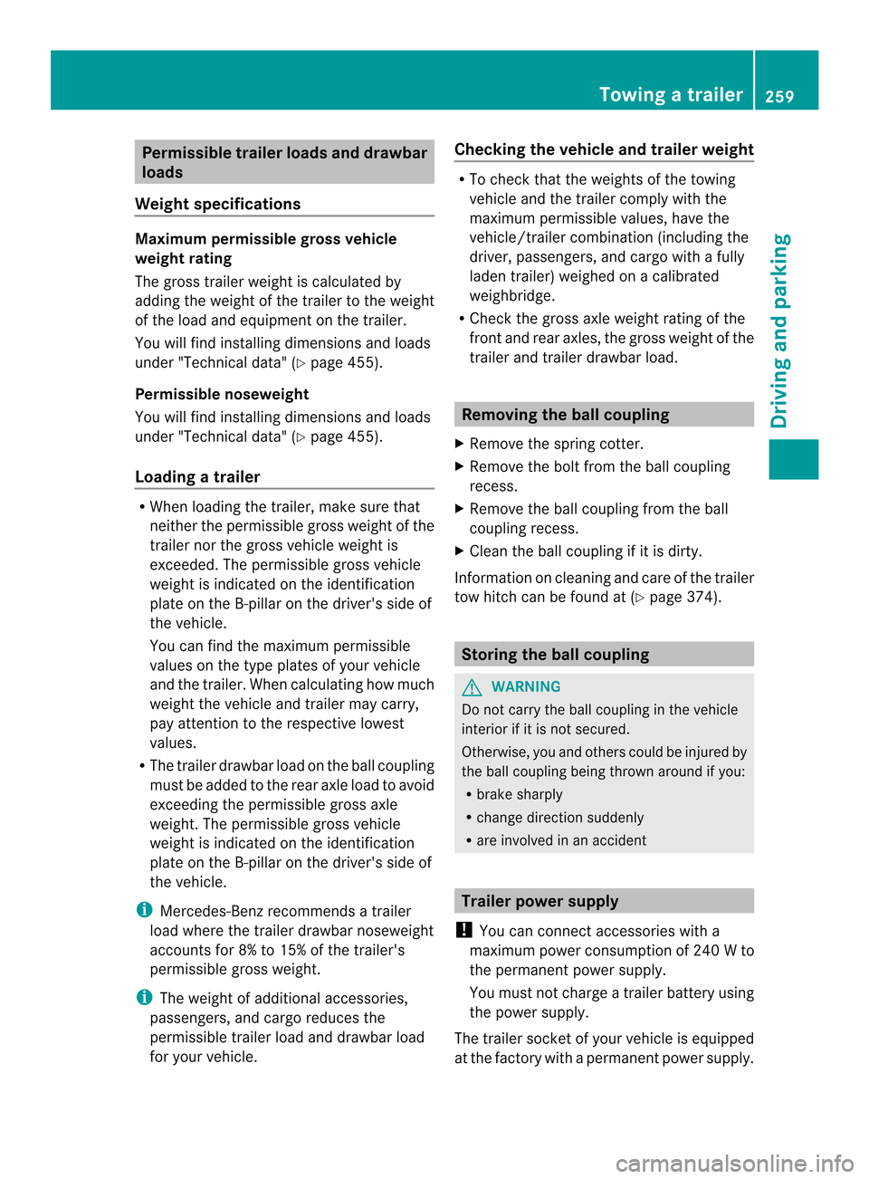
Permissible trailer loads and drawbar
loads
Weight specifications Maximump
ermissible gross vehicle
weight rating
The gross trailer weight is calculated by
adding the weight of the trailer to the weight
of the load and equipment on the trailer.
You will find installing dimensions and loads
under "Technical data" ( Ypage 455).
Permissible noseweight
You will find installing dimensions and loads
under "Technical data" ( Ypage 455).
Loading atrailer R
When loading the trailer, make sure that
neithe rthe permissible gross weight of the
trailer nor the gross vehicle weight is
exceeded. The permissible gross vehicle
weight is indicated on the identification
plate on the B-pillar on the driver's side of
the vehicle.
You can find the maximum permissible
values on the type plates of your vehicle
and the trailer. When calculating how much
weight the vehicle and trailer may carry,
pay attention to the respective lowest
values.
R The trailer drawbarl oad on the ball coupling
must be added to the rear axle load to avoid
exceeding the permissible gross axle
weight. The permissible gross vehicle
weight is indicated on the identification
plate on the B-pillar on the driver's side of
the vehicle.
i Mercedes-Benz recommends atrailer
load where the trailer drawbar noseweight
accounts for 8% to 15% of the trailer's
permissible gross weight.
i The weight of additional accessories,
passengers, and cargo reduces the
permissible trailer load and drawbar load
for yourv ehicle. Checking the vehicle and trailer weight R
To chec kthat the weights of the towing
vehicle and the trailer comply with the
maximum permissible values, have the
vehicle/trailer combination (including the
driver, passengers, and cargo with a fully
laden trailer) weighed on a calibrated
weighbridge.
R Check the gross axle weight rating of the
front and rear axles, the gross weight of the
trailer and trailer drawbarl oad. Removing the ball coupling
X Remove the spring cotter.
X Remove the bolt from the ball coupling
recess.
X Remove the ball coupling from the ball
coupling recess.
X Clean the ball coupling if it is dirty.
Information on cleaning and care of the trailer
tow hitch can be found at (Y page 374). Storing the ball coupling
G
WARNING
Do not carry the ball coupling in the vehicle
interior if it is not secured.
Otherwise, you and others could be injured by
the ball coupling being thrown around if you:
R brake sharply
R change direction suddenly
R are involved in an accident Trailer power supply
! You can connect accessories with a
maximum power consumption of 240 Wto
the permanent powe rsupply.
You must no tcharge a trailer battery using
the power supply.
The trailer socket of your vehicle is equipped
at the factory with apermanen tpower supply. Towing
atrailer
259Driving an d parking Z
Page 262 of 462
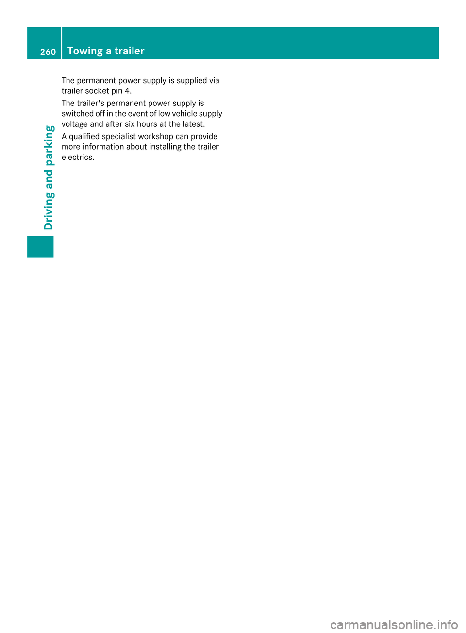
The permanen
tpower supply is supplied via
trailer socket pin 4.
The trailer's permanent power supply is
switched off in the event of low vehicle supply
voltage and after six hours at the latest.
Aq ualified specialist workshop can provide
more information about installing the trailer
electrics. 260
Towing
atrailerDriving an d parking
Page 263 of 462
Useful information
............................262
Important safety notes ....................262
Displays and operation ....................263
Menus and submenus ......................266
Display messages ............................. 282
Warning and indicator lamps in the
instrument cluster ............................316 261On-board computer and displays
Page 264 of 462
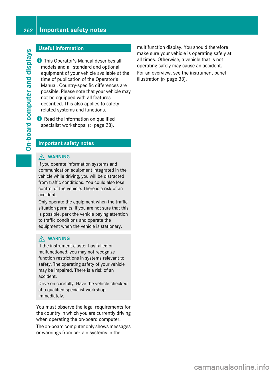
Useful information
i This Operator's Manual describes all
models and all standard and optional
equipment of your vehicle available at the
time of publication of the Operator's
Manual. Country-specific differences are
possible. Please note that your vehicle may
not be equipped with all features
described. This also applies to safety-
related systems and functions.
i Read the information on qualified
specialist workshops: (Y page 28).Important safety notes
G
WARNING
If you operate information systems and
communication equipment integrated in the
vehicle while driving, you will be distracted
from traffic conditions. You could also lose
control of the vehicle. There is a risk of an
accident.
Only operate the equipment when the traffic
situatio npermits .Ifyou are not sure that this
is possible, park the vehicle paying attention
to traffic conditions and operate the
equipment when the vehicle is stationary. G
WARNING
If the instrument cluster has failed or
malfunctioned, you may not recognize
function restrictions in systems relevant to
safety. The operating safety of your vehicle
may be impaired. There is a risk of an
accident.
Drive on carefully. Have the vehicle checked
at a qualified specialist workshop
immediately.
You must observe the legal requirements for
the country in which you are currently driving
when operating the on-board computer.
The on-board computer only shows messages
or warnings from certain systems in the multifunction display
.You should therefore
make sure your vehicle is operating safely at
all times. Otherwise, a vehicle that is not
operating safely may cause an accident.
For an overview, see the instrument panel
illustration (Y page 33).262
Important safety notesOn-board computer and displays
Page 265 of 462
Displays and operation
Instrument cluster
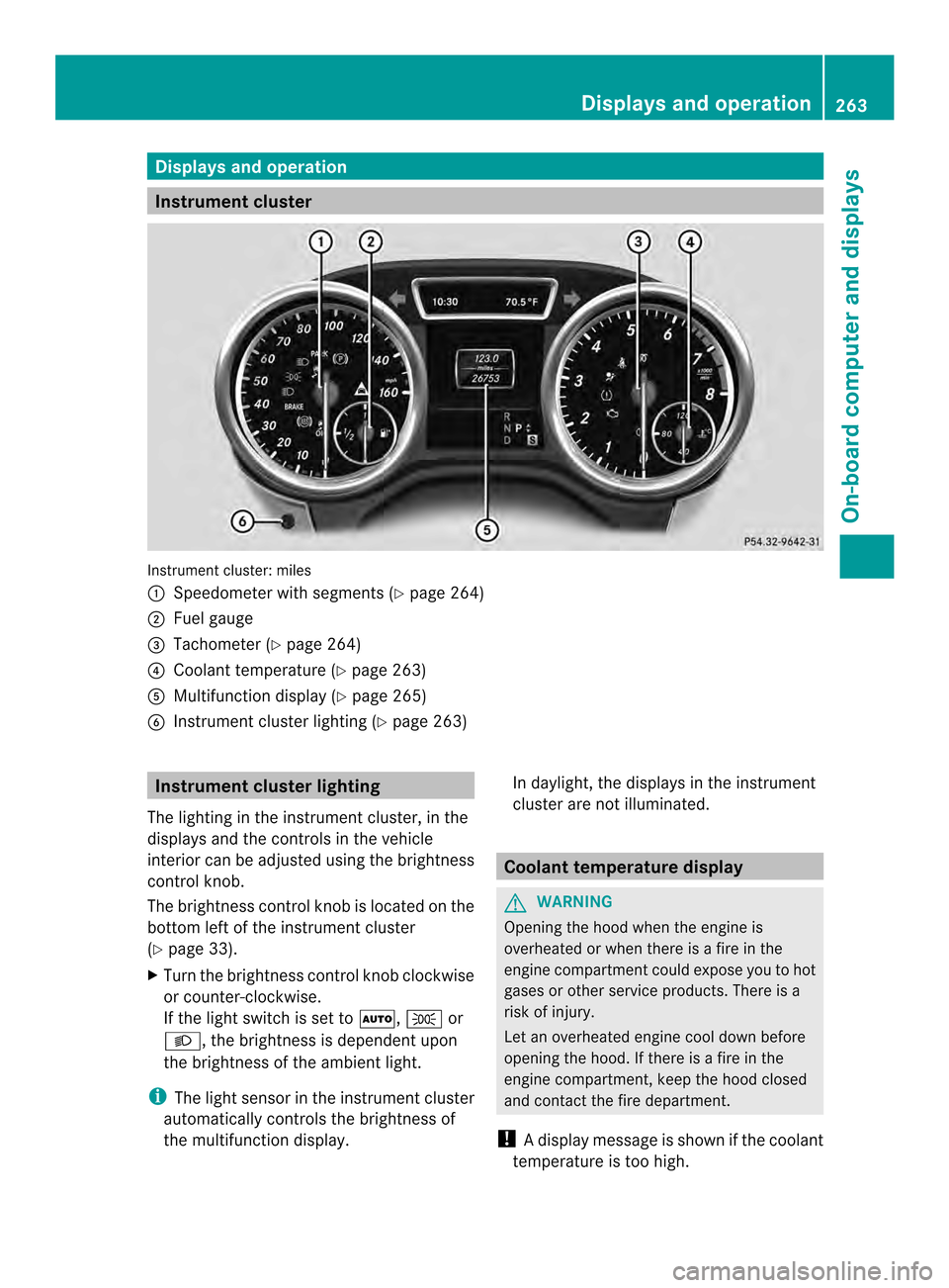
Instrument cluster: miles
0002
Speedometer with segments (Y page 264)
0003 Fuel gauge
0023 Tachometer (Y page 264)
0022 Coolant temperature ( Ypage 263)
0020 Multifunction display (Y page 265)
0021 Instrumen tcluster lighting (Y page 263) Instrument cluster lighting
The lighting in the instrumen tcluster, in the
displays and the controls in the vehicle
interior can be adjusted using the brightness
control knob.
The brightness control knob is located on the
bottom left of the instrument cluster
(Y page 33).
X Turn the brightness control knob clockwise
or counter-clockwise.
If the light switch is set to 0006,0016or
000D, the brightness is dependent upon
the brightness of the ambien tlight.
i The light sensor in the instrumen tcluster
automatically controls the brightness of
the multifunction display. In daylight, the displays in the instrument
cluster are not illuminated. Coolant temperature display
G
WARNING
Opening the hood when the engine is
overheated or when there is a fire in the
engine compartmen tcould expose you to hot
gases or other service products. There is a
risk of injury.
Let an overheated engine cool down before
opening the hood. If there is a fire in the
engine compartment, keep the hood closed
and contact the fire department.
! Adisplay message is shown if the coolant
temperature is too high. Displays and operation
263On-board computer and displays Z
Page 266 of 462
If the coolant temperature is over
248 ‡(120 †), do not continue driving. The
engine will otherwise be damaged.
The coolant temperature gauge is in the
instrument cluster on the right-hand side
(Y page 33).
Under normal operating conditions and with
the specified coolant level, the coolant
temperature may rise to 248 ‡ (120 †). Tachometer
! Do not drive in the overrevving range, as
this could damage the engine.
The red band in the tachometer indicates the
engine's overrevving range.
The fuel supply is interrupted to protect the
engine when the red band is reached. Outside temperature display
You should pay special attention to road
conditions when temperatures are around
freezing point.
The outside temperature display is in the
multifunction display (Y page 265).
Changes in the outside temperature are
displayed after a short delay. Speedometer with segments
The segments in the speedometer indicate
which speed range is available.
R Cruise control activated (Y page 191):
The segments lightu p from the stored
speed to the maximum speed.
R DISTRONIC PLUS activated (Y page 194):
One or two segments in the set speed
range light up.
R DISTRONIC PLUS detects avehicle in front:
The segments between the speed of the
vehicle in fron tand the stored speed light
up. Operating the on-board computer
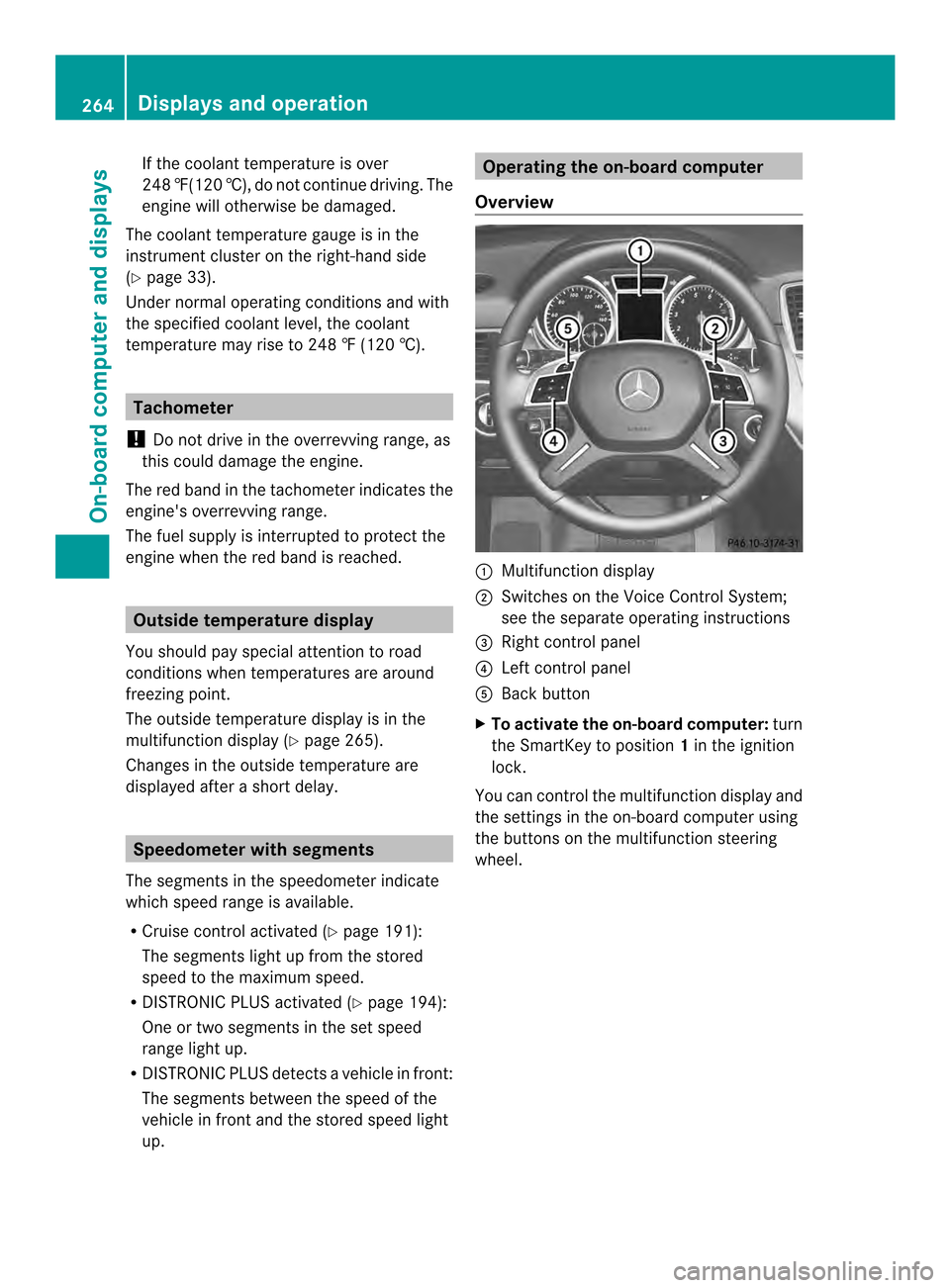
Overview 0002
Multifunctio ndisplay
0003 Switches on the Voice Control System;
see the separate operating instructions
0023 Right control panel
0022 Left control panel
0020 Back button
X To activat ethe on-board computer: turn
the SmartKey to position 1in the ignition
lock.
You can control the multifunction display and
the settings in the on-board computer using
the buttons on the multifunction steering
wheel. 264
Displays and operationOn-board computer and displays
Page 267 of 462
Left control panel
0002
0005 R
Calls up the menu and menu bar 0003
0004
Press briefly:
R
Scrolls in lists
R Selects a submenu or function
R In the Audio menu: selects a
stored station, an audio track or
a video scene
R In the Tel (telephone) menu:
switches to the phone book and
selects a name or telephone
number 0003
0004
Press and hold:
R
In the Audio menu: selects the
previous/nex tstation or selects
an audio track or a video scene
using rapid scrolling
R In the Tel (Telephone) menu:
starts rapid scrolling if the phone
book is open 000B R
Confirms a selection/display
message
R In the Tel (telephone) menu:
switches to the telephone book
and starts dialing the selected
number
R In the Audio menu: stops the
station search function at the
desired station Right control panel
000D R
Rejects or ends a call
R Exits phone book/redial
memory 0004 R
Makes or accepts a call
R Switches to the redial memory 0009
000A R
Adjusts the volume 0006 R
Mute Back button
0007
Press briefly:
R Back
R Switches off the Voice Control
System; see the separate
operating instructions
R Hides display messages/calls
up the last Trip menu function
used
R Exits the telephone book/redial
memory 0007
Press and hold:
R Calls up the standard display in
the Trip menu
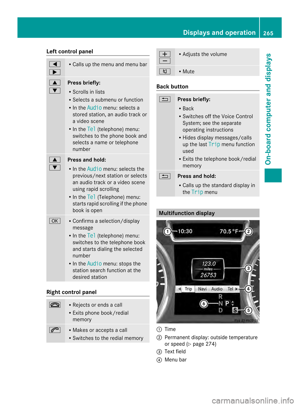
Multifunction display
0002
Time
0003 Permanent display: outside temperature
or speed (Y page 274)
0023 Text field
0022 Menu bar Displays and operation
265On-boardcompu ter and displays Z
Page 268 of 462
0020
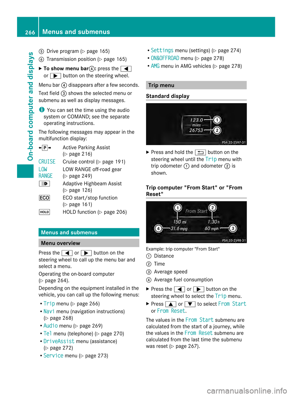
Drive program (Y page 165)
0021 Transmission positio n(Ypage 165)
X To show menu bar 0022:press the 0002
or 0005 button on the steering wheel.
Menu bar 0022disappears after a few seconds.
Text field 0023shows the selected menu or
submenu as well as display messages.
i You can set the time using the audio
system or COMAND; see the separate
operating instructions.
The following messages may appear in the
multifunction display:
00090012000A Active Parking Assist
(Ypage 216)
CRUISE Cruise control (Y
page 191)
LOW RANGE LOW RANGE off-road gear
(Y
page 249)
0005 Adaptive Highbeam Assist
(Ypage 126)
0012 ECO start/stop function
(Ypage 161)
0001 HOLD function (Y page 206)Menus and submenus
Menu overview
Press the 0002or0005 button on the
steering wheel to call up the menu bar and
select a menu.
Operating the on-board computer
(Y page 264).
Depending on the equipment installed in the
vehicle, you can call up the following menus:
R Trip menu (Y
page 266)
R Navi menu (navigation instructions)
(Y page 268)
R Audio menu (Y
page 269)
R Tel menu (telephone) (Y
page 270)
R DriveAssist menu (assistance)
(Y page 272)
R Service menu (Y
page 273) R
Settings menu (settings) (Y
page 274)
R ON&OFFROAD menu (Y
page 278)
R AMG menu in AMG vehicles (Y
page 278) Trip menu
Standard display X
Press and hold the 0007button on the
steering wheel until the Trip menu with
trip odometer 0002and odometer 0003is
shown.
Trip computer "From Start" or "From
Reset" Example: trip computer "From Start"
0002
Distance
0003 Time
0023 Average speed
0022 Average fuel consumption
X Press the 0002or0005 button on the
steering wheel to select the Trip menu.
X Press 0003or0004 to select From Start or
From Reset .
The values in the From Start submenu are
calculated from the start of a journey, while
the values in the From Reset submenu are
calculated from the last time the submenu
was reset (Y page 267).266
Menus and submenusOn-board computer and displays
Page 269 of 462
The
From Start trip computer is
automatically reset when:
R the ignition has been switched off for more
than four hours.
R 999 hours have been exceeded.
R 9,999 miles have been exceeded.
The From Reset trip computer is
automatically reset if the value exceeds
9,999 hours or 99,999 miles.
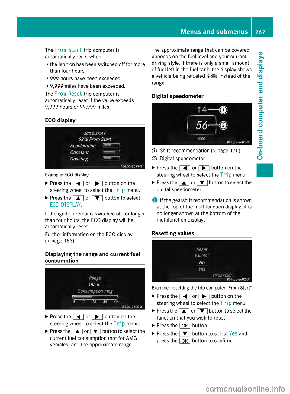
ECO display Example: ECO display
X
Press the 0002or0005 button on the
steering wheel to select the Trip menu.
X Press the 0003or0004 button to select
ECO DISPLAY .
If the ignition remains switched off for longer
than four hours, the ECO display will be
automatically reset.
Further information on the ECO display
(Y page 183).
Displaying the range and current fuel
consumption X
Press the 0002or0005 button on the
steering wheel to select the Trip menu.
X Press the 0003or0004 button to select the
current fuel consumption (not for AMG
vehicles) and the approximate range. The approximate range that can be covered
depends on the fuel level and your current
driving style. If there is only a small amount
of fuel left in the fuel tank, the display shows
a vehicle being refueled
000Ainstead of the
range.
Digital speedometer 0002
Shift recommendation (Y page 170)
0003 Digital speedometer
X Press the 0002or0005 button on the
steering wheel to select the Trip menu.
X Press the 0003or0004 button to select the
digital speedometer.
i If the gearshift recommendation is shown
at the top of the multifunction display, it is
no longer shown at the bottom of the
multifunction display.
Resetting values Example: resetting the trip computer "From Start"
X
Press the 0002or0005 button on the
steering wheel to select the Trip menu.
X Press the 0003or0004 button to select the
function that you wish to reset.
X Press the 000Bbutton.
X Press the 0004button to select Yes and
press the 000Bbutton to confirm. Menus and submenus
267On-board computer and displays Z
Page 270 of 462
You can reset the values of the following
functions:
R
Trip odometer
R "From Start" trip computer
R "From Reset" trip computer
R ECO display
i When you reset the values in the "ECO
display", the values in the trip computer
"From Start" are likewise reset .When you
reset the values in the trip computer "From
Start", the values in the "ECO display"are
likewise reset. Navigation system menu
Displaying navigation instructions In the
Navi menu, the multifunction display
shows navigation instructions.
For more information, see the separate
operating instructions.
X Switch on the audio system with Becker ®
MAP PILOT or COMAND; see the separate
operating instructions.
X Press the 0002or0005 button on the
steering wheel to select the Navi menu.
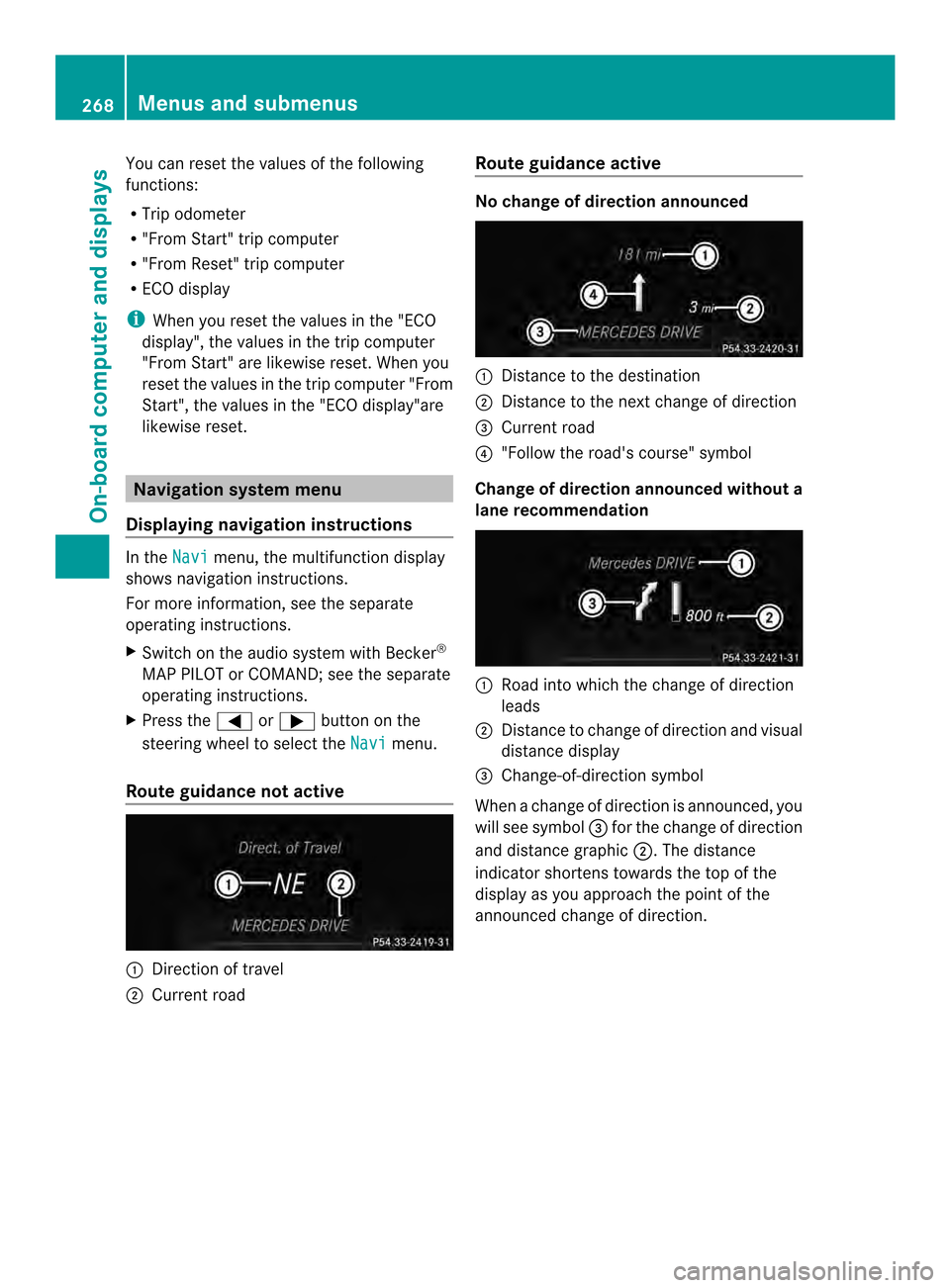
Route guidance not active 0002
Direction of travel
0003 Current road Route guidance active No change of direction announced
0002
Distance to the destination
0003 Distance to the next change of direction
0023 Current road
0022 "Follow the road's course" symbol
Change of direction announced without a
lane recommendation 0002
Road into which the change of direction
leads
0003 Distance to change of direction and visual
distance display
0023 Change-of-direction symbol
When a change of direction is announced, you
will see symbol 0023for the change of direction
and distance graphic 0003.The distance
indicator shortens towards the top of the
display as you approach the point of the
announced change of direction. 268
Menus and submenusOn-board computer and displays