page 98 MERCEDES-BENZ R-Class 2012 W251 Owner's Manual
[x] Cancel search | Manufacturer: MERCEDES-BENZ, Model Year: 2012, Model line: R-Class, Model: MERCEDES-BENZ R-Class 2012 W251Pages: 368, PDF Size: 15.19 MB
Page 259 of 368
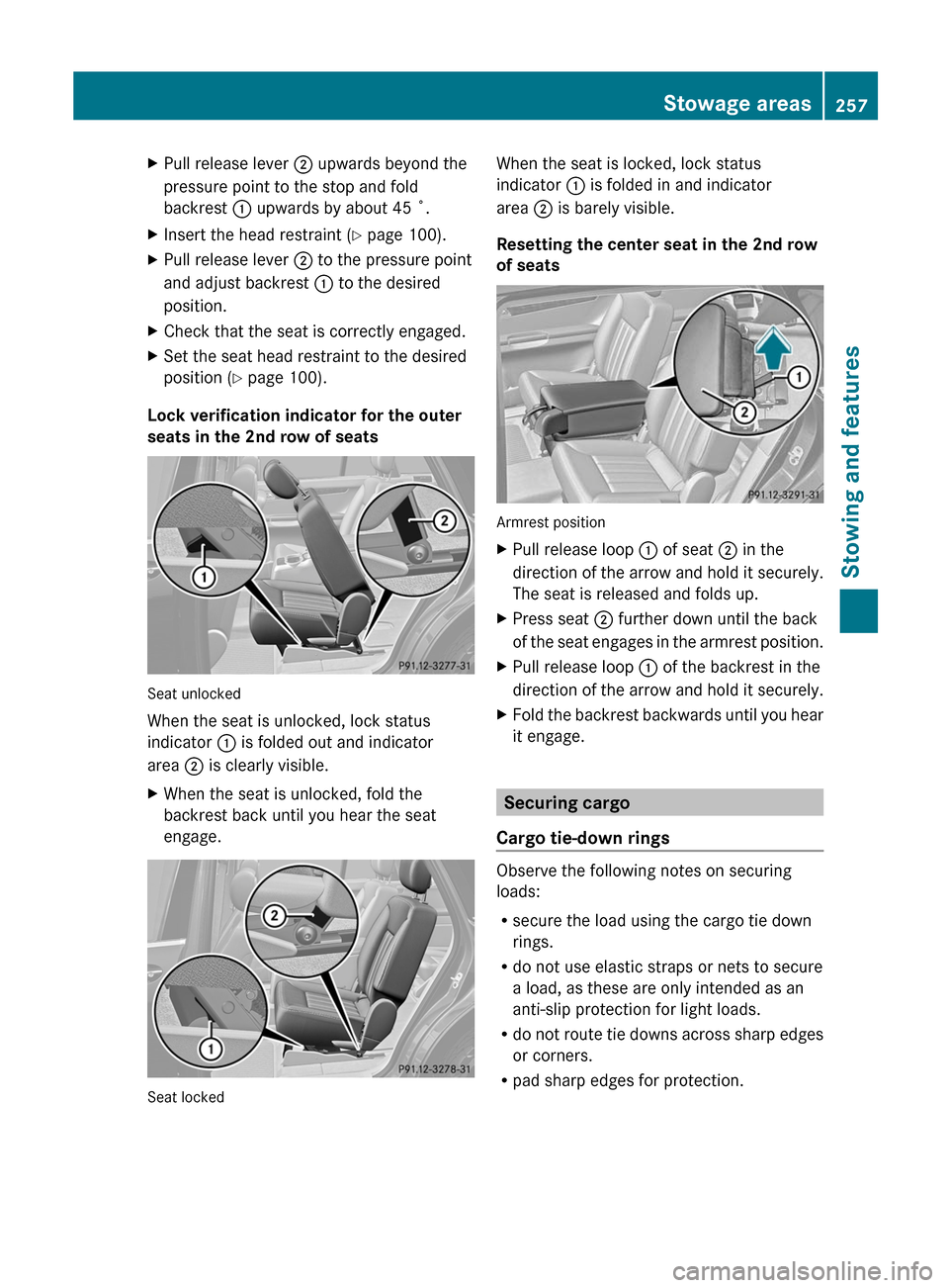
XPull release lever ; upwards beyond the
pressure point to the stop and fold
backrest : upwards by about 45 ˚.XInsert the head restraint ( Y page 100).XPull release lever ; to the pressure point
and adjust backrest : to the desired
position.XCheck that the seat is correctly engaged.XSet the seat head restraint to the desired
position ( Y page 100).
Lock verification indicator for the outer
seats in the 2nd row of seats
Seat unlocked
When the seat is unlocked, lock status
indicator : is folded out and indicator
area ; is clearly visible.
XWhen the seat is unlocked, fold the
backrest back until you hear the seat
engage.
Seat locked
When the seat is locked, lock status
indicator : is folded in and indicator
area ; is barely visible.
Resetting the center seat in the 2nd row
of seats
Armrest position
XPull release loop : of seat ; in the
direction of the arrow and hold it securely.
The seat is released and folds up.XPress seat ; further down until the back
of the seat engages in the armrest position.XPull release loop : of the backrest in the
direction of the arrow and hold it securely.XFold the backrest backwards until you hear
it engage.
Securing cargo
Cargo tie-down rings
Observe the following notes on securing
loads:
R secure the load using the cargo tie down
rings.
R do not use elastic straps or nets to secure
a load, as these are only intended as an
anti-slip protection for light loads.
R do not route tie downs across sharp edges
or corners.
R pad sharp edges for protection.
Stowage areas257Stowing and featuresZ
Page 261 of 368
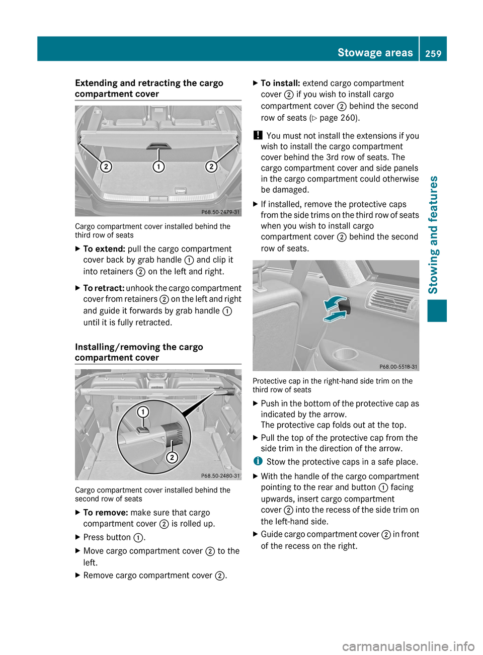
Extending and retracting the cargo
compartment cover
Cargo compartment cover installed behind the
third row of seats
XTo extend: pull the cargo compartment
cover back by grab handle : and clip it
into retainers ; on the left and right.XTo retract: unhook the cargo compartment
cover from retainers ; on the left and right
and guide it forwards by grab handle :
until it is fully retracted.
Installing/removing the cargo
compartment cover
Cargo compartment cover installed behind the
second row of seats
XTo remove: make sure that cargo
compartment cover ; is rolled up.XPress button :.XMove cargo compartment cover ; to the
left.XRemove cargo compartment cover ;.XTo install: extend cargo compartment
cover ; if you wish to install cargo
compartment cover ; behind the second
row of seats ( Y page 260).
!
You must not install the extensions if you
wish to install the cargo compartment
cover behind the 3rd row of seats. The
cargo compartment cover and side panels
in the cargo compartment could otherwise
be damaged.
XIf installed, remove the protective caps
from the side trims on the third row of seats
when you wish to install cargo
compartment cover ; behind the second
row of seats.
Protective cap in the right-hand side trim on the
third row of seats
XPush in the bottom of the protective cap as
indicated by the arrow.
The protective cap folds out at the top.XPull the top of the protective cap from the
side trim in the direction of the arrow.
i Stow the protective caps in a safe place.
XWith the handle of the cargo compartment
pointing to the rear and button : facing
upwards, insert cargo compartment
cover ; into the recess of the side trim on
the left-hand side.XGuide cargo compartment cover ; in front
of the recess on the right.Stowage areas259Stowing and featuresZ
Page 263 of 368
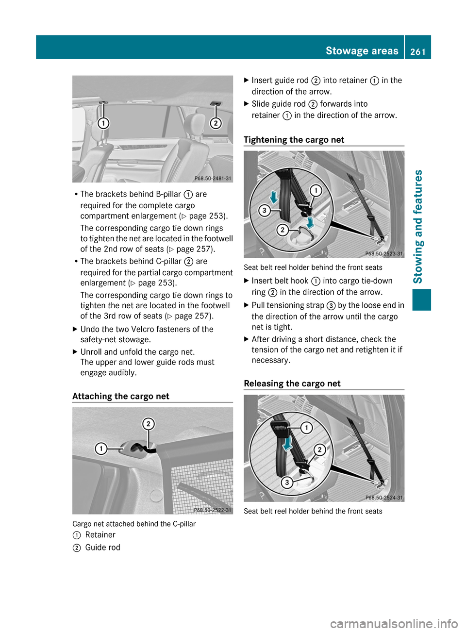
RThe brackets behind B-pillar : are
required for the complete cargo
compartment enlargement ( Y page 253).
The corresponding cargo tie down rings
to tighten the net are located in the footwell
of the 2nd row of seats ( Y page 257).
R The brackets behind C-pillar ; are
required for the partial cargo compartment
enlargement ( Y page 253).
The corresponding cargo tie down rings to
tighten the net are located in the footwell
of the 3rd row of seats ( Y page 257).
XUndo the two Velcro fasteners of the
safety-net stowage.XUnroll and unfold the cargo net.
The upper and lower guide rods must
engage audibly.
Attaching the cargo net
Cargo net attached behind the C-pillar
:Retainer;Guide rodXInsert guide rod ; into retainer : in the
direction of the arrow.XSlide guide rod ; forwards into
retainer : in the direction of the arrow.
Tightening the cargo net
Seat belt reel holder behind the front seats
XInsert belt hook : into cargo tie-down
ring ; in the direction of the arrow.XPull tensioning strap = by the loose end in
the direction of the arrow until the cargo
net is tight.XAfter driving a short distance, check the
tension of the cargo net and retighten it if
necessary.
Releasing the cargo net
Seat belt reel holder behind the front seats
Stowage areas261Stowing and featuresZ
Page 264 of 368
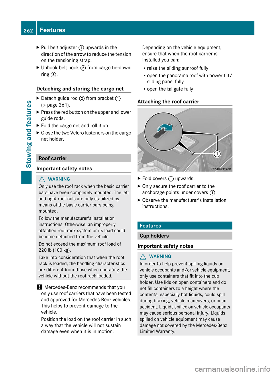
XPull belt adjuster : upwards in the
direction of the arrow to reduce the tension
on the tensioning strap.XUnhook belt hook ; from cargo tie-down
ring =.
Detaching and storing the cargo net
XDetach guide rod ; from bracket :
( Y page 261).XPress the red button on the upper and lower
guide rods.XFold the cargo net and roll it up.XClose the two Velcro fasteners on the cargo
net holder.
Roof carrier
Important safety notes
GWARNING
Only use the roof rack when the basic carrier
bars have been completely mounted. The left
and right roof rails are only stabilized by
means of the basic carrier bars being
mounted.
Follow the manufacturer's installation
instructions. Otherwise, an improperly
attached roof rack system or its load could
become detached from the vehicle.
Do not exceed the maximum roof load of
220 lb (100 kg).
Take into consideration that when the roof
rack is loaded, the handling characteristics
are different from those when operating the
vehicle without the roof rack loaded.
! Mercedes-Benz recommends that you
only use roof carriers that have been tested
and approved for Mercedes-Benz vehicles.
This helps to prevent damage to the
vehicle.
Position the load on the roof carrier in such
a way that the vehicle will not sustain
damage even when it is in motion.
Depending on the vehicle equipment,
ensure that when the roof carrier is
installed you can:
R raise the sliding sunroof fully
R open the panorama roof with power tilt/
sliding panel fully
R open the tailgate fully
Attaching the roof carrierXFold covers : upwards.XOnly secure the roof carrier to the
anchorage points under covers :.XObserve the manufacturer's installation
instructions.
Features
Cup holders
Important safety notes
GWARNING
In order to help prevent spilling liquids on
vehicle occupants and/or vehicle equipment,
only use containers that fit into the cup
holder. Use lids on open containers and do
not fill containers to a height where the
contents, especially hot liquids, could spill
during braking, vehicle maneuvers, or in an
accident. Liquids spilled on vehicle occupants
may cause serious personal injury. Liquids
spilled on vehicle equipment may cause
damage not covered by the Mercedes-Benz
Limited Warranty.
262FeaturesStowing and features
Page 268 of 368
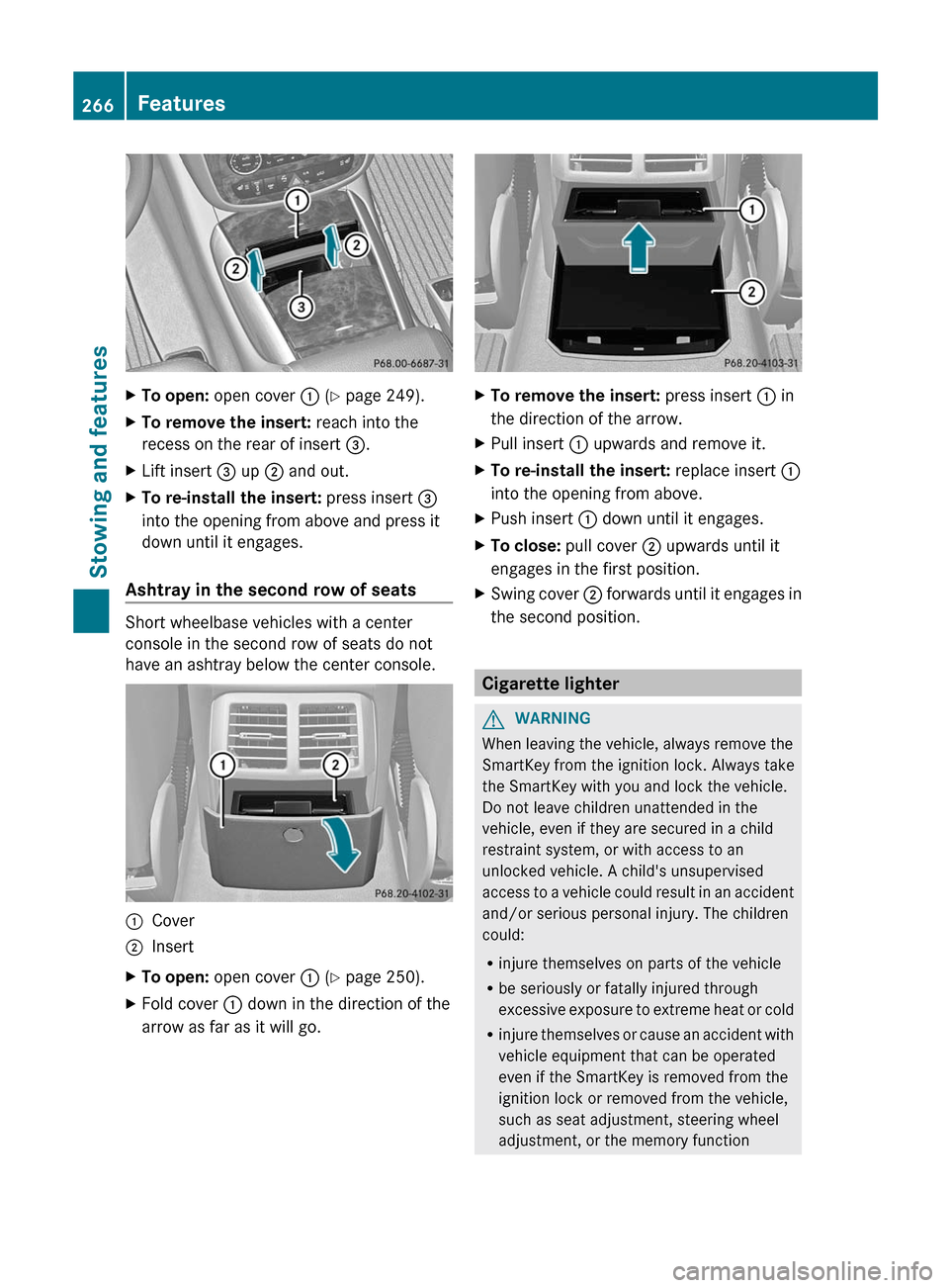
XTo open: open cover : (Y page 249).XTo remove the insert: reach into the
recess on the rear of insert =.XLift insert = up ; and out.XTo re-install the insert: press insert =
into the opening from above and press it
down until it engages.
Ashtray in the second row of seats
Short wheelbase vehicles with a center
console in the second row of seats do not
have an ashtray below the center console.
:Cover;InsertXTo open: open cover : (Y page 250).XFold cover : down in the direction of the
arrow as far as it will go.XTo remove the insert: press insert : in
the direction of the arrow.XPull insert : upwards and remove it.XTo re-install the insert: replace insert :
into the opening from above.XPush insert : down until it engages.XTo close: pull cover ; upwards until it
engages in the first position.XSwing cover ; forwards until it engages in
the second position.
Cigarette lighter
GWARNING
When leaving the vehicle, always remove the
SmartKey from the ignition lock. Always take
the SmartKey with you and lock the vehicle.
Do not leave children unattended in the
vehicle, even if they are secured in a child
restraint system, or with access to an
unlocked vehicle. A child's unsupervised
access to a vehicle could result in an accident
and/or serious personal injury. The children
could:
R injure themselves on parts of the vehicle
R be seriously or fatally injured through
excessive exposure to extreme heat or cold
R injure themselves or cause an accident with
vehicle equipment that can be operated
even if the SmartKey is removed from the
ignition lock or removed from the vehicle,
such as seat adjustment, steering wheel
adjustment, or the memory function
266FeaturesStowing and features
Page 269 of 368
If children open a door, they could injure other
persons or get out of the vehicle and injure
themselves or be injured by following traffic.
Do not expose the child restraint system to
direct sunlight. The child restraint system's
metal parts, for example, could become very
hot, and the child could be burned on these
parts.GWARNING
Never touch the heating element or sides of
the lighter; they are extremely hot. Hold the
knob only.
Make sure any children traveling with you do
not injure themselves or start a fire with the
hot cigarette lighter.
! The 12 V socket in the cigarette lighter
can be used for accessories (up to a
maximum of 85 W) as long as they have the
standard socket type for cigarette lighters.
Note that the socket in the cigarette lighter
can be damaged when connecting
accessories, for example by frequent
insertion and removal or by sockets that do
not fit correctly. A damaged socket can
cause the cigarette lighter to stop working.
! The cigarette lighter in the center console
in the front compartment is not intended
for operating the tire inflation compressor.
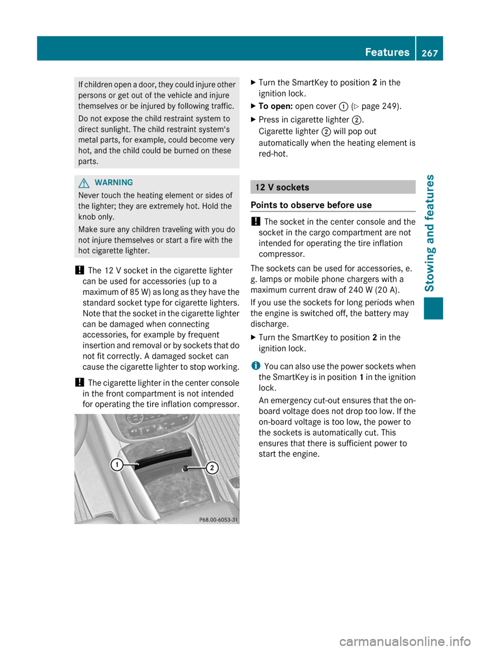
XTurn the SmartKey to position 2 in the
ignition lock.XTo open: open cover : (Y page 249).XPress in cigarette lighter ;.
Cigarette lighter ; will pop out
automatically when the heating element is
red-hot.
12 V sockets
Points to observe before use
! The socket in the center console and the
socket in the cargo compartment are not
intended for operating the tire inflation
compressor.
The sockets can be used for accessories, e.
g. lamps or mobile phone chargers with a
maximum current draw of 240 W (20 A).
If you use the sockets for long periods when
the engine is switched off, the battery may
discharge.
XTurn the SmartKey to position 2 in the
ignition lock.
i You can also use the power sockets when
the SmartKey is in position 1 in the ignition
lock.
An emergency cut-out ensures that the on-
board voltage does not drop too low. If the
on-board voltage is too low, the power to
the sockets is automatically cut. This
ensures that there is sufficient power to
start the engine.
Features267Stowing and featuresZ
Page 270 of 368
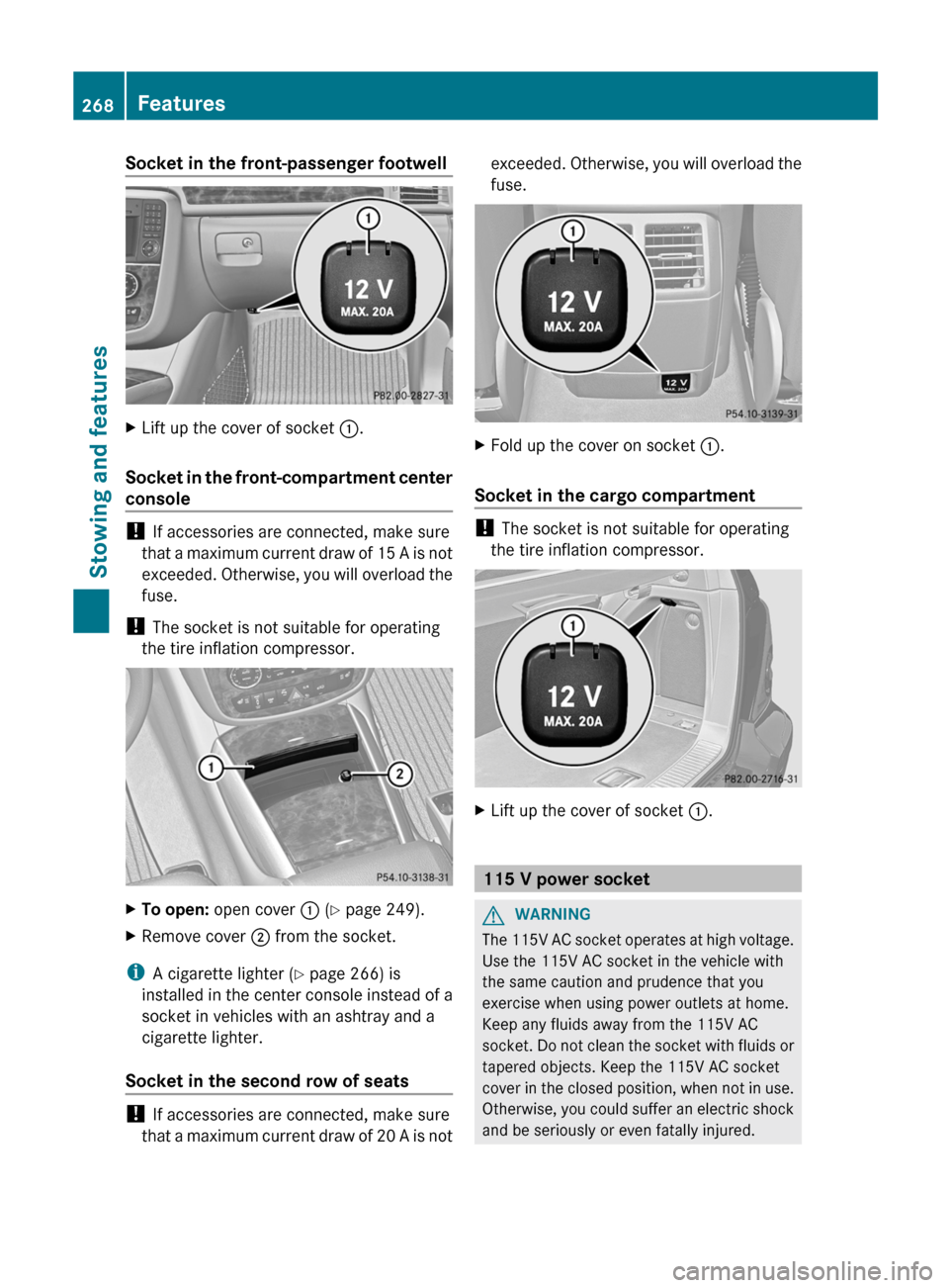
Socket in the front-passenger footwellXLift up the cover of socket :.
Socket in the front-compartment center
console
! If accessories are connected, make sure
that a maximum current draw of 15 A is not
exceeded. Otherwise, you will overload the
fuse.
! The socket is not suitable for operating
the tire inflation compressor.
XTo open: open cover : (Y page 249).XRemove cover ; from the socket.
i
A cigarette lighter ( Y page 266) is
installed in the center console instead of a
socket in vehicles with an ashtray and a
cigarette lighter.
Socket in the second row of seats
! If accessories are connected, make sure
that a maximum current draw of 20 A is not
exceeded. Otherwise, you will overload the
fuse.XFold up the cover on socket :.
Socket in the cargo compartment
!
The socket is not suitable for operating
the tire inflation compressor.
XLift up the cover of socket :.
115 V power socket
GWARNING
The 115V AC socket operates at high voltage.
Use the 115V AC socket in the vehicle with
the same caution and prudence that you
exercise when using power outlets at home.
Keep any fluids away from the 115V AC
socket. Do not clean the socket with fluids or
tapered objects. Keep the 115V AC socket
cover in the closed position, when not in use.
Otherwise, you could suffer an electric shock
and be seriously or even fatally injured.
268FeaturesStowing and features
Page 271 of 368
GWARNING
Any device that you connect must have a
suitable plug and meet U.S. standards. Never
pull at a cable to disconnect a plug from a
115 V AC power socket. Never use a damaged
connection cable. The 115 V AC power socket
must never be connected to another 115 V
AC power source. Do not use a converter with
an earthed plug for the 115 V AC power
socket. This could cause serious injury to you
and/or other people.
GWARNING
If the 115V AC socket is damaged or torn out
of the trim, do not use or touch the 115V AC
socket. Using a 115V AC socket that is
damaged or torn out of the trim could cause
serious personal injury to you and/or others.
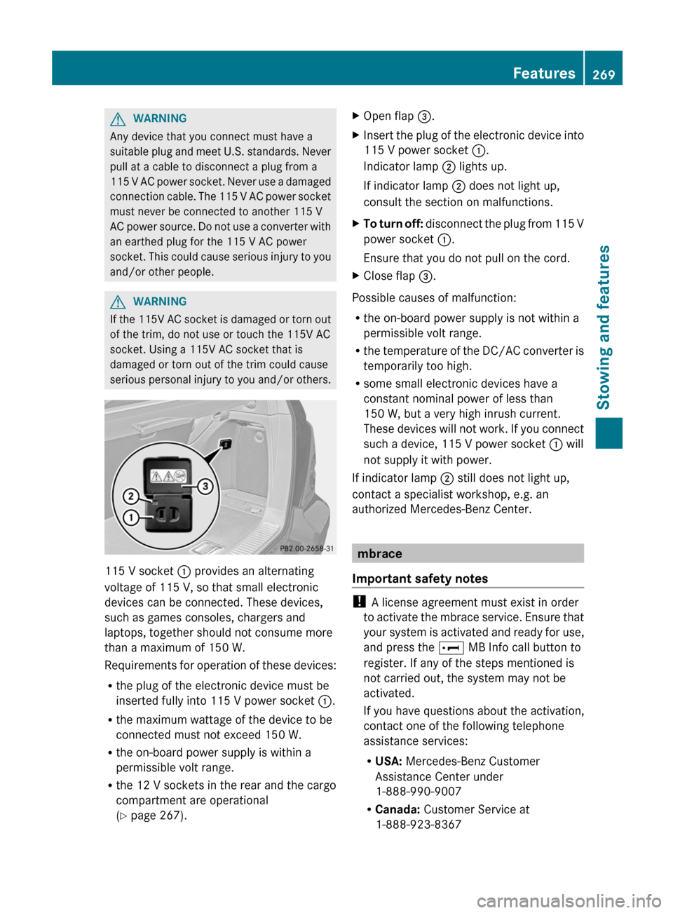
115 V socket : provides an alternating
voltage of 115 V, so that small electronic
devices can be connected. These devices,
such as games consoles, chargers and
laptops, together should not consume more
than a maximum of 150 W.
Requirements for operation of these devices:
R the plug of the electronic device must be
inserted fully into 115 V power socket :.
R the maximum wattage of the device to be
connected must not exceed 150 W.
R the on-board power supply is within a
permissible volt range.
R the 12 V sockets in the rear and the cargo
compartment are operational
( Y page 267).
XOpen flap =.XInsert the plug of the electronic device into
115 V power socket :.
Indicator lamp ; lights up.
If indicator lamp ; does not light up,
consult the section on malfunctions.XTo turn off: disconnect the plug from 115 V
power socket :.
Ensure that you do not pull on the cord.XClose flap =.
Possible causes of malfunction:
R the on-board power supply is not within a
permissible volt range.
R the temperature of the DC/AC converter is
temporarily too high.
R some small electronic devices have a
constant nominal power of less than
150 W, but a very high inrush current.
These devices will not work. If you connect
such a device, 115 V power socket : will
not supply it with power.
If indicator lamp ; still does not light up,
contact a specialist workshop, e.g. an
authorized Mercedes-Benz Center.
mbrace
Important safety notes
! A license agreement must exist in order
to activate the mbrace service. Ensure that
your system is activated and ready for use,
and press the E MB Info call button to
register. If any of the steps mentioned is
not carried out, the system may not be
activated.
If you have questions about the activation,
contact one of the following telephone
assistance services:
R USA: Mercedes-Benz Customer
Assistance Center under
1-888-990-9007
R Canada: Customer Service at
1-888-923-8367
Features269Stowing and featuresZ
Page 274 of 368
Mercedes-Benz Customer Assistance Center
will automatically contact local emergency
officials with the vehicle's approximate
location if they receive an automatic SOS
signal and cannot make voice contact with the
vehicle occupants.
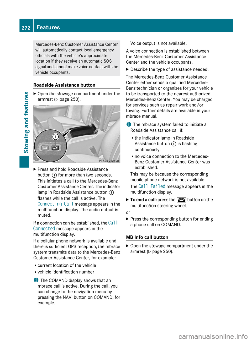
Roadside Assistance buttonXOpen the stowage compartment under the
armrest ( Y page 250).XPress and hold Roadside Assistance
button : for more than two seconds.
This initiates a call to the Mercedes-Benz
Customer Assistance Center. The indicator
lamp in Roadside Assistance button :
flashes while the call is active. The
Connecting Call message appears in the
multifunction display. The audio output is
muted.
If a connection can be established, the Call
Connected message appears in the
multifunction display.
If a cellular phone network is available and
there is sufficient GPS reception, the mbrace
system transmits data to the Mercedes-Benz
Customer Assistance Center, for example:
R current location of the vehicle
R vehicle identification number
i The COMAND display shows that an
mbrace call is active. During the call, you
can change to the navigation menu by
pressing the NAVI button on COMAND, for
example.
Voice output is not available.
A voice connection is established between
the Mercedes-Benz Customer Assistance
Center and the vehicle occupants.XDescribe the type of assistance needed.
The Mercedes-Benz Customer Assistance
Center either sends a qualified Mercedes-
Benz technician or organizes for your vehicle
to be transported to the nearest authorized
Mercedes-Benz Center. You may be charged
for services such as repair work and/or
towing. Further details are available in your
mbrace manual.
i The mbrace system failed to initiate a
Roadside Assistance call if:
R the indicator lamp in Roadside
Assistance button : is flashing
continuously.
R no voice connection to the Mercedes-
Benz Customer Assistance Center was
established.
This may be because the corresponding
mobile phone network is not available.
The Call Failed message appears in the
multifunction display.
XTo end a call: press the ~ button on the
multifunction steering wheel.
or
XPress the corresponding button for ending
a phone call on COMAND.
MB Info call button
XOpen the stowage compartment under the
armrest ( Y page 250).272FeaturesStowing and features
Page 276 of 368
iYou can only use the Destination
Download function if the vehicle is
equipped with a navigation system.
Destination Download gives you access to a
database with over 15 million points of
interest (POIs)/important destinations that
can be downloaded onto the navigation
system of your vehicle. If you know the
destination, you can download the address or
obtain the location of points of interest
(POIs)/important destinations in the
surrounding area.
You are prompted to confirm route guidance
to the address entered.XSelect Yes with the = or ; buttons
on COMAND.XPress the 9 button on COMAND to
confirm.
The system calculates the route and
subsequently starts the route guidance with
the address entered.
i If you select No, the address can be stored
in the address book.
i The Destination Download function is
available if the corresponding mobile
phone network is available and data
transfer is possible.
Route Assistance
This service is part of the mbrace PLUS
Package and cannot be purchased
separately.
i You can also use the Route Assistance
function if your vehicle is not equipped with
a navigation system.
Within the framework of this service, you
receive a professional and reliable form of
navigation support without having to leave
your vehicle.
The customer service representative
determines a suitable driving route based on
your current vehicle position and the desired
destination and guides you live through the
current sections of the route.
Search & Send
"Search & Send" is a destination entry
service. You can find further information on
"Search & Send" in the separate COMAND
operating instructions.
Vehicle remote opening
If you have unintentionally locked your
vehicle (e.g. the SmartKey is still in the
vehicle) and a replacement SmartKey is not
available, the vehicle can be opened by a
Mercedes-Benz Customer Assistance Center.
The vehicle can be opened remotely up to four
days after the ignition was last switched off.
XContact the following service hotlines:
R USA: Mercedes-Benz Customer
Assistance Center under 1-800-FOR-
MERCedes(1-800-367-6372) or
1-888-990-9007
R Canada: Customer Service at
1-888-923-8367
You will be asked for your password.XReturn to your vehicle at the time agreed
upon with the Mercedes-Benz Customer
Assistance Center.XPull the tailgate handle for at least 20
seconds until the indicator lamp in the SOS
button ( Y page 270) flashes.
The Connecting Call message appears
on the multifunction display.
Alternatively, the vehicle can also be opened
via the Internet or an iPhone in the "Owners
Online" section using your ID number and
password 34
.
i Vehicle remote unlocking is only possible
if the corresponding mobile phone network
is accessible.
The SOS button flashes and the Call
Connected message appears in the
multifunction display to confirm that the
34 USA only.274FeaturesStowing and features