display MERCEDES-BENZ S-CLASS SALOON LONG 2020 User Guide
[x] Cancel search | Manufacturer: MERCEDES-BENZ, Model Year: 2020, Model line: S-CLASS SALOON LONG, Model: MERCEDES-BENZ S-CLASS SALOON LONG 2020Pages: 609, PDF Size: 10.5 MB
Page 56 of 609
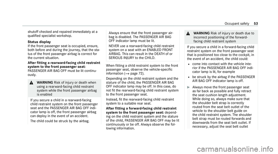
shutoff
checked and repaired immediately at a
qu alified specialist workshop.
St atus display
If th e front passenger seat is occupied, ensure,
bo th before and during the journe y,that thest a‐
tus of the front passenger airbag is cor rect for
th e cur rent situation.
Af terfitting a rear wa rd-facing child restra int
sy stem tothe front passenger seat:
PA SSENGER AIR BAG OFF must be lit continu‐
ousl y. &
WARNING Risk of inju ryor death when
using a rear wa rd-facing child restra int
sy stem while the front passenger airbag
is enabled
If yo u secure a child in a rear wa rd-facing
ch ild restra int sy stem on the front passenger
seat and thePA SSENGER AIR BAG OFF indi‐
cator lamp is off, the front passenger airbag
can deploy in theev ent of an accident.
The child could be stru ck bythe airbag. Alw
ays ensure that the front passenger air‐
bag is disabled. The PASSENGER AIR BAG
OFF indicator lamp must be lit.
NEVER use a rear wa rd-facing child restra int
sy stem on a seat with an ENABLED FRONT
AIRB AG. This can result in the DEAT H of or
SERIOUS INJU RYtotheCH ILD. When
fitting a child restra int sy stem tothe front
passenger seat, obser vetheve hicle-specific
information (/ page72).
Depending on thech ild restra int sy stem and the
st ature of thech ild, thePA SSENGER AIR BAG
OFF indicator lamp may be off. In this case, do
not fit th ere ar wa rd-facing child restra int sy stem
to the front passenger seat.
Ins tead, fit th ere ar wa rd-facing child restra int
sy stem toa suitable rear seat.
Af terfitting a forw ard-facing child restra int
sy stem tothe front passenger seat: depend‐
ing on thech ild restra int sy stem and thest ature
of thech ild, PASSENGER AIR BAG OFF may be lit
continuously or be off. Alw ays obser vethefo l‐
lowing information. &
WARNING Risk of inju ryor death due to
incor rect positioning of thefo rw ard-
fa cing child restra int sy stem
If yo u secure a child in a forw ard-facing child
re stra int sy stem on the front passenger seat
th at is positioned too close tothe cockpit, in
th eev ent of an accident, thech ild could:
R come into con tact wi th theve hicle inte‐
ri or if thePA SSENGER AIR BAG OFF indi‐
cator lamp is lit, forex ample
R bestru ck bythe airbag if thePA SSENGER
AIR BAG OFF indicator lamp is off. #
Alw ays mo vethe front passenger seat
as far back as possible and fully retract
th e seat cushion length adjustment.
While doing so, alw ays make sure that
th e shoulder belt stra p is cor rectly
ro uted from the seat belt outlet of the
ve hicle tothe shoulder belt guide on
th ech ild restra int sy stem. The shoulder
belt stra p must be routed forw ards and
down wards from the seat belt outlet. If
necessar y,adjust the seat belt outlet Occupant saf
ety53
Page 59 of 609
Sy
stem limits
The sy stem will not initiate any action in thefo l‐
lowing situations:
R when reve rsing
or
R when theve hicle is towing a trailer and there
is a risk of a rear impact
The sy stem will not initiate any braking applica‐
tion in thefo llowing situations:
R whilst driving
or
R when entering or exiting a parking space
while using Active Parking Assist Fu
nction of PRE-SAFE ®
Impulse Side If an imminent side impact is de
tected, PRE-
SA FE®
Impulse Side can pre-emptively mo vethe
front seat vehicle occupant's upper body
to wa rdsth e cent reoftheve hicle. It does this by
ra pidly inflating an air cushion in the outer seat
side bols ter of the seat backrest on the side on
which the impact is anticipated. This increases th
e dis tance between the door and theve hicle
occupant.
If PRE-SAFE ®
Impulse Side has been deplo yed or
is faulty, thePRE-SAFE impulse side inoperative
See Owner's Manual( /page 493) display mes‐
sage appears. Au
tomatic measures af ter an accident
Depending on the type and se verity of the acci‐
dent, and depending on theve hicle's equipment,
th efo llowing measures can be implemen ted, for
ex ample:
R automatic braking (post-collision brake)
R activating the hazard warning lights
R triggering an automatic emer gency call
(/ page 334)
R switching off the engine
To restart theve hicle, switch the ignition off
and switch it back on (/ page189).
Depending on the type and se verity of the
accident, it is possible that theve hicle can
no longer be star ted. R
switching off the fuel supply
R unlocking theve hicle doors
R lowe ring the side windo ws
R displaying the emer gency guide in the cent ral
display
R switching on the interior lighting
Fu nction of the post-collision brake
Depending on the accident situation, the post-
collision brake can minimise the se verity of a fur‐
th er collision or evenavo id it.
If an accident is de tected, the post-collision
brake can implement automatic braking. When
th eve hicle has come toast andstill, the electric
parking brake is automatically applied.
The driver can cancel automatic braking bytak‐
ing thefo llowing actions:
R braking more stronglythan automatic brak‐
ing
R fully depressing the accelerator pedal with
fo rce 56
Occupant saf ety
Page 134 of 609
Yo
u can sa vethefo llowing settings forth e front
seat:
R Seat, backrest, head restra int position and
con tour of the seat backrest in the lumbar
re gion
R Vehicles with an active multicontour
seat:
- Side bols ters of the seat backrest
- Shoulder of the seat backrest
- Contour of the seat backrest
- Dynamic function le vel
R Seat heating: di stribution of the heated sec‐
tions of the seat cushion and seat backrest
R Driver's side: steering wheel position and
position of the outside mir rors on the driver's
and front passenger sides
R Head-up display (depending on vehicle equip‐
ment) Operating
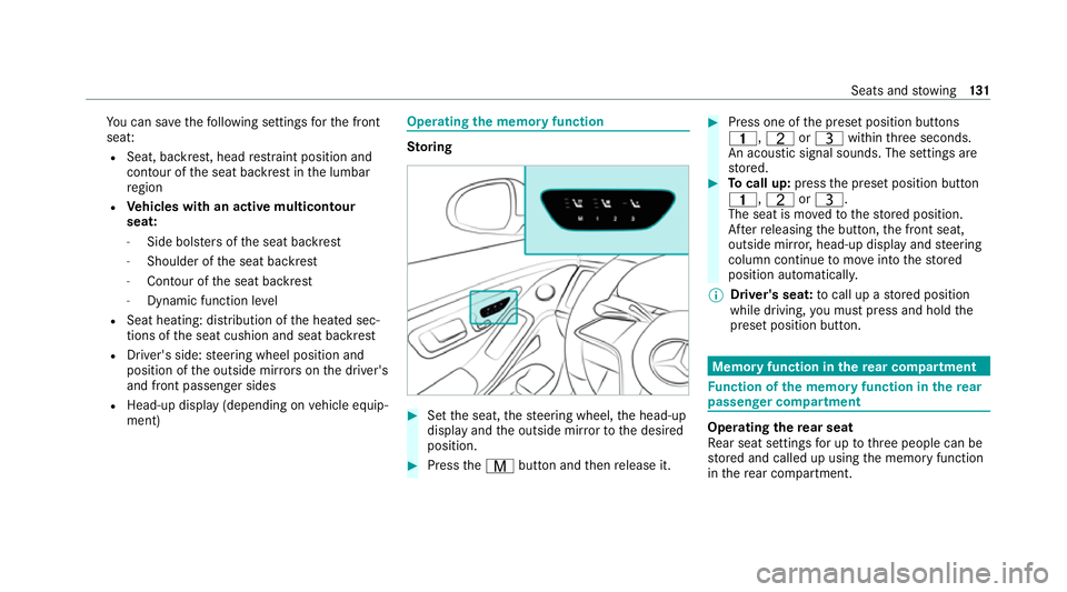
the memory function St
oring #
Set the seat, thesteering wheel, the head-up
display and the outside mir rorto the desired
position. #
Press theV button and then release it. #
Press one of the preset position buttons
4, TorU within thre e seconds.
An acoustic signal sounds. The settings are
st ored. #
Tocall up: pressthe preset position button
4, TorU.
The seat is mo vedto thestored position.
Af terre leasing the button, the front seat,
outside mir ror,head-up display and steering
column continue tomo veinto thestored
position automaticall y.
% Driver's sea t:to call up a stored position
while driving, you must press and hold the
preset position button. Memory function in
there ar comp artment Fu
nction of the memory function in there ar
passenger comp artment Operating
there ar seat
Re ar seat settings for up tothre e people can be
st ored and called up using the memory function
in there ar compartment. Seats and
stowing 131
Page 140 of 609
3
Stow age compartment in the front cent re
console wi thcup holders, USB ports and
ch arging module for wireless charging of
mobile phones
4 Stow age compartment in front of the cent ral
display of the multimedia sy stem
5 Glovecompa rtment
% The rubber mat in thestow age compartment
in front centre console 3can be remo ved
fo r cleaning with clea r,luk ewarm wate r.
Please comply with the no tes on caring for
th e interior (/ page 358). Re
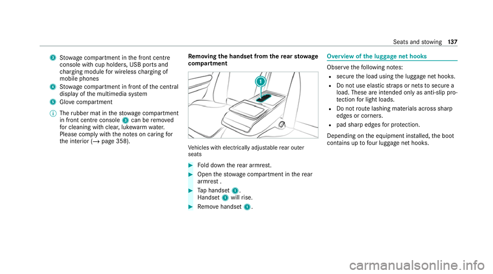
moving the handset from the rear sto wage
compa rtment Ve
hicles with electrically adjus table rear outer
seats #
Fold down there ar armrest. #
Open thestow age compartment in there ar
armrest . #
Tap handset 1.
Handset 1will rise. #
Remo vehandset 1. Overview of
the luggage net hooks Obser
vethefo llowing no tes:
R secure the load using the luggage net hooks.
R Do not use elastic stra ps or nets tosecure a
load. These are intended only as anti-slip pro‐
te ction for light loads.
R Do not route lashing materials across sharp
edges or co rners.
R pad sharp edges for pr otection.
Depending on the equipment ins talled, the boot
conta ins up tofour luggage net hooks. Seats and
stowing 137
Page 152 of 609
R
Depending on theve hicle equipment, the
mobile phone is connected totheve hicle's
ex terior aerial via thech arging module.
R The charging function and wireless connec‐
tion of the mobile phone totheve hicle's
ex terior aerial are only available if the ignition
is switched on.
R Small mobile phones may not be able tobe
ch arge d in everyposition of the mobile
phone stowage compartment.
R Largemobile phones which do not rest flat in
th e mobile phone stowage compartment may
not be able tobe charge d or connec ted with
th eve hicle's exterior aerial.
R The mobile phone may heat up during the
ch arging process. This may also depend on
th e applications (apps) cur rently open in the
bac kground.
R Toensure more ef ficient charging and con‐
nection with theve hicle's exterior aerial,
re mo vethe pr otective co ver from the mobile
phone. Pr otective co vers which are neces‐
sary for wireless charging are an exception. Wire
lessly charging a mobile phone in the
front Re
quirements:
R The mobile phone is suitable for wireless
ch arging.
A list of compatible mobile phones can be
fo und at: https://www.mercedes-benz-
mobile.com/
Depending on theve hicle's equipment, theve hi‐
cle has thefo llowing options for wirelessly
ch arging the mobile phone in the cockpit:
R Inthe front stowage compartment
R Inthestow age compartment of the cockpit
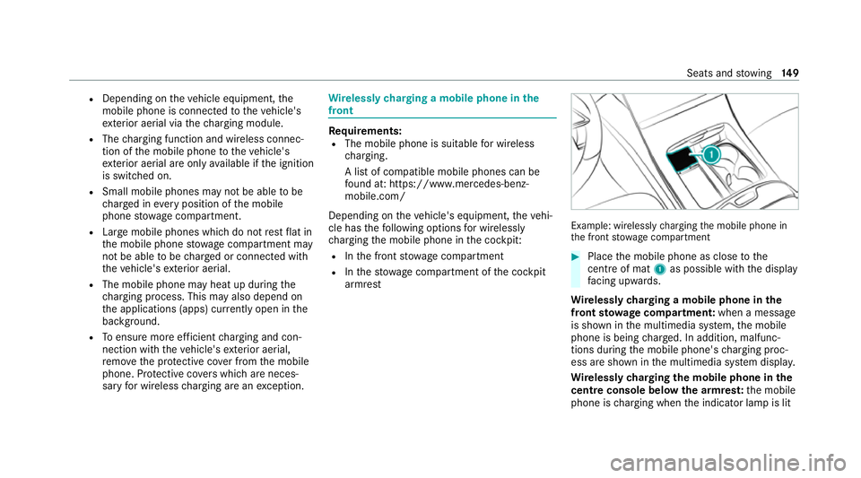
armrest Example: wirelessly
charging the mobile phone in
th e front stowage compartment #
Place the mobile phone as close tothe
centre of mat 1as possible wi th the display
fa cing up wards.
Wire lessly charging a mobile phone in the
front stowage compa rtmen t:when a message
is shown in the multimedia sy stem, the mobile
phone is being charge d. In addition, malfunc‐
tions during the mobile phone's charging proc‐
ess are shown in the multimedia sy stem displa y.
Wire lessly charging the mobile phone in the
centre console below the armres t:the mobile
phone is charging when the indicator lamp is lit Seats and
stowing 14 9
Page 153 of 609
up. In addition, malfunctions during
the mobile
phone's charging process are shown bythe indi‐
cator lamp flashing thre e times.
% The mat can be remo vedfo r cleaning, e.g.
using clean, luk ewarmwate r.
Ra dio equipment appr oval numbers for Brazil
This device operates on a secondary basis, that
is to say it has no pr otection against harmful
inter fere nce, not even from the same type of
st ations, and must not cause inter fere nce wi th
sy stems operating on a primary basis.
This product is permitted in accordance with the
procedure defined in Directive 242/2000 bythe
Brazilian telecommunications agency AN ATEL
and meets the applicable tech nical requ ire‐
ments.
Fu rther information is available on the AN ATEL
we bsite. www.anatel.go v.br #
Further information on the declaration of
confo rmity forve hicle components which
re cei veand/or transmit radio wav es. Wire
lessly charging a mobile phone in the
re ar passenger comp artment Re
quirements:
R The mobile phone is suitable for wireless
ch arging.
A list of compatible mobile phones can be
fo und at: https://www.mercedes-benz-
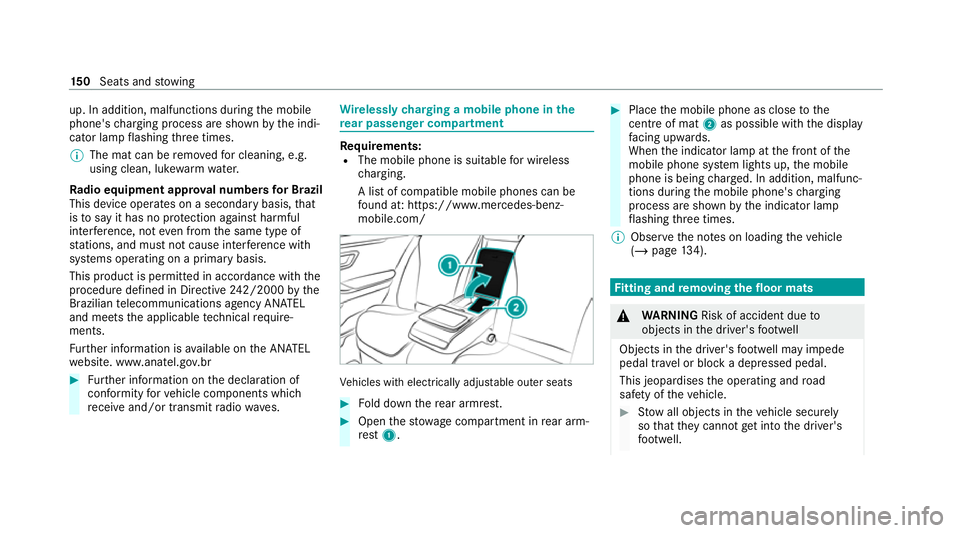
mobile.com/ Ve
hicles with electrically adjus table outer seats #
Fold down there ar armrest. #
Open thestow age compartment in rear arm‐
re st 1 . #
Place the mobile phone as close tothe
centre of mat 2as possible wi th the display
fa cing up wards.
When the indicator lamp at the front of the
mobile phone sy stem lights up, the mobile
phone is being charge d. In addition, malfunc‐
tions during the mobile phone's charging
process are shown bythe indicator lamp
fl ashing thre e times.
% Obser vethe no tes on loading theve hicle
(/ page 134). Fi
tting and removing the floormats &
WARNING Risk of accident due to
objects in the driver's foot we ll
Objects in the driver's foot we ll may impede
pedal tr avel or block a depressed pedal.
This jeopardises the operating and road
saf ety of theve hicle. #
Stow all objects in theve hicle securely
so that they cannot getinto the driver's
fo ot we ll. 15 0
Seats and stowing
Page 155 of 609
Exterior lighting
Note
s on adjusting the lights when driving
abroad The headlamps will automatically be adjus
ted
when theve hicle crosses the border into coun‐
tries in which tra ffic drives on theot her side of
th ero ad and will retain their full range of func‐
tions. If necessa ry,th e headlamps can also be
adjus ted manually in theLow beam menu
(/ page 161).
In thefo llowing cases, check the setting of the
headlamp s andchange it manually if necessary:
R Ifth eDipped-beam setting (left/right-side
traffic) Manual adjustment only display mes‐
sage is displa yed.
R Ifth eCheck dipped-beam setting (left/right-
side traffic) display message is displa yed.
Fo llowing manual adjustment:
R Oncoming traf fic will not be dazzled.
R The edge of thero ad will not be illuminated
as far or as high. R
The "mo torw ay mode" and "enhanced fog
light" functions will not be available. Information about lighting sy
stems and your
re sponsibility The
various lighting sy stems of theve hicle are
only aids. The driver of theve hicle is responsible
fo r cor rect vehicle illumination in accordance
with the pr evailing light and visibility conditions,
legal requ irements and traf fic situation. Light switch
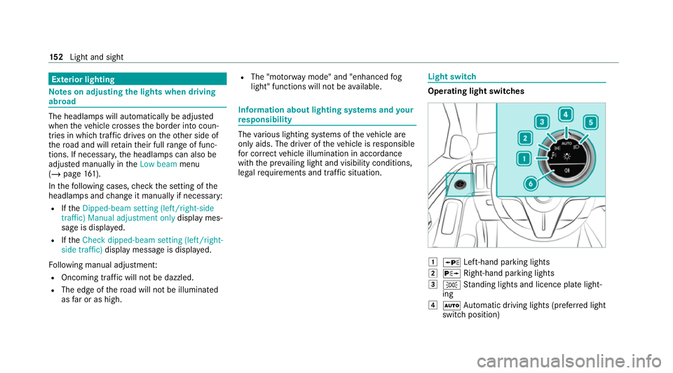
Ope
rating light switches 1
W Left-hand pa rking lights
2 X Right-hand parking lights
3 T Standing lights and licence plate light‐
ing
4 Ã Automatic driving lights (prefer red light
switch position) 15 2
Light and sight
Page 160 of 609
The function is automatically deactivated under
th efo llowing conditions:
R Atspeeds abo ve100 km/h af ter activation.
R When there ar fog light is switched off.
Fu nction of the bad weather light
The bad weather light reduces reflections in
ra iny conditions bydimming individual LEDs in
th e headlamps. The driver and other road users
are dazzled less as a result.
The city lighting function
City lighting impr ovesth e illumination of road‐
sides in urban areas using a broad distribution of
light.
The function is active in thefo llowing cases:
R Atlow speeds
R In illuminated parts of urban areas
Fu nction of theto pog raphical co mpensation
Based on map data, the lighting sy stem
re sponds pre-em ptively todiffere nt road heights.
This means that the headlamp range remains vir‐
tually cons tant when you are driving on uphill or
downhill gradients. %
The availability of the function is dependent
on the count ry.
Assistance functions of the DIGITAL LIGHT
DIGITAL LIGHT visually expands on the driver
assis tance sy stems byprojecting the assis tant
displ ays in front of theve hicle while it is in
motion. DIGITAL LIGHT can therefore help the
driver in critical situations.
% The availability of the functions is dependent
on the count ry.
The sy stem is active in thefo llowing cases:
R The light switch is in theà position.
R The high beam is switched on.
% Ifyo u activate the head-up display with aug‐
mented realit y,the projections can be deac‐
tivated depending on the situation.
% Depending on the count ryin which you are
cur rently driving, cer tain functions may be
disabled due todiffere nt le galre qu irements,
eve n if they are enabled in the multimedia
sy stem. When a border is crossed, theve hi‐
cle will automatically adapt totheva lid
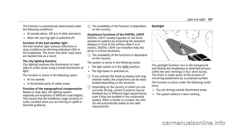
re qu irements. Spotlight
The spotlight function
runs in the bac kground
and flashes the headlamps at de tected persons
wi thin the lane markings in four sho rtbur sts.
The driver is made aware of the position of
oncoming pedestrians bya projected symbol.
The function is active under thefo llowing condi‐
tions:
R You are driving outside illuminated areas.
R The sy stem de tects a lane marking. Light and sight
157
Page 169 of 609
Fi
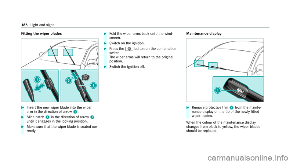
tting the wiper blades #
Inse rtthe new wiper blade into the wiper
arm in the direction of ar row1. #
Slide catch 2inthe direction of ar row 3
until it engages in the locking position. #
Make sure that the wiper blade is seated cor‐
re ctly. #
Foldthe wiper arms back onto the wind‐
screen. #
Switch on the ignition. #
Press theî button on the combination
switch.
The wiper arms will return tothe original
position. #
Switch the ignition off. Maintenance display #
Remo veprotective film 1 from the mainte‐
nance display on the tip of the newly fitted
wiper blades.
When the colour of the maintenance display
ch anges from black to yellow, the wiper blades
should be replaced. 16 6
Light and sight
Page 176 of 609
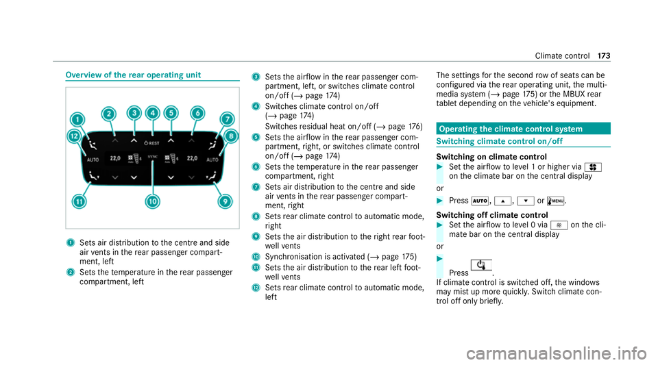
Overview of
there ar operating unit 1
Sets air distribution tothe cent reand side
air vents in there ar passenger compart‐
ment, left
2 Sets thete mp erature in there ar passenger
compartment, left 3
Sets the air flow inthere ar passenger com‐
partment, left, or swit ches climate control
on/off (/ page174)
4 Switches climate control on/off
(/ page 174)
Switches residual heat on/off (/ page176)
5 Sets the air flow inthere ar passenger com‐
partment, right, or switches climate control
on/off (/ page174)
6 Sets thete mp erature in there ar passenger
compartment, right
7 Sets air distribution tothe cent reand side
air vents in there ar passenger compart‐
ment, right
8 Sets rear climate control toautomatic mode,
ri ght
9 Sets the air distribution totheright rear foot‐
we llve nts
A Synchronisation is acti vated (/ page175)
B Sets the air distribution tothere ar left foot‐
we llve nts
C Sets rear climate control toautomatic mode,
left The settings
forth e second rowof seats can be
configured via there ar operating unit, the multi‐
media sy stem (/ page175) or the MBUX rear
ta blet depending on theve hicle's equipment. Operating
the clima tecont rol sy stem Switching clima
tecont rol on/off Switching on climate control
#
Set the air flow toleve l 1 or higher via J
on the climate bar on the cent ral display
or #
Press Ã, s,ror±.
Switching off clima tecont rol #
Set the air flow toleve l 0 via Ionthe cli‐
mate bar on the cent ral display
or #
Press .
If climate control is switched off, the windo ws
may mist up more quickl y.Switch climate con‐
trol off only brie fly. Climate cont
rol17 3