fuse Mercury Monterey 2006 s User Guide
[x] Cancel search | Manufacturer: MERCURY, Model Year: 2006, Model line: Monterey, Model: Mercury Monterey 2006Pages: 320, PDF Size: 3.57 MB
Page 206 of 320
A new underbody wiring harness (14406) will be a component to this kit
and will need to be installed, if applicable, per instructions located in the
service kit.
If your vehicle has the optional trailer tow package it comes with heavy
duty cooling fans, auxiliary transmission fluid cooler, an auxiliary engine
oil cooler, heavy duty battery, trailer tow wiring (including fuses and
relays to isolate the vehicle lighting circuitry from the trailer lighting)
and a kit (in a cardboard box) that includes an adapter wiring harness
that contains the standard 4-pin trailer plug.
Trailer towing puts additional loads on your vehicle’s engine,
transmission, axle, brakes, tires, and suspension. For your safety and to
maximize vehicle performance, be sure to use the proper equipment
while towing.
Follow these guidelines to ensure safe towing procedure:
•Stay within your vehicle’s load limits. If exceeded, cargo should be
removed from the trailer and/or the vehicle until all weights are within
specified limits.
•Thoroughly prepare your vehicle for towing. Refer toPreparing to
towin this chapter.
•Use extra caution when driving while trailer towing. Refer toDriving
while you towin this chapter.
•Service your vehicle more frequently if you tow a trailer. Refer to
Special Operating Conditionsin the scheduled maintenance
information.
•Do not tow a trailer until your vehicle has been driven at least
500 miles (800 km).
•Refer to the instructions included with towing accessories for the
proper installation and adjustment specifications.
2006 Monterey(mty)
Owners Guide (post-2002-fmt)
USA(fus)
Tires, Wheels and Loading
206
Page 219 of 320

If the steering wanders or pulls, check for:
•an improperly inflated tire
•uneven tire wear
•loose or worn suspension components
•loose or worn steering components
•improper steering alignment
A high crown in the road or high crosswinds may also make the steering
seem to wander/pull.
AUTOMATIC TRANSAXLE OPERATION
Brake-shift interlock
This vehicle is equipped with a brake-shift interlock feature that prevents
the gearshift lever from being moved from P (Park) when the ignition is
in the 4 (ON) position unless the brake pedal is depressed.
If you cannot move the gearshift lever out of P (Park) with the ignition
in the 4 (ON) position and the brake pedal depressed:
1. Apply the parking brake.
2. Insert the key and turn it to the 3
(OFF) position.Apply the brake
pedal and shift to N (Neutral).
When the key is in the ignition and in the 3 (OFF) position, the
automatic transmission shift lever can be moved from the P
(Park) position without the brake pedal depressed. To avoid unwanted
vehicle movement, always set the parking brake.
3. Start the vehicle.
If it is necessary to use the above procedure to move the gearshift lever,
it is possible that a fuse has blown or the vehicle’s brakelamps are not
operating properly. Refer toFuses and relaysin theRoadside
Emergencieschapter.
3
1
2
5
4
2006 Monterey(mty)
Owners Guide (post-2002-fmt)
USA(fus)
Driving
219
Page 229 of 320

This switch is located behind the
service panel on the right side of
the cargo area.
To reset the switch:
1. Turn the ignition OFF.
2. Check the fuel system for leaks.
3. If no leaks are apparent, reset the
switch by pushing in on the reset
button.
4. Turn the ignition ON.
5. Wait a few seconds and return
the key to OFF.
6. Make another check for leaks.
FUSES AND RELAYS
Fuses
If electrical components in the
vehicle are not working, a fuse may
have blown. Blown fuses are
identified by a broken wire within
the fuse. Check the appropriate
fuses before replacing any electrical
components.
Note:Always replace a fuse with one that has the specified amperage
rating. Using a fuse with a higher amperage rating can cause severe wire
damage and could start a fire.
15
2006 Monterey(mty)
Owners Guide (post-2002-fmt)
USA(fus)
Roadside Emergencies
229
Page 230 of 320

Standard fuse amperage rating and color
COLOR
Fuse
ratingMini
fusesStandard
fusesMaxi
fusesCartridge
maxi
fusesFuse link
cartridge
2A Grey Grey — — —
3A Violet Violet — — —
4A Pink Pink — — —
5A Tan Tan — — —
7.5A Brown Brown — — —
10A Red Red — — —
15A Blue Blue — — —
20A Yellow Yellow Yellow Blue Blue
25A Natural Natural — — —
30A Green Green Green Pink Pink
40A — — Orange Green Green
50A — — Red Red Red
60A — — Blue — Yellow
70A — — Tan — Brown
80A — — Natural — Black
Passenger compartment fuse panel
The fuse panel is located below and to the left of the steering wheel by
the brake pedal. Remove the panel cover to access the fuses. To remove
the fuse panel cover, pull up on the latch on the right or left side of the
cover.
To remove a fuse use the fuse puller tool provided on the fuse panel
cover.
2006 Monterey(mty)
Owners Guide (post-2002-fmt)
USA(fus)
Roadside Emergencies
230
Page 231 of 320

The fuses are coded as follows:
Fuse/Relay
LocationFuse Amp
RatingPassenger Compartment Fuse
Panel Description
1 Relay Accessory delay relay 1
2 Relay Accessory delay relay 2
3 10A Front wiper motor Run feed
4 5A B+ feed to outside mirrors
5 20A Vent window power feed/Radio
feed
6 5A Driver door switch
illumination/Passenger door
switch illumination
7 10A Rear wiper Run feed
8 10A Cluster/Electronic Automatic
Temperature Control (EATC) B+
feed, DVD
9 10A Passive Anti-theft System (PATS)
LED feed
10 5A Auxiliary radio
11 5A Auxiliary climate control
system/Power Liftgate
Module/Left and right power
sliding door module/Data Link
Connector (DLC)/Clock B+ feeds
2006 Monterey(mty)
Owners Guide (post-2002-fmt)
USA(fus)
Roadside Emergencies
231
Page 232 of 320
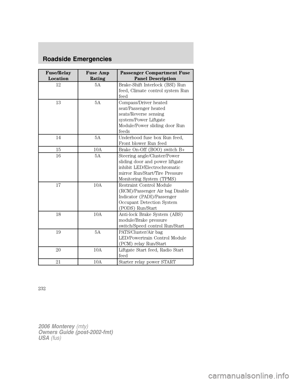
Fuse/Relay
LocationFuse Amp
RatingPassenger Compartment Fuse
Panel Description
12 5A Brake-Shift Interlock (BSI) Run
feed, Climate control system Run
feed
13 5A Compass/Driver heated
seat/Passenger heated
seats/Reverse sensing
system/Power Liftgate
Module/Power sliding door Run
feeds
14 5A Underhood fuse box Run feed,
Front blower Run feed
15 10A Brake On-Off (BOO) switch B+
16 5A Steering angle/Cluster/Power
sliding door and power liftgate
inhibit LED/Electrochromatic
mirror Run/Start/Tire Pressure
Monitoring System (TPMS)
17 10A Restraint Control Module
(RCM)/Passenger Air bag Disable
Indicator (PADI)/Passenger
Occupant Detection System
(PODS) Run/Start
18 10A Anti-lock Brake System (ABS)
module/Brake pressure
switch/Speed control Run/Start
19 5A PATS/Cluster/Air bag
LED/Powertrain Control Module
(PCM) relay Run/Start
20 10A Liftgate Start feed, Radio Start
feed
21 10A Starter relay power START
2006 Monterey(mty)
Owners Guide (post-2002-fmt)
USA(fus)
Roadside Emergencies
232
Page 233 of 320
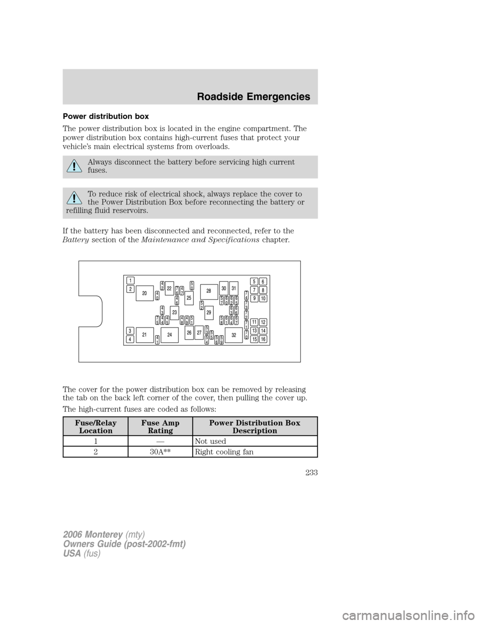
Power distribution box
The power distribution box is located in the engine compartment. The
power distribution box contains high-current fuses that protect your
vehicle’s main electrical systems from overloads.
Always disconnect the battery before servicing high current
fuses.
To reduce risk of electrical shock, always replace the cover to
the Power Distribution Box before reconnecting the battery or
refilling fluid reservoirs.
If the battery has been disconnected and reconnected, refer to the
Batterysection of theMaintenance and Specificationschapter.
The cover for the power distribution box can be removed by releasing
the tab on the back left corner of the cover, then pulling the cover up.
The high-current fuses are coded as follows:
Fuse/Relay
LocationFuse Amp
RatingPower Distribution Box
Description
1 — Not used
2 30A** Right cooling fan
2006 Monterey(mty)
Owners Guide (post-2002-fmt)
USA(fus)
Roadside Emergencies
233
Page 234 of 320
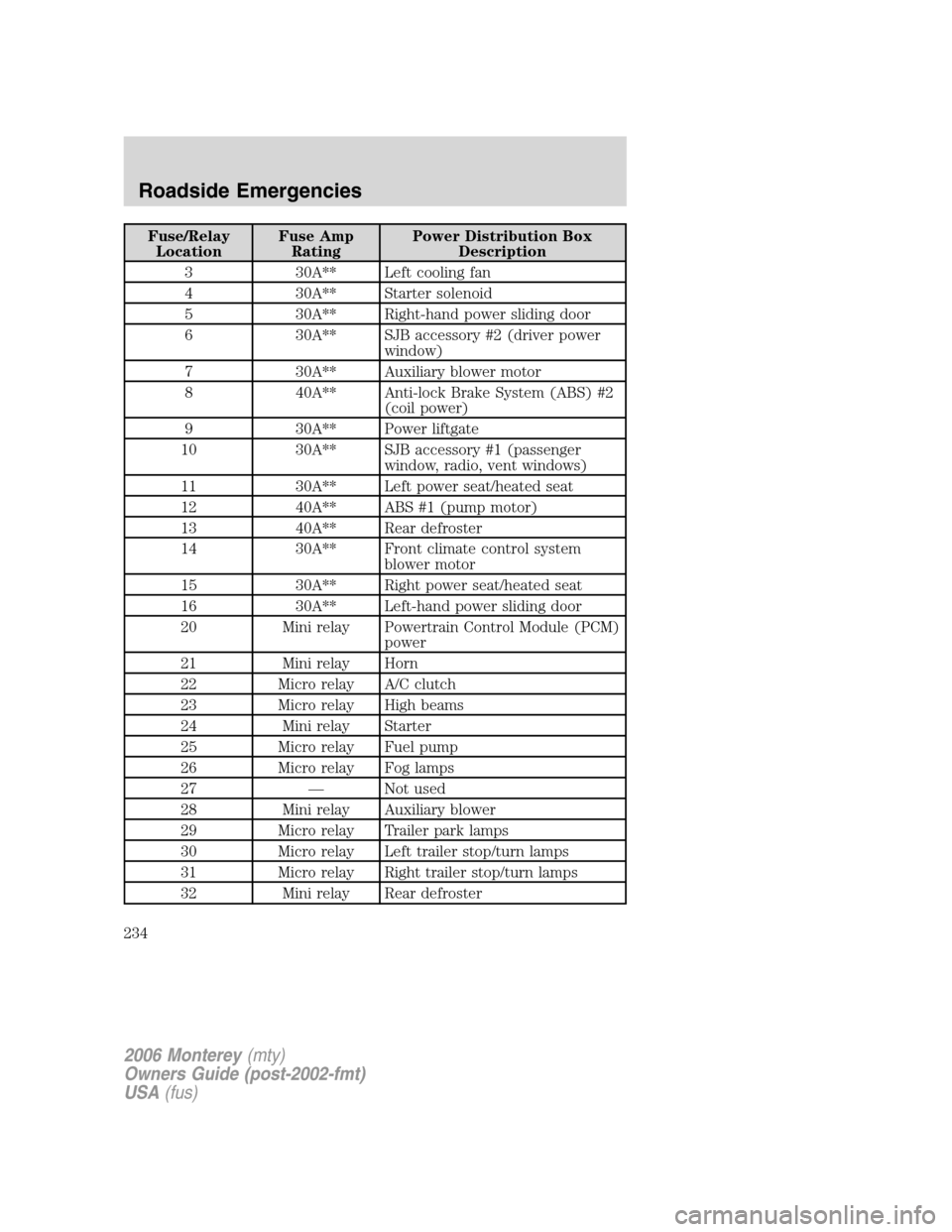
Fuse/Relay
LocationFuse Amp
RatingPower Distribution Box
Description
3 30A** Left cooling fan
4 30A** Starter solenoid
5 30A** Right-hand power sliding door
6 30A** SJB accessory #2 (driver power
window)
7 30A** Auxiliary blower motor
8 40A** Anti-lock Brake System (ABS) #2
(coil power)
9 30A** Power liftgate
10 30A** SJB accessory #1 (passenger
window, radio, vent windows)
11 30A** Left power seat/heated seat
12 40A** ABS #1 (pump motor)
13 40A** Rear defroster
14 30A** Front climate control system
blower motor
15 30A** Right power seat/heated seat
16 30A** Left-hand power sliding door
20 Mini relay Powertrain Control Module (PCM)
power
21 Mini relay Horn
22 Micro relay A/C clutch
23 Micro relay High beams
24 Mini relay Starter
25 Micro relay Fuel pump
26 Micro relay Fog lamps
27 — Not used
28 Mini relay Auxiliary blower
29 Micro relay Trailer park lamps
30 Micro relay Left trailer stop/turn lamps
31 Micro relay Right trailer stop/turn lamps
32 Mini relay Rear defroster
2006 Monterey(mty)
Owners Guide (post-2002-fmt)
USA(fus)
Roadside Emergencies
234
Page 235 of 320
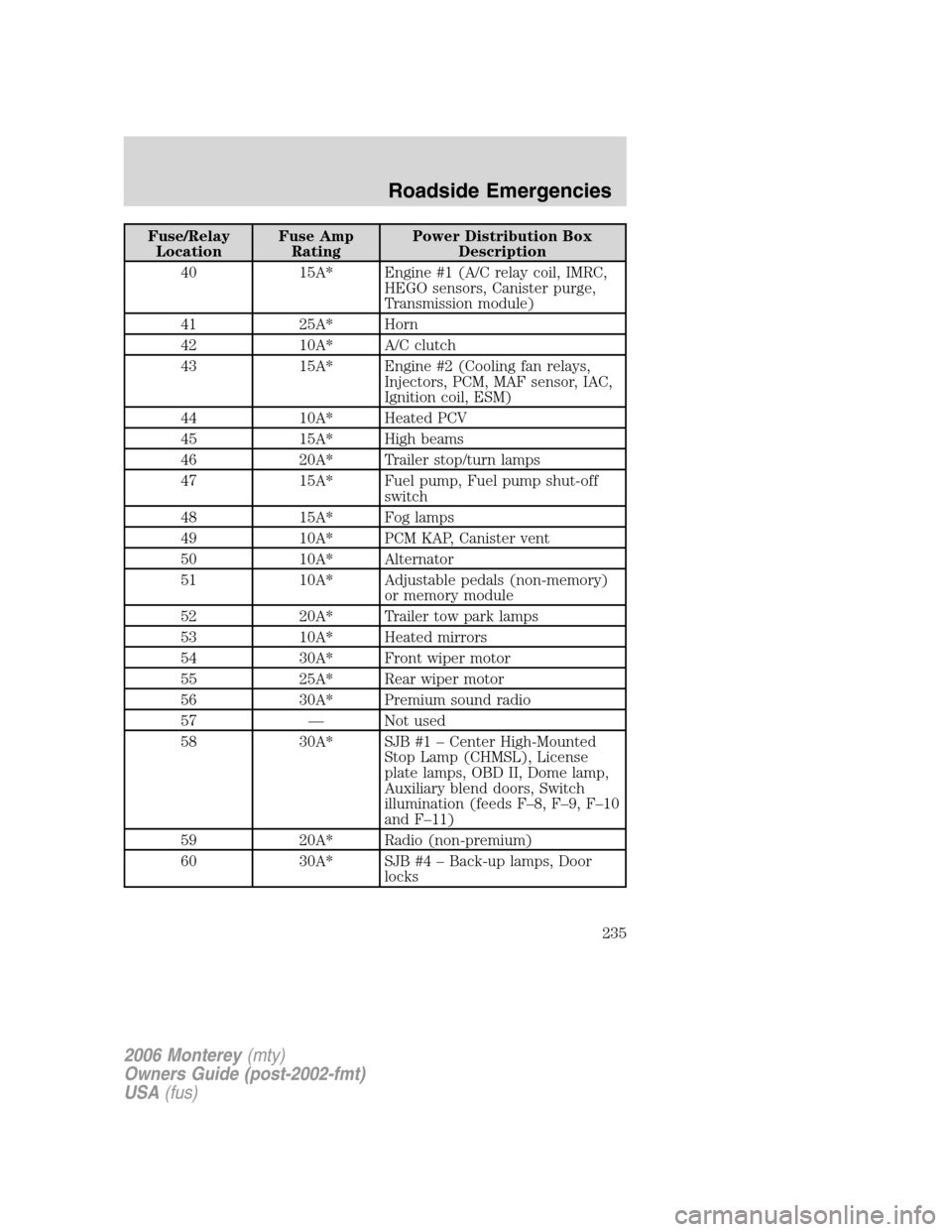
Fuse/Relay
LocationFuse Amp
RatingPower Distribution Box
Description
40 15A* Engine #1 (A/C relay coil, IMRC,
HEGO sensors, Canister purge,
Transmission module)
41 25A* Horn
42 10A* A/C clutch
43 15A* Engine #2 (Cooling fan relays,
Injectors, PCM, MAF sensor, IAC,
Ignition coil, ESM)
44 10A* Heated PCV
45 15A* High beams
46 20A* Trailer stop/turn lamps
47 15A* Fuel pump, Fuel pump shut-off
switch
48 15A* Fog lamps
49 10A* PCM KAP, Canister vent
50 10A* Alternator
51 10A* Adjustable pedals (non-memory)
or memory module
52 20A* Trailer tow park lamps
53 10A* Heated mirrors
54 30A* Front wiper motor
55 25A* Rear wiper motor
56 30A* Premium sound radio
57 — Not used
58 30A* SJB #1 – Center High-Mounted
Stop Lamp (CHMSL), License
plate lamps, OBD II, Dome lamp,
Auxiliary blend doors, Switch
illumination (feeds F–8, F–9, F–10
and F–11)
59 20A* Radio (non-premium)
60 30A* SJB #4 – Back-up lamps, Door
locks
2006 Monterey(mty)
Owners Guide (post-2002-fmt)
USA(fus)
Roadside Emergencies
235
Page 236 of 320
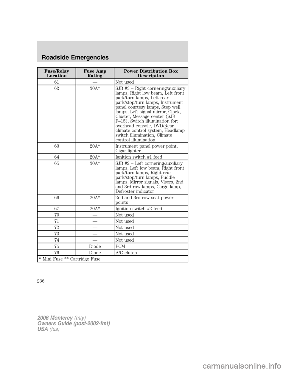
Fuse/Relay
LocationFuse Amp
RatingPower Distribution Box
Description
61 — Not used
62 30A* SJB #3 – Right cornering/auxiliary
lamps, Right low beam, Left front
park/turn lamps, Left rear
park/stop/turn lamps, Instrument
panel courtesy lamps, Step well
lamps, Left signal mirror, Clock,
Cluster, Message center (SJB
F–15), Switch illumination for:
overhead console, DVD/Rear
climate control system, Headlamp
switch illumination, Climate
control illumination
63 20A* Instrument panel power point,
Cigar lighter
64 20A* Ignition switch #1 feed
65 30A* SJB #2 – Left cornering/auxiliary
lamps, Left low beam, Right front
park/turn lamps, Right rear
park/stop/turn lamps, Puddle
lamps, Mirror signals, Visors, 2nd
and 3rd row lamps, Cargo lamp,
Defroster indicator
66 20A* 2nd and 3rd row seat power
points
67 20A* Ignition switch #2 feed
70 — Not used
71 — Not used
72 — Not used
73 — Not used
74 — Not used
75 Diode PCM
76 Diode A/C clutch
* Mini Fuse ** Cartridge Fuse
2006 Monterey(mty)
Owners Guide (post-2002-fmt)
USA(fus)
Roadside Emergencies
236