check engine MINI Clubman 2009 Owner's Manual
[x] Cancel search | Manufacturer: MINI, Model Year: 2009, Model line: Clubman, Model: MINI Clubman 2009Pages: 158, PDF Size: 2.51 MB
Page 15 of 158
REFERENCE
AT A GLANCE CONTROLS DRIVING TIPS MOBILITY
13
Indicator and
warning lamps
The concept
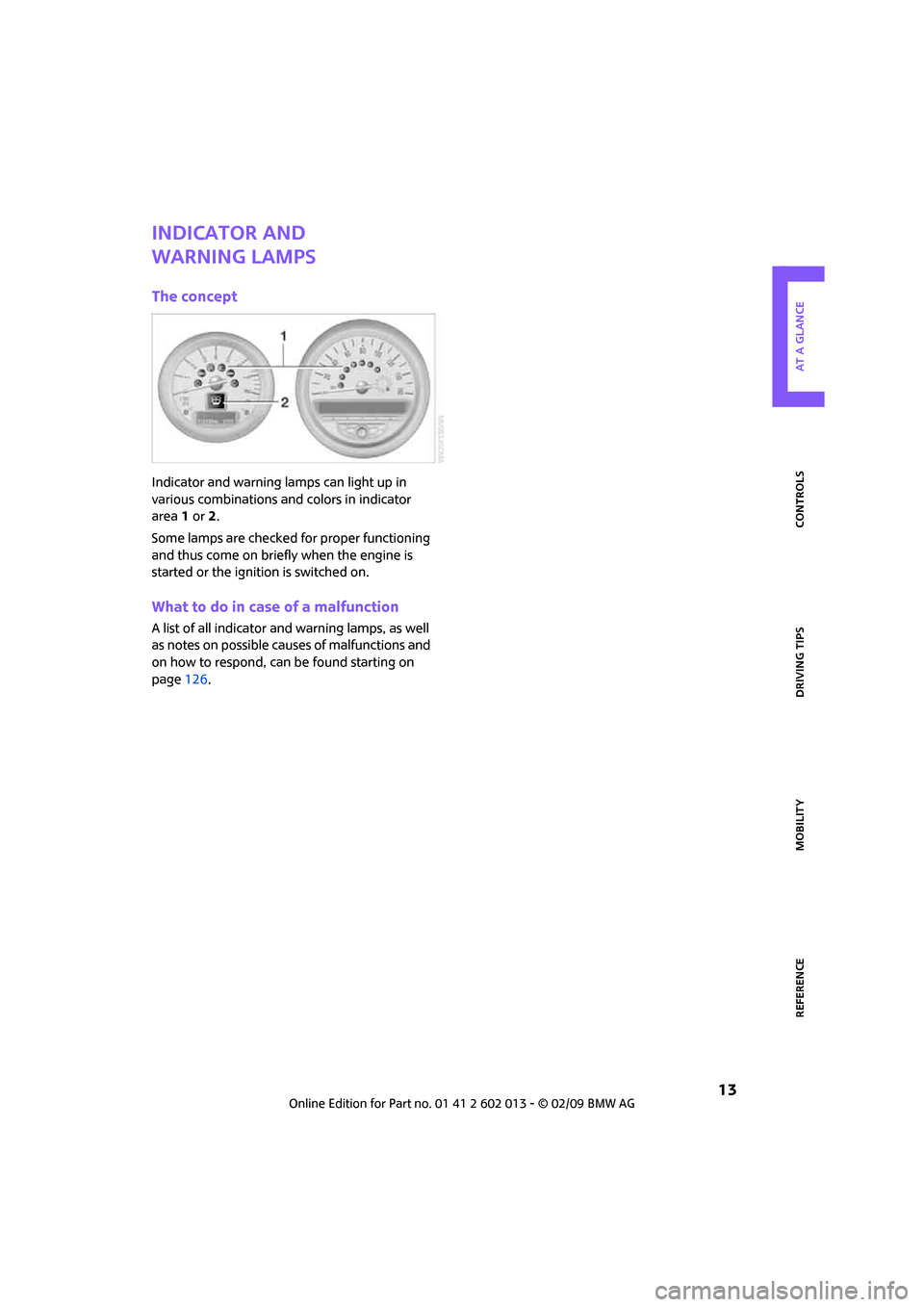
Indicator and warning lamps can light up in
various combinations and colors in indicator
area 1 or2.
Some lamps are checked for proper functioning
and thus come on briefly when the engine is
started or the ignition is switched on.
What to do in case of a malfunction
A list of all indicator and warning lamps, as well
as notes on possible causes of malfunctions and
on how to respond, can be found starting on
page126.
Page 28 of 158
Opening and closing
26
Comparison to standard remote controls
In general, there is no difference between using
convenient access or pressing the buttons on
the remote control to carry out the functions
mentioned above.
Instructions on opening and closing are found
starting on page18.
Special features regarding the use of convenient
access are described below.
If you notice a brief delay while opening or
closing the windows or glass sunroof, the
system is checking whether a remote control is
inside the vehicle. Repeat the opening or closing
procedure, if necessary.<
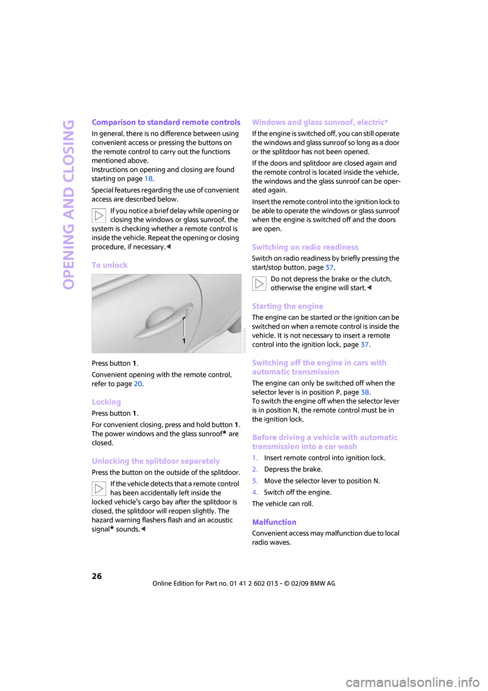
To unlock
Press button 1.
Convenient opening with the remote control,
refer to page20.
Locking
Press button 1.
For convenient closing, press and hold button 1.
The power windows and the glass sunroof
* are
closed.
Unlocking the splitdoor separately
Press the button on the outside of the splitdoor.
If the vehicle detects that a remote control
has been accidentally left inside the
locked vehicle's cargo bay after the splitdoor is
closed, the splitdoor will reopen slightly. The
hazard warning flashers flash and an acoustic
signal
* sounds.<
Windows and glass sunroof, electric*
If the engine is switched off, you can still operate
the windows and glass sunroof so long as a door
or the splitdoor has not been opened.
If the doors and splitdoor are closed again and
the remote control is located inside the vehicle,
the windows and the glass sunroof can be oper-
ated again.
Insert the remote control into the ignition lock to
be able to operate the windows or glass sunroof
when the engine is switched off and the doors
are open.
Switching on radio readiness
Switch on radio readiness by briefly pressing the
start/stop button, page37.
Do not depress the brake or the clutch,
otherwise the engine will start.<
Starting the engine
The engine can be started or the ignition can be
switched on when a remote control is inside the
vehicle. It is not necessary to insert a remote
control into the ignition lock, page37.
Switching off the engine in cars with
automatic transmission
The engine can only be switched off when the
selector lever is in position P, page38.
To switch the engine off when the selector lever
is in position N, the remote control must be in
the ignition lock.
Before driving a vehicle with automatic
transmission into a car wash
1.Insert remote control into ignition lock.
2.Depress the brake.
3.Move the selector lever to position N.
4.Switch off the engine.
The vehicle can roll.
Malfunction
Convenient access may malfunction due to local
radio waves.
Page 29 of 158
REFERENCEAT A GLANCE CONTROLS DRIVING TIPS MOBILITY
27
If this happens, open or close the vehicle via the
buttons on the remote control or using the inte-
grated key.
Insert the remote control into the ignition lock
and start the engine.
Warning lamps
The warning lamp comes on when an
attempt is made to start the engine: the
engine cannot be started. The remote
control is not inside the vehicle or is malfunc-
tioning. Take the remote control with you inside
the vehicle or have it checked. If necessary,
insert another remote control into the igni-
tion lock.
The warning lamp comes on when the
engine is running: the remote control is
no longer inside the vehicle. After the
engine is switched off, the engine can only be
restarted within approx. 10 seconds.
The indicator lamp comes on: replace
the battery in the remote control.
Replacing the battery
The remote control for convenient access con-
tains a battery that will need to be replaced from
time to time.
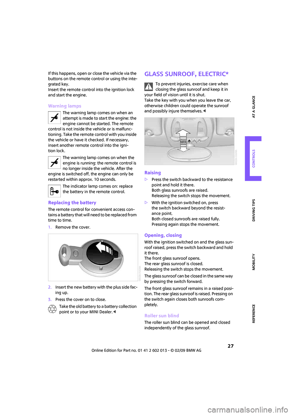
1.Remove the cover.
2.Insert the new battery with the plus side fac-
ing up.
3.Press the cover on to close.
Take the old battery to a battery collection
point or to your MINI Dealer.<
Glass sunroof, electric*
To prevent injuries, exercise care when
closing the glass sunroof and keep it in
your field of vision until it is shut.
Take the key with you when you leave the car,
otherwise children could operate the sunroof
and possibly injure themselves.<
Raising
>Press the switch backward to the resistance
point and hold it there.
Both glass sunroofs are raised.
Releasing the switch stops the movement.
>With the ignition switched on, press
the switch backward beyond the resist-
ance point.
Both closed sunroofs are raised fully.
Pressing again stops the movement.
Opening, closing
With the ignition switched on and the glass sun-
roof raised, press the switch backward and hold
it there.
The front glass sunroof opens.
The rear glass sunroof is closed.
Releasing the switch stops the movement.
The glass sunroof can be closed in the same way
by pressing the switch forward.
The front glass sunroof remains in a raised posi-
tion. The rear glass sunroof is raised. Pressing on
the switch again closes both sunroofs com-
pletely.
Roller sun blind
The roller sun blind can be opened and closed
independently of the glass sunroof.
Page 48 of 158
Everything under control
46
Everything under control
Odometer, outside
temperature display,
clock
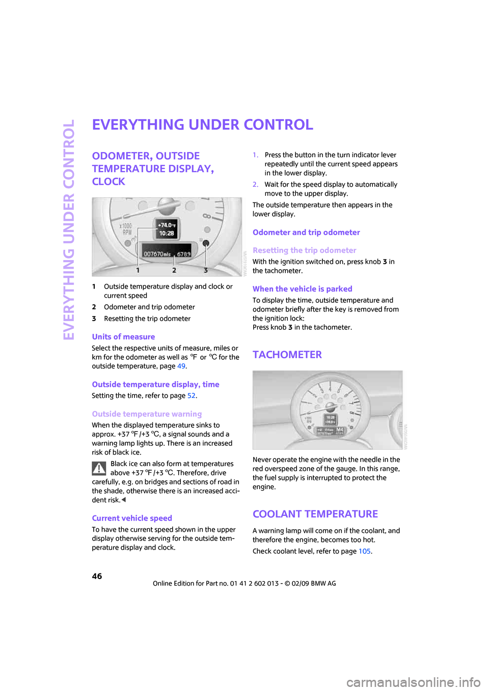
1Outside temperature display and clock or
current speed
2Odometer and trip odometer
3Resetting the trip odometer
Units of measure
Select the respective units of measure, miles or
km for the odometer as well as 7 or 6 for the
outside temperature, page49.
Outside temperature display, time
Setting the time, refer to page52.
Outside temperature warning
When the displayed temperature sinks to
approx. +377/+36, a signal sounds and a
warning lamp lights up. There is an increased
risk of black ice.
Black ice can also form at temperatures
above +377/+36. Therefore, drive
carefully, e.g. on bridges and sections of road in
the shade, otherwise there is an increased acci-
dent risk.<
Current vehicle speed
To have the current speed shown in the upper
display otherwise serving for the outside tem-
perature display and clock.1.Press the button in the turn indicator lever
repeatedly until the current speed appears
in the lower display.
2.Wait for the speed display to automatically
move to the upper display.
The outside temperature then appears in the
lower display.
Odometer and trip odometer
Resetting the trip odometer
With the ignition switched on, press knob 3 in
the tachometer.
When the vehicle is parked
To display the time, outside temperature and
odometer briefly after the key is removed from
the ignition lock:
Press knob 3 in the tachometer.
Tachometer
Never operate the engine with the needle in the
red overspeed zone of the gauge. In this range,
the fuel supply is interrupted to protect the
engine.
Coolant temperature
A warning lamp will come on if the coolant, and
therefore the engine, becomes too hot.
Check coolant level, refer to page105.
Page 50 of 158
Everything under control
48
Current fuel consumption
Displays the current fuel consumption to allow
you to see whether your current driving style is
conducive to fuel economy with minimum
exhaust emissions.
Average speed
Periods with the vehicle parked and the engine
switched off are not included in the calculations
of average speed.
To reset average speed: press the button in the
turn indicator lever for approx. 2 seconds.
Current vehicle speed
To have the current speed shown in the upper
display otherwise serving for the outside tem-
perature display and clock.
1.Press the button in the turn indicator lever
repeatedly until the current speed appears
in the lower display.
2.Wait for the speed display to automatically
move to the upper display.
The outside temperature then appears in the
lower display of the computer.
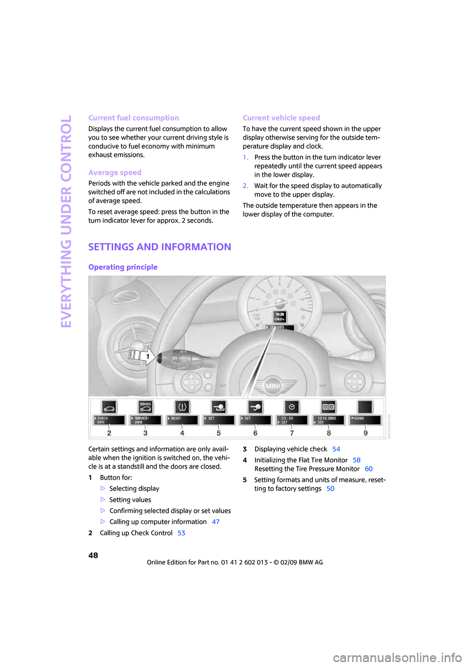
Settings and information
Operating principle
Certain settings and information are only avail-
able when the ignition is switched on, the vehi-
cle is at a standstill and the doors are closed.
1Button for:
>Selecting display
>Setting values
>Confirming selected display or set values
>Calling up computer information47
2Calling up Check Control533Displaying vehicle check54
4Initializing the Flat Tire Monitor58
Resetting the Tire Pressure Monitor60
5Setting formats and units of measure, reset-
ting to factory settings50
Page 53 of 158
REFERENCEAT A GLANCE CONTROLS DRIVING TIPS MOBILITY
51
Service requirements
The remaining driving distance and the date of
the next scheduled service are briefly displayed
immediately after you start the engine or switch
on the ignition.
The extent of service work required can be
read out from the remote control by your
MINI Dealer.<
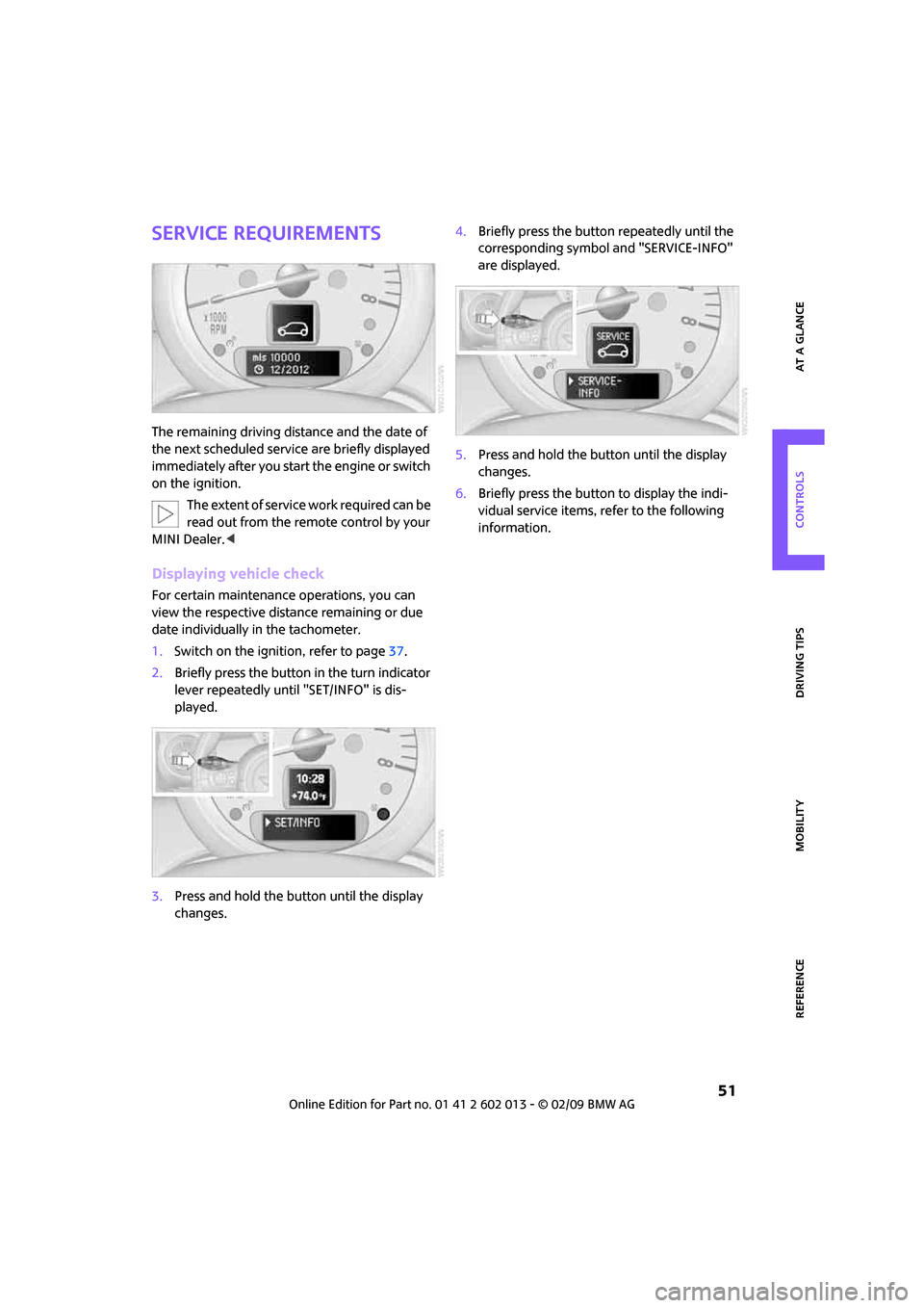
Displaying vehicle check
For certain maintenance operations, you can
view the respective distance remaining or due
date individually in the tachometer.
1.Switch on the ignition, refer to page37.
2.Briefly press the button in the turn indicator
lever repeatedly until "SET/INFO" is dis-
played.
3.Press and hold the button until the display
changes.4.Briefly press the button repeatedly until the
corresponding symbol and "SERVICE-INFO"
are displayed.
5.Press and hold the button until the display
changes.
6.Briefly press the button to display the indi-
vidual service items, refer to the following
information.
Page 54 of 158
Everything under control
52
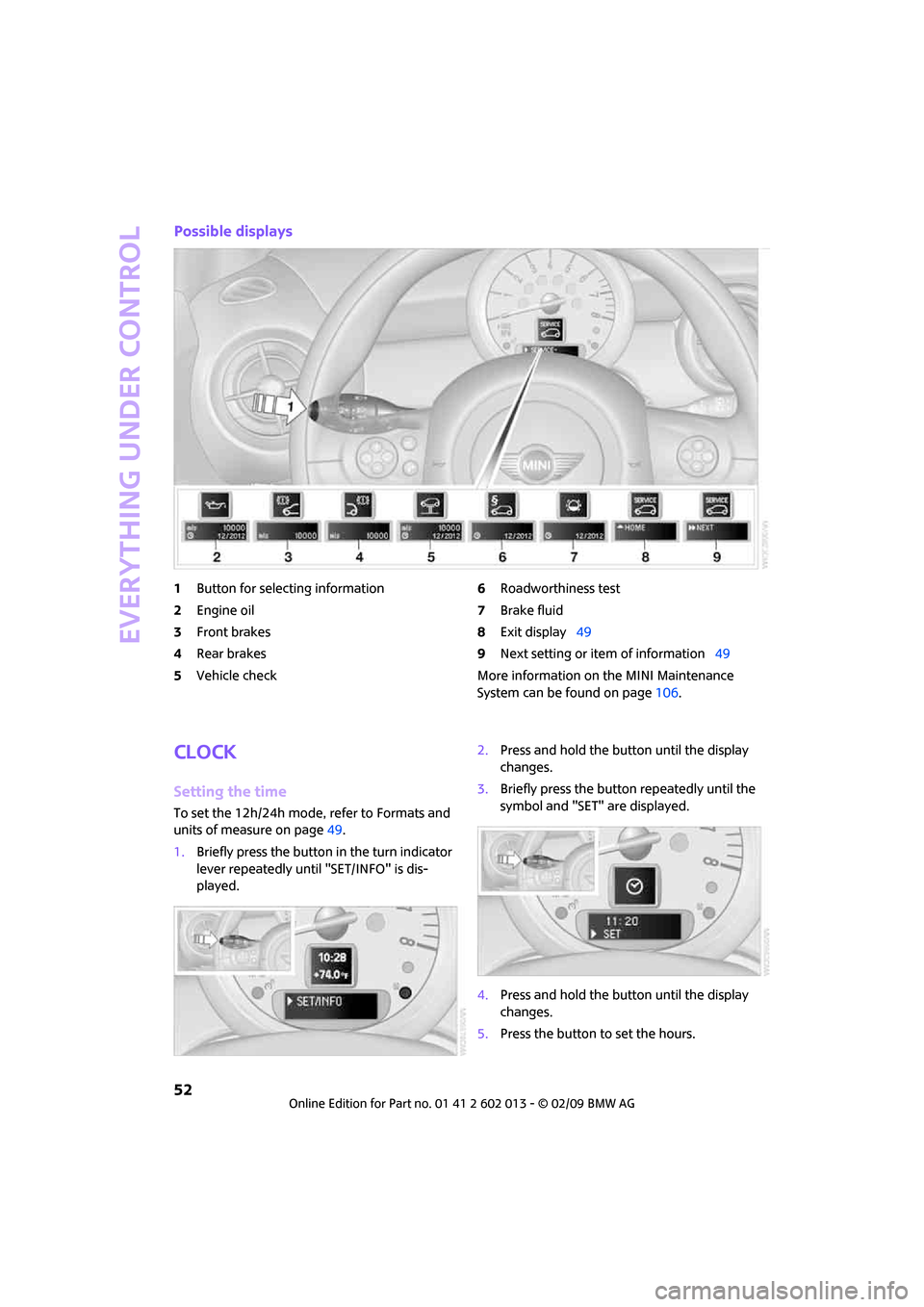
Possible displays
1Button for selecting information
2Engine oil
3Front brakes
4Rear brakes
5Vehicle check6Roadworthiness test
7Brake fluid
8Exit display49
9Next setting or item of information49
More information on the MINI Maintenance
System can be found on page106.
Clock
Setting the time
To set the 12h/24h mode, refer to Formats and
units of measure on page49.
1.Briefly press the button in the turn indicator
lever repeatedly until "SET/INFO" is dis-
played.2.Press and hold the button until the display
changes.
3.Briefly press the button repeatedly until the
symbol and "SET" are displayed.
4.Press and hold the button until the display
changes.
5.Press the button to set the hours.
Page 57 of 158
REFERENCEAT A GLANCE CONTROLS DRIVING TIPS MOBILITY
55
Technology for driving comfort
and safety
Park Distance
Control PDC*
The concept
PDC assists you with parking backwards. Acous-
tic signals warn you of the presence of an object
behind the vehicle. To measure the distance,
there are four ultrasonic sensors in either
bumper.
However, an acoustic warning does not sound
until an object is approx. 24 in/60 cm from the
corner sensors, or approx. 5 ft/1.50 m from the
center sensors.
. PDC is a parking aid that can indicate
objects when they are approached slowly,
as is usually the case when parking. Avoid
approaching an object at high speed, otherwise
physical circumstances
may lead to the system warning being issued
too late.<
Automatic mode
With the engine running or the ignition switched
on, the system is activated automatically after
approx. 1 second when you engage reverse gear
or move the automatic transmission selector
lever to position R. Wait this short period before
driving.
Acoustic signals
As the distance between vehicle and object
decreases, the intervals between the tones
become shorter. If the distance to the nearest
object falls to below roughly 1 ft/30 cm, then a
continuous tone sounds.
If the distance remains constant, e.g. when driv-
ing parallel to a wall, the acoustic signal stops
after approx. 3 seconds.
Adjustments
The volume of the acoustic signals can be
adjusted, refer to the Owner's Manual for Radio.
Malfunction
Indicator lamp comes on: PDC is mal-
functioning. Have the system checked.
To avoid this problem, keep the sensors
clean and free of ice or snow in order to ensure
that they will continue to operate effectively.
When using a high-pressure cleaner, do not
direct the jet toward the sensors for lengthy
periods and only spray from a distance of at least
4in/10cm.
System limitations
Even with PDC, final responsibility for esti-
mating the distance between the vehicle
and any obstructions always remains with the
driver. Sensors, too, have blind spots in which
objects cannot be detected. Moreover, ultra-
sonic detection can reach its physical limits with
objects such as trailer tow bars and couplings,
thin and wedge-shaped objects, etc. Low
objects already indicated, such as curbs, may
enter the sensors' blind spots before or after a
continuous audible signal is given. Higher, pro-
truding objects, such as wall ledges, may not be
detectable. Therefore, always drive cautiously,
otherwise there is a risk of personal injury or
property damage. Loud sound sources outside
or inside the car can drown out the PDC signal.<
Driving stability
control systems
Your MINI has a number of systems that help to
maintain the vehicle's stability even in adverse
driving conditions.
The laws of physics cannot be repealed,
even with driving stability control systems.
Page 62 of 158
Technology for driving comfort and safety
60
Tire Pressure
Monitor TPM*
The concept
TPM checks the inflation pressures of the four
mounted tires. The system notifies you if there is
a significant loss of pressure in one or more tires.
Functional requirement
In order to assure the reliable reporting of a flat
tire, the system must be reset while all tire infla-
tion pressures are correct.
Always use wheels with TPM electronics. Other-
wise, the system may malfunction.
Each time a tire inflation pressure has
been corrected or a wheel or tire has been
changed, reset the system.<
System limitations
TPM cannot warn you in advance of sud-
den severe tire damage caused by outside
influences.<
The system does not work correctly if it has not
been reset; for example, a flat tire may be indi-
cated even though the tire inflation pressures
are correct.
The system is inactive and cannot indicate a flat
tire if a wheel without TPM electronics, such as a
compact spare wheel
*, has been mounted, or if
TPM is temporarily malfunctioning due to other
systems or devices using the same radio fre-
quency.
Resetting the system
Each time a tire inflation pressure has
been corrected or a wheel or tire has been
changed, reset the system.<
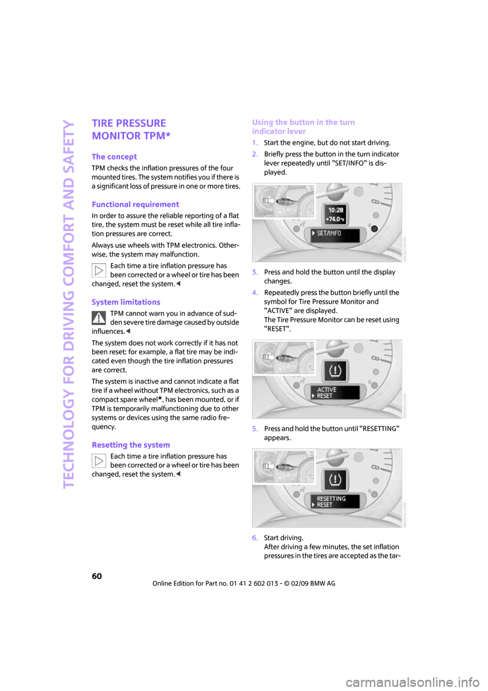
Using the button in the turn
indicator lever
1.Start the engine, but do not start driving.
2.Briefly press the button in the turn indicator
lever repeatedly until "SET/INFO" is dis-
played.
3.Press and hold the button until the display
changes.
4.Repeatedly press the button briefly until the
symbol for Tire Pressure Monitor and
"ACTIVE" are displayed.
The Tire Pressure Monitor can be reset using
"RESET".
5.Press and hold the button until "RESETTING"
appears.
6.Start driving.
After driving a few minutes, the set inflation
pressures in the tires are accepted as the tar-
Page 78 of 158
Practical interior accessories
76
The corresponding memory button 1 is now
programmed with the signal of the original
hand-held transmitter.
You can operate the system with the engine
running or with the ignition switched on.
If the system fails to function even after
repeated programming, check whether
the original hand-held transmitter uses an alter-
nating-code system. To do so, either read the
instructions for the original hand-held transmit-
ter or hold down the programmed memory
button1 of the integrated universal remote con-
trol. If the LED2 on the integrated universal
remote control flashes rapidly and then remains
lit for about two seconds, the original hand-held
transmitter uses an alternating-code system. If it
uses an alternating-code system, program the
memory buttons1 as described under Alternat-
ing-code hand-held transmitters.<
Alternating-code hand-held
transmitters
To program the integrated universal remote
control, consult the operating instructions for
the device to be set. You will find information
there on the possibilities for synchronization
or programming of additional hand-held trans-
mitters.
When programming hand-held transmitters that
employ an alternating code, please observe the
following supplementary instructions:
Programming will be easier with the aid of
a second person.<
1.Park your vehicle within the range of the re-
mote-controlled device.
2.Program the integrated universal remote
control as described above in the section
Fixed-code hand-held transmitters.
3.Locate the button on the receiver of the
device to be set, e.g. on the drive unit.
4.Press the button on the receiver of the
device to be set. After step 4, you have
approx. 30 seconds for the next step 5.
5.Press the programmed memory button1 of
the integrated universal remote control
three times.The corresponding memory button 1 is now
programmed with the signal of the original
hand-held transmitter.
Clearing stored programs
Press both outer memory buttons1 for approx.
20 seconds until the LED2 flashes: All stored
programs are cleared.
It is not possible to clear individual programs.
Reassigning individual programs
1.Hold the original hand-held transmitter at a
distance of approx. 2 to 12 in/5 to 30 cm
from the memory buttons1.
The required distance between the
hand-held transmitter and the mem-
ory buttons1 depends on the system of
the respective original hand-held transmit-
ter used.<
2.Press the desired memory button1 of the
integrated universal remote control.
3.If the LED 2 flashes slowly after approx.
20 seconds, press the transmit key of the
original hand-held transmitter and release
both buttons as soon as the LED2 flashes
rapidly.
If the LED 2 does not flash rapidly after
approx. 15 seconds, alter the distance and
repeat this step.
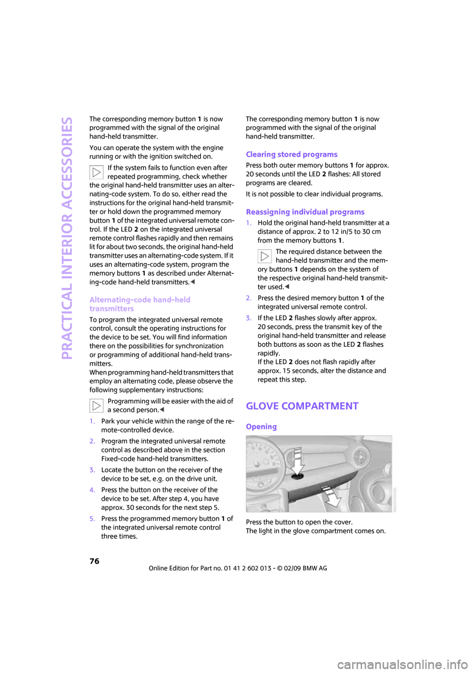
Glove compartment
Opening
Press the button to open the cover.
The light in the glove compartment comes on.