warning light MINI Clubman 2011 Owner's Manual (Mini Connected)
[x] Cancel search | Manufacturer: MINI, Model Year: 2011, Model line: Clubman, Model: MINI Clubman 2011Pages: 256, PDF Size: 3.75 MB
Page 14 of 256
AT A GLANCECockpit
12
Displays
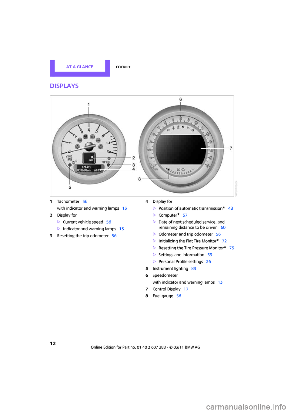
1Tachometer 56
with indicator and warning lamps 13
2 Display for
>Current vehicle speed 56
> Indicator and warning lamps 13
3 Resetting the trip odometer 564
Display for
>Position of automatic transmission
*48
> Computer
*57
> Date of next scheduled service, and
remaining distance to be driven 60
> Odometer and trip odometer 56
> Initializing the Flat Tire Monitor
*72
> Resetting the Tire Pressure Monitor
*75
> Settings and information 59
> Personal Prof ile settings26
5 Instrument lighting 83
6 Speedometer
with indicator and warning lamps 13
7 Control Display 17
8 Fuel gauge 56
Page 15 of 256
CockpitAT A GLANCE
13
Indicator and warning
lamps
The concept
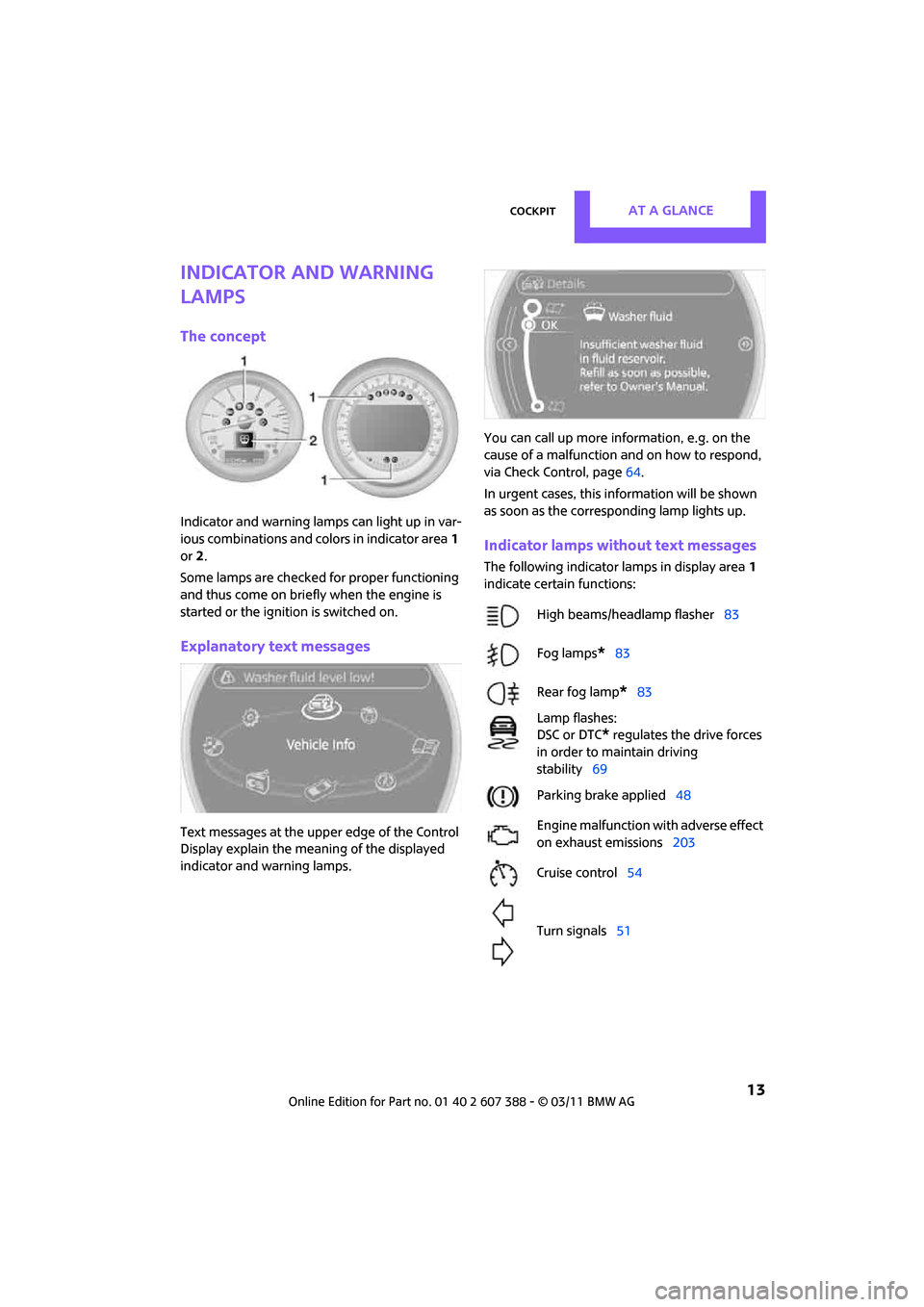
Indicator and warning lamps can light up in var-
ious combinations and colors in indicator area1
or 2.
Some lamps are checked for proper functioning
and thus come on briefly when the engine is
started or the ignition is switched on.
Explanatory text messages
Text messages at the uppe r edge of the Control
Display explain the mean ing of the displayed
indicator and warning lamps. You can call up more information, e.g. on the
cause of a malfunction and on how to respond,
via Check Control, page
64.
In urgent cases, this information will be shown
as soon as the corresponding lamp lights up.
Indicator lamps without text messages
The following indicator lamps in display area 1
indicate certain functions:
High beams/headlamp flasher 83
Fog lamps
*83
Rear fog lamp
*83
Lamp flashes:
DSC or DTC
* regulates the drive forces
in order to maintain driving
stability 69
Parking brake applied 48
Engine malfunction with adverse effect
on exhaust emissions 203
Cruise control 54
Turn signals 51
Page 17 of 256
CockpitAT A GLANCE
15
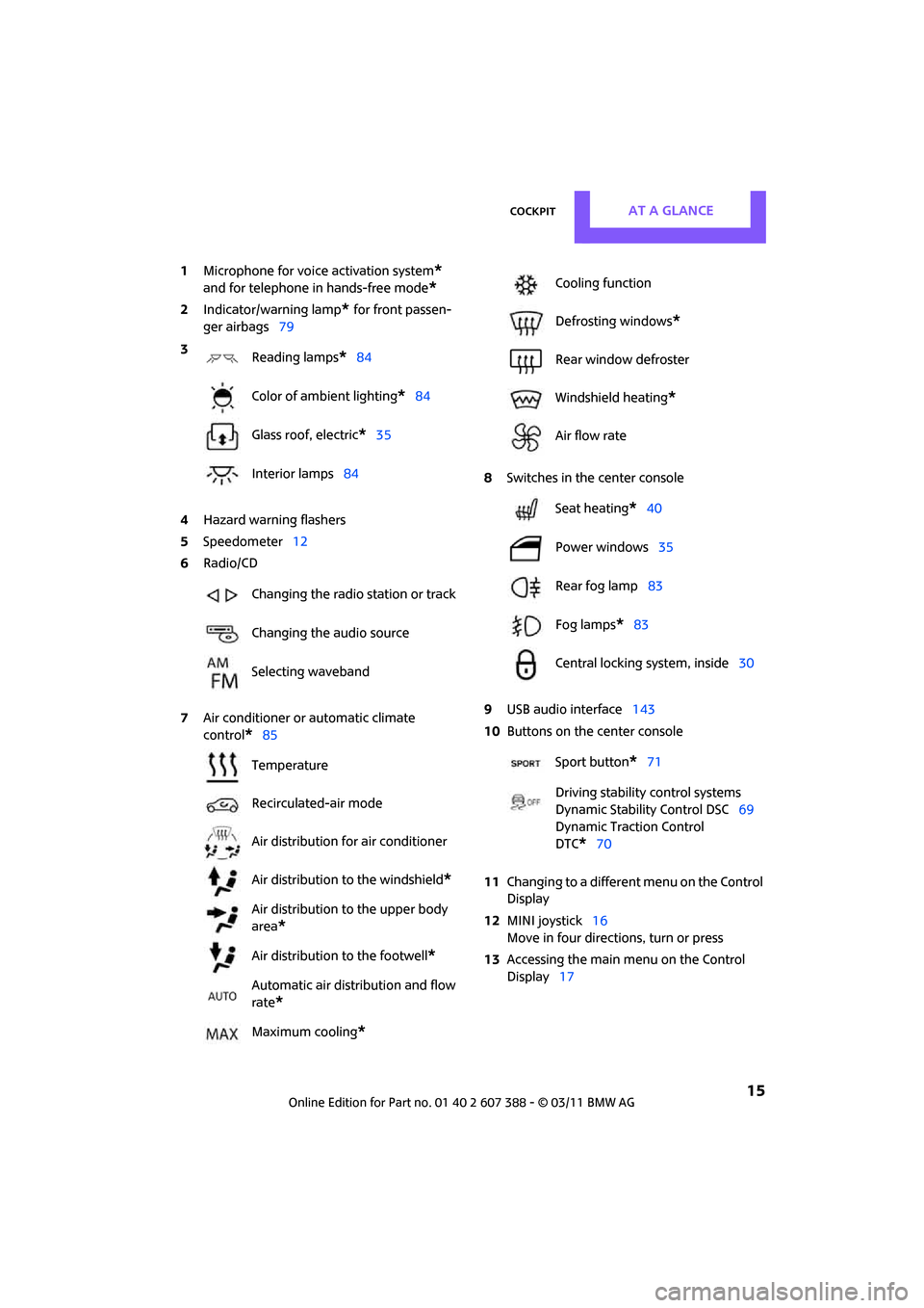
1Microphone for voice activation system*
and for telephone in hands-free mode*
2Indicator/warning lamp* for front passen-
ger airbags 79
4 Hazard warning flashers
5 Speedometer 12
6 Radio/CD
7 Air conditioner or automatic climate
control
*85 8
Switches in the center console
9 USB audio interface 143
10 Buttons on the center console
11 Changing to a differen t menu on the Control
Display
12 MINI joystick 16
Move in four directions, turn or press
13 Accessing the main me nu on the Control
Display 17
3
Reading lamps
*84
Color of ambient lighting
*84
Glass roof, electric
*35
Interior lamps 84
Changing the radio station or track
Changing the audio source
Selecting waveband
Temperature
Recirculated-air mode
Air distribution for air conditioner
Air distribution to the windshield
*
Air distribution to the upper body
area
*
Air distribution to the footwell*
Automatic air distribution and flow
rate
*
Maximum cooling*
Cooling function
Defrosting windows
*
Rear window defroster
Windshield heating
*
Air flow rate
Seat heating
*40
Power windows 35
Rear fog lamp 83
Fog lamps
*83
Central locking system, inside 30
Sport button
*71
Driving stability control systems
Dynamic Stability Control DSC 69
Dynamic Traction Control
DTC*70
Page 29 of 256
Opening and closingCONTROLS
27
>Triple turn signal activation 51
> Settings for the displa ys on the on-board
computer, in the speedometer and in the
tachometer:
> 12 h/24 h mode of the clock 63
> Date format 63
> Brightness of the Control Display 67
> Language on the Control Display 66
> Units of measure for fuel consumption,
distance covered/re maining distances
and temperature 60
> Show visual warning for Park Distance Con-
trol PDC
*68
> Light settings:
>Pathway lighting 81
> Daytime running lights 82
> Automatic climate control: activating/deac-
tivating the AUTO program, setting the tem-
perature, air volume and air distribution 87
> Entertainment:
>Tone control 131
> Adjusting vo lume levels 130
Central lock ing system
The concept
The central locking system is ready for operation
whenever the driver's door is closed.
The system simultaneously engages and
releases the locks on the following:
>Doors
> Split Rear Barn Doors
> Fuel filler flap
Operating from outside
>Via the remote control
> Via the door lock
*
>In cars with Comfort Access*, via the door
handles on the driver's and passenger's
sides
The anti-theft system is also operated at the
same time. It prevents the doors from being
unlocked using the lock buttons or door han-
dles. The remote control can also be used to
switch on/off the welcome lamps and interior
lamps. The alarm system
* is also activated or
deactivated, page 31.
Operating from inside
Button for central locking system, page 30.
In the event of a sufficiently severe accident, the
central locking system unlocks automatically. In
addition, the hazard warning flashers and inte-
rior lamps come on.
Opening and closing:
from outside
Persons or animals in a parked vehicle
could lock the doors from the inside. Take
the key with you when you leave the vehicle so
that the vehicle can be opened from the out-
side. <
Using the remote control
Unlocking
Press the button.
The welcome lamps and interior lamps come on.
Unlocking mode
You can also set which parts of the car are
unlocked. The setting is stored for the remote
control in use.
Page 36 of 256
CONTROLSOpening and closing
34
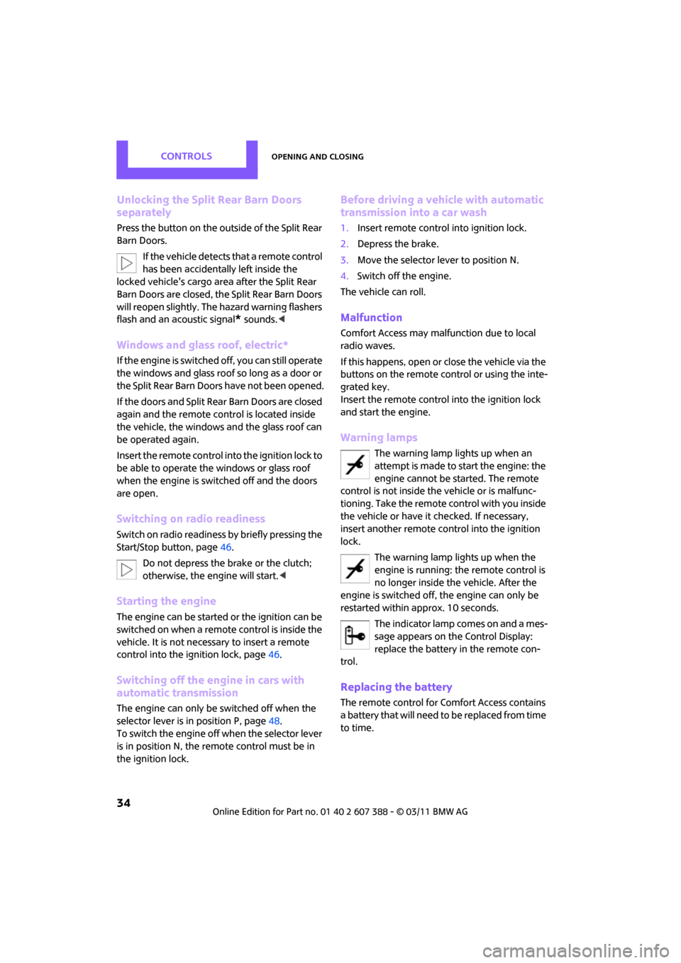
Unlocking the Split Rear Barn Doors
separately
Press the button on the outside of the Split Rear
Barn Doors.If the vehicle detects that a remote control
has been accidentally left inside the
locked vehicle's cargo area after the Split Rear
Barn Doors are closed, the Split Rear Barn Doors
will reopen slightly. The hazard warning flashers
flash and an acoustic signal
* sounds. <
Windows and glass roof, electric*
If the engine is switched off, you can still operate
the windows and glass roof so long as a door or
the Split Rear Barn Doors have not been opened.
If the doors and Split Rear Barn Doors are closed
again and the remote cont rol is located inside
the vehicle, the windows and the glass roof can
be operated again.
Insert the remote control into the ignition lock to
be able to operate the windows or glass roof
when the engine is switched off and the doors
are open.
Switching on radio readiness
Switch on radio readiness by briefly pressing the
Start/Stop button, page 46.
Do not depress the brake or the clutch;
otherwise, the engine will start. <
Starting the engine
The engine can be started or the ignition can be
switched on when a remote control is inside the
vehicle. It is not necessary to insert a remote
control into the ignition lock, page 46.
Switching off the engine in cars with
automatic transmission
The engine can only be switched off when the
selector lever is in position P, page 48.
To switch the engine off when the selector lever
is in position N, the remote control must be in
the ignition lock.
Before driving a vehicle with automatic
transmission into a car wash
1. Insert remote control into ignition lock.
2. Depress the brake.
3. Move the selector le ver to position N.
4. Switch off the engine.
The vehicle can roll.
Malfunction
Comfort Access may malf unction due to local
radio waves.
If this happens, open or close the vehicle via the
buttons on the remote control or using the inte-
grated key.
Insert the remote control into the ignition lock
and start the engine.
Warning lamps
The warning lamp lights up when an
attempt is made to start the engine: the
engine cannot be started. The remote
control is not inside the vehicle or is malfunc-
tioning. Take the remote control with you inside
the vehicle or have it checked. If necessary,
insert another remote co ntrol into the ignition
lock.
The warning lamp lights up when the
engine is running: the remote control is
no longer inside the vehicle. After the
engine is switched off, the engine can only be
restarted within approx. 10 seconds.
The indicator lamp comes on and a mes-
sage appears on the Control Display:
replace the battery in the remote con-
trol.
Replacing the battery
The remote control for Comfort Access contains
a b a t t e r y t h a t w i l l n e e d t o b e r e p l a c e d f r o m t i m e
to time.
Page 57 of 256

DrivingCONTROLS
55
Display in tachometer*
Selected speed is displayed briefly.If --- mph or --- km/h is displayed briefly in
the tachometer, the conditions necessary
for operation may not be fulfilled.<
Malfunction
The warning lamp in the tachometer
lights up if the system fails. A message
appears on the Control Display.
Page 59 of 256
Controls overviewCONTROLS
57
If the range displayed is less than
30 miles/50 km, be sure to refuel; other-
wise, engine functions are not guaranteed and
damage could occur. <
With a dynamic driving st yle, e.g. rapid corner-
ing, engine functions are not always assured.
Computer*
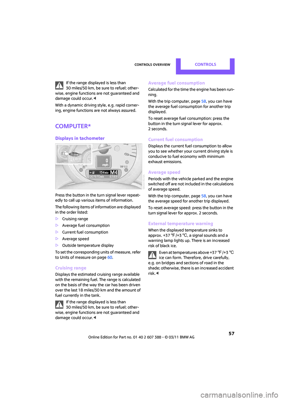
Displays in tachometer
Press the button in the turn signal lever repeat-
edly to call up various items of information.
The following items of information are displayed
in the order listed:
> Cruising range
> Average fuel consumption
> Current fuel consumption
> Average speed
> Outside temperature display
To set the corresponding units of measure, refer
to Units of measure on page 60.
Cruising range
Displays the estimated cruising range available
with the remaining fuel. The range is calculated
on the basis of the way the car has been driven
over the last 18 miles/30 km and the amount of
fuel currently in the tank.
If the range displayed is less than
30 miles/50 km, be sure to refuel; other-
wise, engine functions are not guaranteed and
damage could occur. <
Average fuel consumption
Calculated for the time the engine has been run-
ning.
With the trip computer, page 58, you can have
the average fuel consumption for another trip
displayed.
To reset average fuel consumption: press the
button in the turn signal lever for approx.
2 seconds.
Current fuel consumption
Displays the current fuel consumption to allow
you to see whether your current driving style is
conducive to fuel economy with minimum
exhaust emissions.
Average speed
Periods with the vehicle parked and the engine
switched off are not includ ed in the calculations
of average speed.
With the trip computer, page 58, you can have
the average speed for another trip displayed.
To reset average speed: press the button in the
turn signal lever for approx. 2 seconds.
External temperature warning
When the displayed temperature sinks to
approx. +37 7/+3 6, a signal sounds and a
warning lamp lights up. There is an increased
risk of black ice.
Even at temperatures above +37 7/+3 6
ice can form. Therefore, drive carefully,
e.g. on bridges and sections of road in the
shade; otherwise, there is an increased accident
risk. <
Page 66 of 256
CONTROLSControls overview
64
Check Control
The concept
The Check Control monitors vehicle functions
and alerts you to any malfunctions in the sys-
tems monitored. Check Control messages
involve indicator and warning lamps in the dis-
play and, in some circumstances, an acoustic
signal as well as text messages at the bottom of
the Control Display.
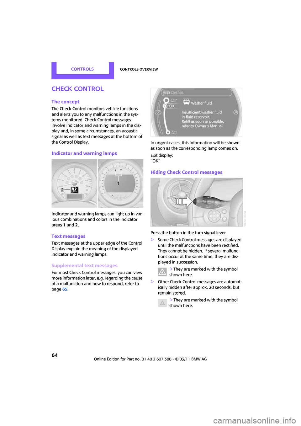
Indicator and warning lamps
Indicator and warning lamps can light up in var-
ious combinations and colors in the indicator
areas 1 and 2.
Text messages
Text messages at the uppe r edge of the Control
Display explain the mean ing of the displayed
indicator and warning lamps.
Supplemental text messages
For most Check Control messages, you can view
more information later, e.g. regarding the cause
of a malfunction and how to respond, refer to
page 65. In urgent cases, this information will be shown
as soon as the corresponding lamp comes on.
Exit display:
"OK"
Hiding Check Control messages
Press the button in th
e turn signal lever.
> Some Check Control messages are displayed
until the malfunctions have been rectified.
They cannot be hidden. If several malfunc-
tions occur at the same time, they are dis-
played in succession.
>They are marked with the symbol
shown here.
> Other Check Control messages are automat-
ically hidden after approx. 20 seconds, but
remain stored.
>They are marked with the symbol
shown here.
Page 70 of 256
CONTROLSTechnology for driving comfort and safety
68
Technology for driving comfort and
safety
Park Distance Control
PDC*
The concept
PDC assists you with parking in reverse. Acoustic
signals and a visual indicator
warn you of the
presence of an object behind the vehicle. To
measure the distance, there are four ultrasonic
sensors in either bumper.
These sensors have a range of approx.
6.5 ft/2 m. However, an acoustic warning
does not sound until an object is approx. 24 in/
60 cm from the rear corner sensors, or approx.
5 ft/1.50 m from the rear center sensors. PDC is
a parking aid that can indicate objects when
they are approached slowly, as is usually the
case when parking. Avoid approaching an
object at high speed; ot herwise, physical cir-
cumstances may lead to the system warning
being issued too late. <
Automatic mode
With the engine running or the ignition switched
on, the system is activated automatically after
approx. 1 second when you engage reverse
gear or move the automatic transmission selec-
tor lever to position R. Wait this short period
before driving.
Acoustic signals
As the distance between vehicle and object
decreases, the intervals between the tones
become shorter. If the distance to the nearest
object falls to below roughly 1 ft/30 cm, then a
continuous tone sounds.
If the distance remains co nstant, e.g. when driv-
ing parallel to a wall, th e acoustic signal stops
after approx. 3 seconds.
Malfunction
Indicator lamp lights up: PDC has failed.
A message appears on the Control Dis-
play. Have the system checked.
To avoid this problem, keep the sensors clean
and free of ice or snow in order to ensure that
they will continue to operate effectively. When
using a high-pressure cleaner, do not direct the
jet toward the sensors for lengthy periods and
only spray from a distance of at least 4 in/10 cm.
PDC with visual warning
To have the system show distances to objects on
the Control Display. The contours of distant
objects are shown on the Control Display even
before the acoustic sign al sounds. The display
appears on the Control Display as soon as the
transmission is shifted into reverse or the selec-
tor lever is moved into the R position.
System limitations
Even with PDC, final responsibility for esti-
mating the distance between the vehicle
and any obstructions always remains with the
driver. Sensors, too, have blind spots in which
objects cannot be dete cted. Moreover, ultra-
sonic detection can reach its physical limits with
objects such as trailer tow bars and couplings,
thin and wedge-shaped objects, etc. Low
objects already indicated, such as curbs, may
enter the sensors' blind spots before or after a
continuous audible signal is given. Higher, pro-
truding objects, such as wall ledges, may not be
detectable. Therefore, always drive cautiously;
otherwise, there is a risk of personal injury or
property damage. Loud sound sources outside
or inside the car can drown out the PDC signal. <
Page 78 of 256
CONTROLSTechnology for driving comfort and safety
76
If the inflation pressure is correct in all four
tires, then the Tire Pressure Monitor may not
have been reset. The system must then be
reset.
If it is not possible to identify the damaged
tire, contact your MINI dealer.
2. Use the Mobility System to remedy the flat
tire on the damaged wheel, refer to
page 213, or to replace the damaged wheel,
refer to page. 215.
The use of tire sealant, e.g. Mobility System,
can damage the TPM wheel electronics. In
this case, have the el ectronics checked and
replaced if necessary at your earliest oppor-
tunity.
Run-flat tires*
You can continue driving with a damaged tire at
speeds up to 50 mph/80 km/h.
If the vehicle is not equipped with run-flat
tires, do not continue driving; continuing
to drive can result in serious accidents. <
Continued driving with a flat tire
When driving with a damaged tire:
1.Avoid sudden braking and steering maneu-
vers.
2. Do not exceed a speed of 50 mph/80 km/h.
3. At the next opportunity, check the air pres-
sure in all four tires.
If the inflation pressure is correct in all four
tires, then the Tire Pressure Monitor may not
have been reset. The system must then be
reset.
Possible driving distance with complete loss of
tire inflation pressure:
The distance it is possible to drive with a flat tire
depends on the load and the stress on the vehi-
cle while driving.
With an average load, it may be possible to drive
for approx. 50 miles/80 km.
When driving with damaged tires, the handling
characteristics change, e.g. the vehicle will skid sooner when braking, braking distances will be
longer, or self-steerin
g response will change.
Adapt your driving style accordingly. Avoid turn-
ing abruptly and driving over obstacles such as
curbs, potholes, etc.
Since the possible driving distance depends to a
considerable degree on the strain exerted on
the vehicle while driving, it can be shorter or,
with a gentle driving styl e, can also be longer,
depending on the speed, road condition, exter-
nal temperature, vehicle load, etc.
Drive cautiously and do not exceed a
speed of 50 mph/80 km/h.
A loss of tire inflation pressure results in a
change in the handling characteristics, e.g.
reduced lane stability during braking, a longer
braking distance and alte red self-steering prop-
erties. <
Vibrations or loud no ises while driving can
indicate complete failure of the tire.
Reduce your speed and bring the vehicle to a
stop; otherwise, pieces of tire may come off,
which could result in an accident. Do not con-
tinue driving and contac t your MINI dealer.
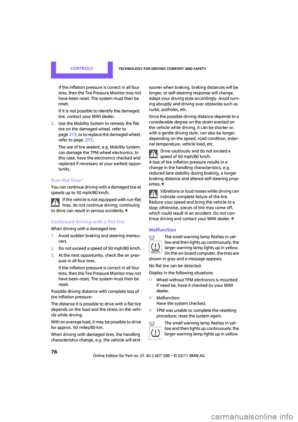
low and then lights up continuously; the
larger warning lamp lights up in yellow.
On the on-board computer, the tires are
shown in gray and a message appears.
No flat tire can be detected.
Display in the following situations:
> Wheel without TPM electronics is mounted:
If need be, have it checked by your MINI
dealer.
> Malfunction:
Have the system checked.
> TPM was unable to complete the resetting
procedure; reset the system again.
The small warning lamp flashes in yel-
low and then lights up continuously; the
larger warning lamp lights up in yellow.