warning light MINI COOPER 2015 Workshop Manual
[x] Cancel search | Manufacturer: MINI, Model Year: 2015, Model line: COOPER, Model: MINI COOPER 2015Pages: 248, PDF Size: 5.43 MB
Page 154 of 248
Compartments in the
doors
WARNING
Breakable object, for example glass bot‐
tle, can break in the event of an accident. Bro‐
ken glass can be scattered in the car's interior.
There is risk of injuries. Do not stow any break‐
able objects in the car's interior. ◀
Center armrest
The center armrest contains a storage compart‐
ment.
Opening
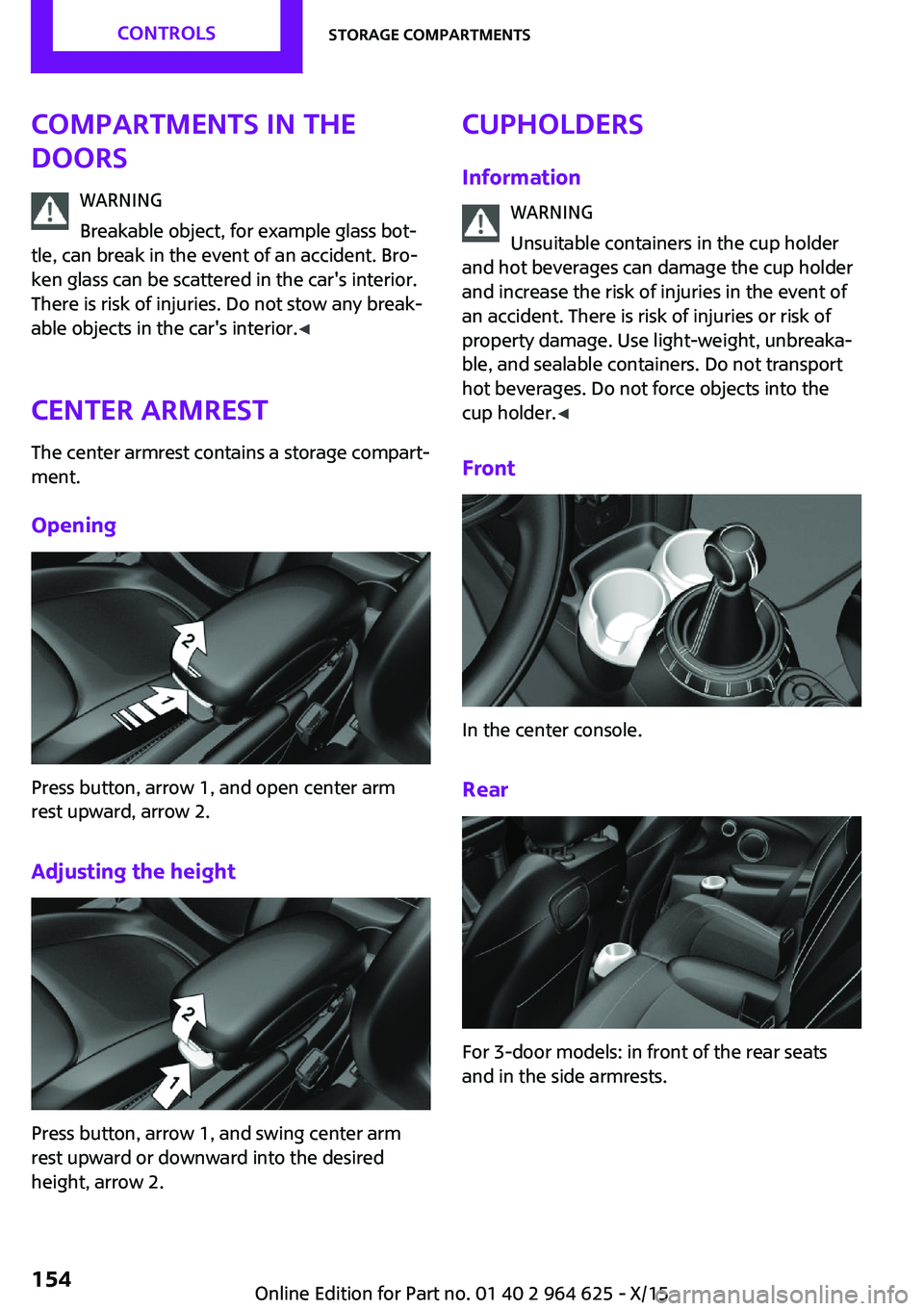
Press button, arrow 1, and open center arm
rest upward, arrow 2.
Adjusting the height
Press button, arrow 1, and swing center arm
rest upward or downward into the desired
height, arrow 2.
Cupholders
Information WARNING
Unsuitable containers in the cup holder
and hot beverages can damage the cup holder
and increase the risk of injuries in the event of
an accident. There is risk of injuries or risk of
property damage. Use light-weight, unbreaka‐
ble, and sealable containers. Do not transport
hot beverages. Do not force objects into the
cup holder. ◀
Front
In the center console.
Rear
For 3-door models: in front of the rear seats
and in the side armrests.
Seite 154CONTROLSStorage compartments154
Online Edition for Part no. 01 40 2 964 625 - X/15
Page 155 of 248
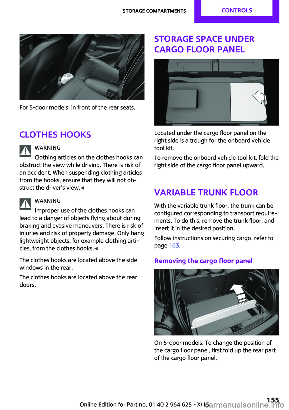
For 5-door models: in front of the rear seats.Clothes hooks WARNING
Clothing articles on the clothes hooks can
obstruct the view while driving. There is risk of
an accident. When suspending clothing articles
from the hooks, ensure that they will not ob‐
struct the driver's view. ◀
WARNING
Improper use of the clothes hooks can
lead to a danger of objects flying about during
braking and evasive maneuvers. There is risk of
injuries and risk of property damage. Only hang
lightweight objects, for example clothing arti‐
cles, from the clothes hooks. ◀
The clothes hooks are located above the side
windows in the rear.
The clothes hooks are located above the rear
doors.
Storage space under
cargo floor panel
Located under the cargo floor panel on the
right side is a trough for the onboard vehicle
tool kit.
To remove the onboard vehicle tool kit, fold the
right side of the cargo floor panel upward.
Variable trunk floor
With the variable trunk floor, the trunk can be
configured corresponding to transport require‐
ments. To do this, remove the trunk floor, and
insert it in the desired position.
Follow instructions on securing cargo, refer to
page 163.
Removing the cargo floor panel
On 5-door models: To change the position of
the cargo floor panel, first fold up the rear part
of the cargo floor panel.
Seite 155Storage compartmentsCONTROLS155
Online Edition for Part no. 01 40 2 964 625 - X/15
Page 156 of 248
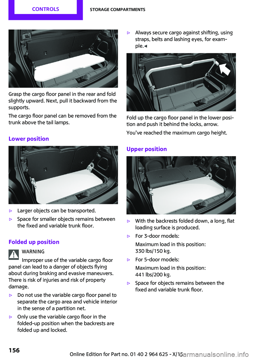
Grasp the cargo floor panel in the rear and fold
slightly upward. Next, pull it backward from the
supports.
The cargo floor panel can be removed from the
trunk above the tail lamps.
Lower position
▷Larger objects can be transported.▷Space for smaller objects remains between
the fixed and variable trunk floor.
Folded up position
WARNING
Improper use of the variable cargo floor
panel can lead to a danger of objects flying
about during braking and evasive maneuvers.
There is risk of injuries and risk of property
damage.
▷Do not use the variable cargo floor panel to
separate the cargo area and vehicle interior
in the sense of a partition net.▷Only use the variable cargo floor in the
folded-up position when the backrests are
folded up and locked.▷Always secure cargo against shifting, using
straps, belts and lashing eyes, for exam‐
ple. ◀
Fold up the cargo floor panel in the lower posi‐
tion and push it behind the locks, arrow.
You've reached the maximum cargo height.
Upper position
▷With the backrests folded down, a long, flat
loading surface is produced.▷For 3-door models:
Maximum load in this position:
330 lbs/150 kg.▷For 5-door models:
Maximum load in this position:
441 lbs/200 kg.▷Space for objects remains between the
fixed and variable trunk floor.Seite 156CONTROLSStorage compartments156
Online Edition for Part no. 01 40 2 964 625 - X/15
Page 162 of 248

Objects in the area around the pedalsWARNING
Objects in the driver's floor area can limit
the pedal distance or block a depressed pedal.
There is risk of an accident. Stow objects in the
vehicle such that they are secured and cannot
enter into the driver's floor area. Use floor mats
that are suitable for the vehicle and can be
safely attached to the floor. Do not use loose
floor mats and do not layer several floor mats.
Make sure that there is sufficient clearance for
the pedals. Ensure that the floor mats are se‐
curely fastened again after they were removed,
for example for cleaning. ◀
Driving in wet conditions When roads are wet, salted, or in heavy rain,
press brake pedal ever so gently every few
miles.
Ensure that this action does not endanger other
traffic.
The heat generated in this process helps dry
the brake discs and pads.
In this way braking efficiency will be available
when you need it.
Hills WARNING
Light but consistent brake pressure can
lead to high temperatures, brakes wearing out
and possibly even brake failure. There is risk of
an accident. Avoid placing excessive stress on
the brake system. ◀
WARNING
In idle or with the engine switched off,
safety-relevant functions are restricted or not
available anymore, for example braking effect
of the engine or braking force and steering
support. There is risk of an accident. Do not
drive in idle or with the engine switched off. ◀
Drive long or steep downhill gradients in the
gear that requires least braking efforts. Other‐wise the brakes may overheat and reduce
brake efficiency.
You can increase the engine's braking effect by
shifting down, going all the way to first gear, if
needed.
Brake disc corrosion Corrosion on the brake discs and contamina‐
tion on the brake pads are furthered by:▷Low mileage.▷Extended periods when the vehicle is not
used at all.▷Infrequent use of the brakes.
Corrosion will built up when the maximum
pressure applied to the brake pads during brak‐
ing is not reached - thus discs don't get
cleaned.
Corrosion buildup on the brake discs will cause
a pulsating effect on the brakes in their re‐
sponse - generally that cannot be corrected.
Condensation under the parked vehicle When using the automatic climate control, con‐
densation water develops collecting under‐
neath the vehicle.
Ground clearance CAUTION
If ground clearance is insufficient, there
might be contact with the front or rear spoiler
for example when driving over curbs or enter‐
ing into underground car parking garages.
There is risk of property damage. Ensure that
there is sufficient ground clearance available. ◀
Seite 162DRIVING TIPSThings to remember when driving162
Online Edition for Part no. 01 40 2 964 625 - X/15
Page 164 of 248
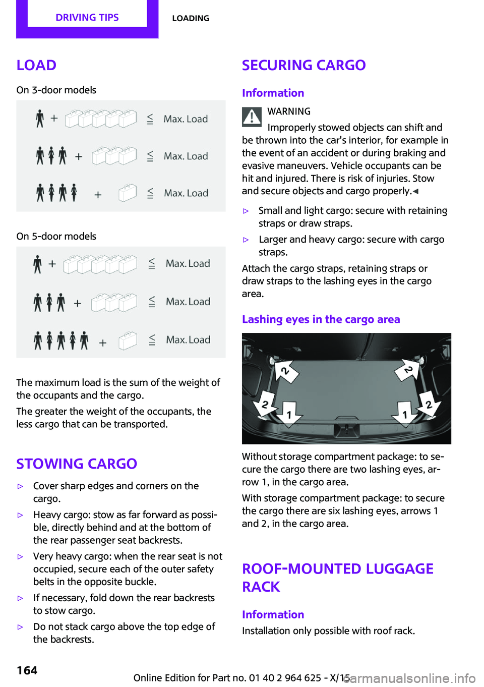
LoadOn 3-door modelsOn 5-door models
The maximum load is the sum of the weight of
the occupants and the cargo.
The greater the weight of the occupants, the
less cargo that can be transported.
Stowing cargo
▷Cover sharp edges and corners on the
cargo.▷Heavy cargo: stow as far forward as possi‐
ble, directly behind and at the bottom of
the rear passenger seat backrests.▷Very heavy cargo: when the rear seat is not
occupied, secure each of the outer safety
belts in the opposite buckle.▷If necessary, fold down the rear backrests
to stow cargo.▷Do not stack cargo above the top edge of
the backrests.Securing cargo
Information WARNING
Improperly stowed objects can shift and
be thrown into the car's interior, for example in
the event of an accident or during braking and
evasive maneuvers. Vehicle occupants can be
hit and injured. There is risk of injuries. Stow
and secure objects and cargo properly. ◀▷Small and light cargo: secure with retaining
straps or draw straps.▷Larger and heavy cargo: secure with cargo
straps.
Attach the cargo straps, retaining straps or
draw straps to the lashing eyes in the cargo
area.
Lashing eyes in the cargo area
Without storage compartment package: to se‐
cure the cargo there are two lashing eyes, ar‐
row 1, in the cargo area.
With storage compartment package: to secure
the cargo there are six lashing eyes, arrows 1
and 2, in the cargo area.
Roof-mounted luggage
rack
Information Installation only possible with roof rack.
Seite 164DRIVING TIPSLoading164
Online Edition for Part no. 01 40 2 964 625 - X/15
Page 168 of 248

The Coasting driving condition is enabled under
certain conditions.
Under certain conditions the engine is auto‐
matically decoupled from the transmission in
selector lever position D. The vehicle continues
traveling with the engine idling to reduce fuel
consumption. Selector lever position D remains
engaged. An indicator provides information
about the distance traveled in Coasting mode.
In addition, context-sensitive instructions are
displayed to assist with an optimized fuel con‐
sumption driving style.
The achieved extended range is displayed in
the instrument cluster.
Overview The system includes the following MINIMAL
functions and displays:▷GREEN bonus range, refer to page 169.▷GREEN tips driving instruction, refer to
page 169.▷GREEN climate control, refer to page 168.▷MINIMALISM analyzer, refer to page 171.▷Coasting driving condition, refer to
page 170.
Activating GREEN Mode
Turn Driving Dynamics Control to
the right until GREEN Mode is
displayed in the instrument clus‐
ter.
Configuring GREEN Mode
Via the Driving Dynamics Control
1.Activating GREEN Mode.2."Configure GREEN"3.Configure the program.
Via onboard monitor:
1. "Settings"2."GREEN Mode"
Or
1. "Settings"2."Driving mode"3."Configure GREEN"
Configure the program.
GREEN tip
▷"Tip at:"
Set the GREEN Mode speed at which a
GREEN Mode tip is to be displayed.▷"GREEN speed warning":
Displays a reminder when the set GREEN
Mode speed is exceeded.
Coasting
Fuel-efficiency can be optimized by disengag‐
ing the engine and Coasting, refer to page 170,
with the engine idling.
This function is only available in GREEN Mode.
GREEN climate control
"GREEN climate control"
Climate control is set to be fuel-efficient.
By making a slight change to the set tempera‐
ture, or adjusting the rate of heating or cooling
of the car's interior fuel consumption can be
economized.
The outputs of the seat heater and the exterior
Additionally heat output to seats and exterior
mirror is reduced.
Exterior mirror heat is available when outside
temperatures are very low.
GREEN potential
The percentage of potential savings that can be
achieved with the current configuration is dis‐
played.
Seite 168DRIVING TIPSSaving fuel168
Online Edition for Part no. 01 40 2 964 625 - X/15
Page 189 of 248
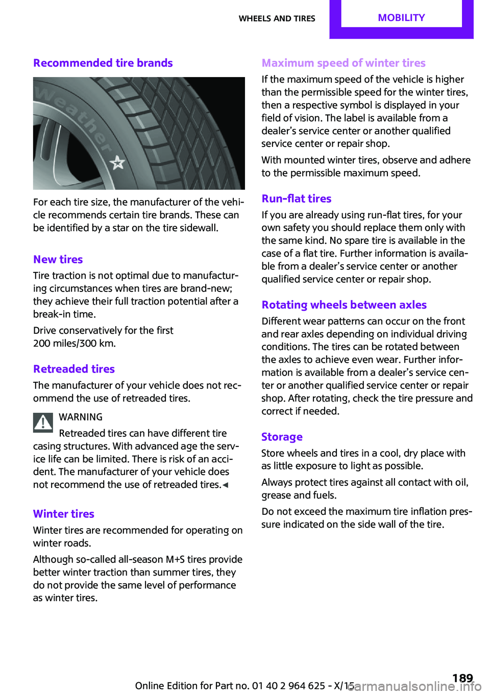
Recommended tire brands
For each tire size, the manufacturer of the vehi‐
cle recommends certain tire brands. These can
be identified by a star on the tire sidewall.
New tires
Tire traction is not optimal due to manufactur‐
ing circumstances when tires are brand-new;
they achieve their full traction potential after a
break-in time.
Drive conservatively for the first
200 miles/300 km.
Retreaded tires The manufacturer of your vehicle does not rec‐
ommend the use of retreaded tires.
WARNING
Retreaded tires can have different tire
casing structures. With advanced age the serv‐
ice life can be limited. There is risk of an acci‐
dent. The manufacturer of your vehicle does
not recommend the use of retreaded tires. ◀
Winter tires
Winter tires are recommended for operating on
winter roads.
Although so-called all-season M+S tires provide
better winter traction than summer tires, they
do not provide the same level of performance
as winter tires.
Maximum speed of winter tires
If the maximum speed of the vehicle is higher
than the permissible speed for the winter tires,
then a respective symbol is displayed in your
field of vision. The label is available from a
dealer’s service center or another qualified
service center or repair shop.
With mounted winter tires, observe and adhere
to the permissible maximum speed.
Run-flat tires If you are already using run-flat tires, for your
own safety you should replace them only with
the same kind. No spare tire is available in the
case of a flat tire. Further information is availa‐
ble from a dealer’s service center or another
qualified service center or repair shop.
Rotating wheels between axles
Different wear patterns can occur on the front
and rear axles depending on individual driving
conditions. The tires can be rotated between
the axles to achieve even wear. Further infor‐
mation is available from a dealer’s service cen‐
ter or another qualified service center or repair
shop. After rotating, check the tire pressure and
correct if needed.
Storage Store wheels and tires in a cool, dry place with
as little exposure to light as possible.
Always protect tires against all contact with oil,
grease and fuels.
Do not exceed the maximum tire inflation pres‐
sure indicated on the side wall of the tire.Seite 189Wheels and tiresMOBILITY189
Online Edition for Part no. 01 40 2 964 625 - X/15
Page 195 of 248
WARNING
The engine compartment accommodates
moving components. Certain components in
the engine compartment can also move with
the vehicle switched off, for example the cooler
fan. There is risk of injuries. Do not reach into
the area of moving parts. Keep articles of cloth‐
ing and hair away from moving parts. ◀
WARNING
There are protruding parts, for example
lock hook, on the inside of the hood. There is
risk of injuries. If the hood is open, pay atten‐
tion to protruding parts and keep these areas
clear. ◀
WARNING
An incorrectly locked hood can open
while driving and restrict visibility. There is risk
of an accident. Stop immediately and correctly
close the hood. ◀
WARNING
Body parts can be jammed on opening
and closing the hood. There is risk of injuries.
Make sure that the area of movement of the
hood is clear during opening and closing. ◀
CAUTION
Folded-away wipers can be jammed
when the hood is opened. There is risk of prop‐
erty damage. Make sure that the wipers with
the wiper blades mounted are folded down
onto the windshield before opening the
hood. ◀
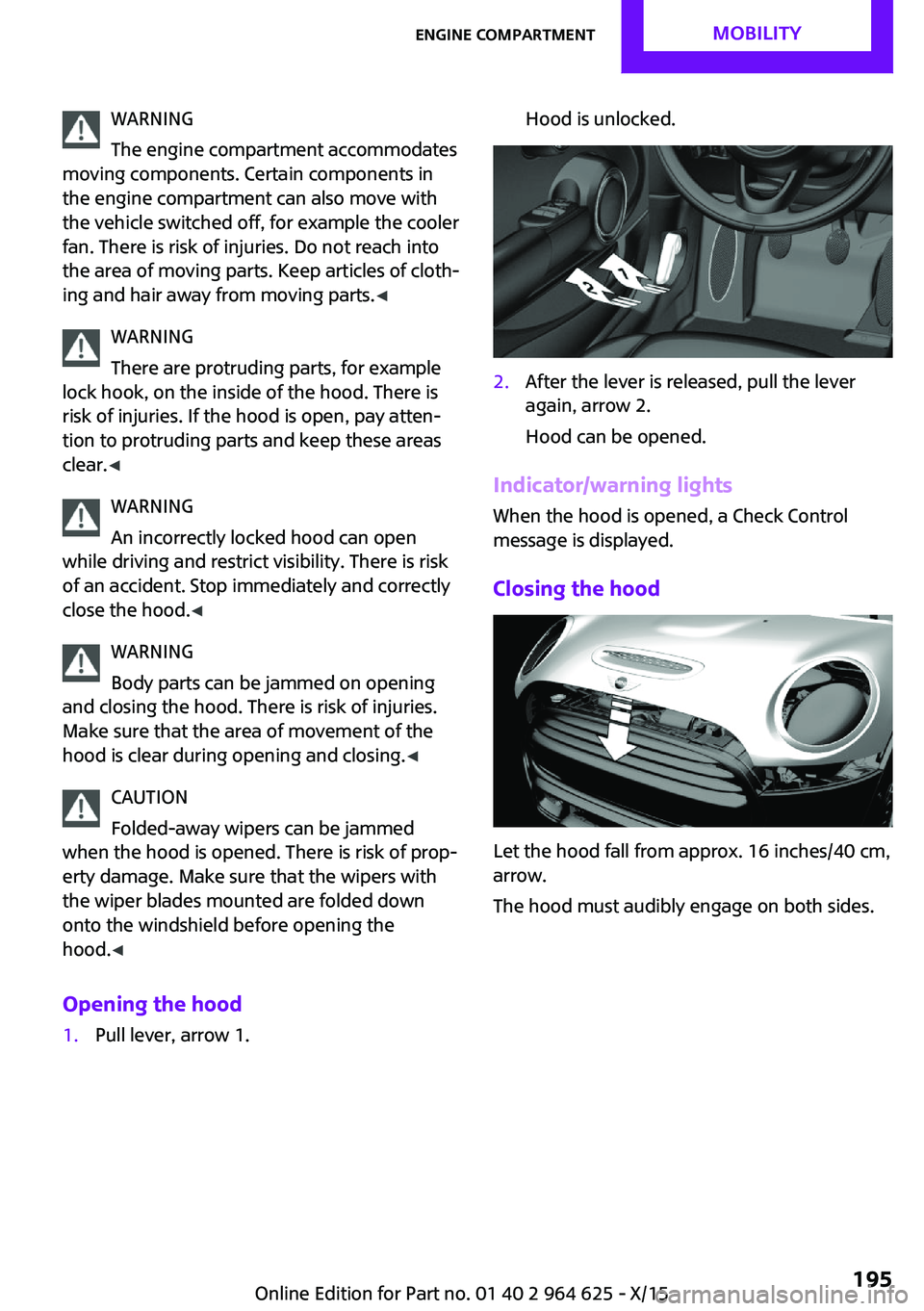
Opening the hood1.Pull lever, arrow 1.Hood is unlocked.2.After the lever is released, pull the lever
again, arrow 2.
Hood can be opened.
Indicator/warning lights
When the hood is opened, a Check Control
message is displayed.
Closing the hood
Let the hood fall from approx. 16 inches/40 cm,
arrow.
The hood must audibly engage on both sides.
Seite 195Engine compartmentMOBILITY195
Online Edition for Part no. 01 40 2 964 625 - X/15
Page 200 of 248

CoolantVehicle features and op‐
tions
This chapter describes all standard, country-
specific and optional features offered with the
series. It also describes features that are not
necessarily available in your car, e. g., due to
the selected options or country versions. This
also applies to safety-related functions and sys‐
tems. The respectively applicable country provi‐
sions must be observed when using the respec‐
tive features and systems.
Information WARNING
With the engine hot and the cooling sys‐
tem open, coolant can escape and lead to
burns. There is risk of injuries. Only open the cooling system with the engine cooled down. ◀
WARNING
Additives are harmful and incorrect addi‐
tives can damage the engine. There is risk of in‐
juries and risk of property damage. Avoid the
contact of articles of clothing, skin or eyes with
additives. Do not swallow any additives. Use
suitable additives only. ◀
Coolant consists of water and additives.
Not all commercially available additives are
suitable for the vehicle. Information about suit‐
able additives is available from a dealer’s serv‐
ice center or another qualified service center or
repair shop.
Coolant level
Overview Open the hood, refer to page 194.The coolant reservoir is in the engine compart‐
ment, refer to page 194.
Checking
There are yellow Min and Max marks in the
coolant reservoir.1.Let the engine cool.2.Turn the lid of the coolant reservoir slightly
counterclockwise to allow any excess pres‐
sure to dissipate, then open it.3.The coolant level is correct if it lies between
the minimum and maximum marks in the
filler neck.Seite 200MOBILITYCoolant200
Online Edition for Part no. 01 40 2 964 625 - X/15
Page 203 of 248
service center or repair shop. Records of regu‐
lar maintenance and repair work should be re‐
tained.
Socket for OBD Onboard
Diagnosis
Information CAUTION
The socket for Onboard Diagnosis is an
intricate component intended to be used in
conjunction with specialized equipment to
check the vehicle’s primary emissions system.
Improper use of the socket for Onboard Diag‐
nosis, or contact with the socket for Onboard
Diagnosis for other than its intended purpose,
can cause vehicle malfunctions and creates
risks of personal and property damage. Given
the foregoing, the manufacture of your vehicle
strongly recommends that access to the socket
for Onboard Diagnosis be limited to a dealer's
service center or another qualified service cen‐
ter or repair shop or other persons that have
the specialized training and equipment for pur‐
poses of properly utilizing the socket for On‐
board Diagnosis. ◀
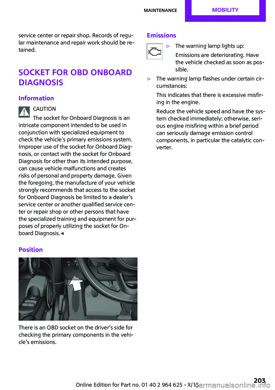
Position
There is an OBD socket on the driver's side for
checking the primary components in the vehi‐
cle's emissions.
Emissions▷The warning lamp lights up:
Emissions are deteriorating. Have
the vehicle checked as soon as pos‐
sible.▷The warning lamp flashes under certain cir‐
cumstances:
This indicates that there is excessive misfir‐
ing in the engine.
Reduce the vehicle speed and have the sys‐
tem checked immediately; otherwise, seri‐
ous engine misfiring within a brief period
can seriously damage emission control
components, in particular the catalytic con‐
verter.Seite 203MaintenanceMOBILITY203
Online Edition for Part no. 01 40 2 964 625 - X/15