MINI COUPE ROADSTER CONVERTIBLE 2012 User Guide
Manufacturer: MINI, Model Year: 2012, Model line: COUPE ROADSTER CONVERTIBLE, Model: MINI COUPE ROADSTER CONVERTIBLE 2012Pages: 283, PDF Size: 9.38 MB
Page 11 of 283
AT A GLANCECockpit
10
Cockpit
Vehicle equipment
In this chapter, all production, country, and
optional equipment that is offered in the model range is described. Equi
pment is also described
that is not available because of, for example,
selected options or coun try version. This also
applies to safety relate d functions and systems.
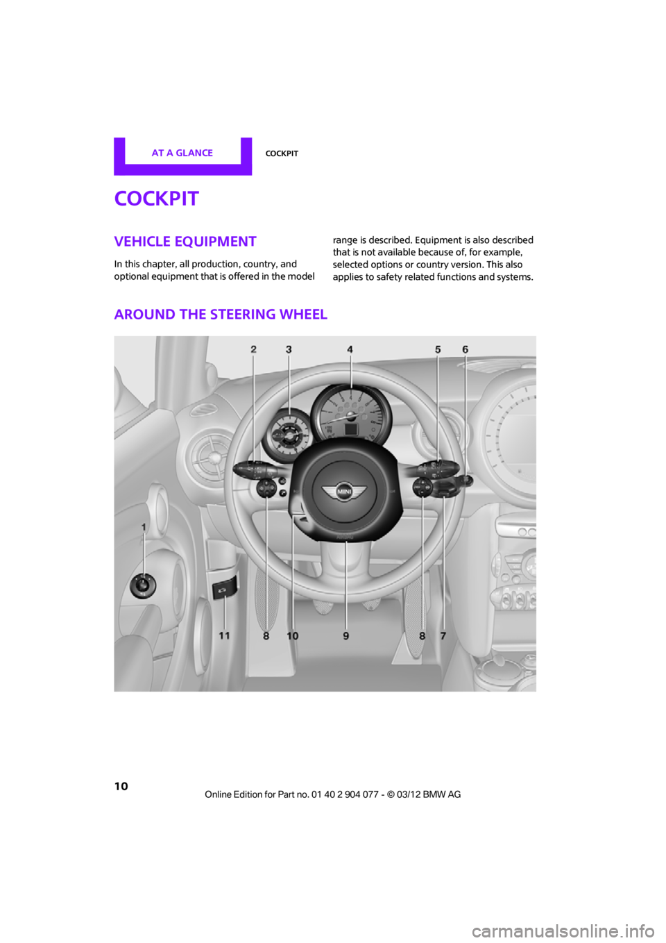
Around the steering wheel
00320051004F004C00510048000300280047004C0057004C005200510003
Page 12 of 283
CockpitAT A GLANCE
11
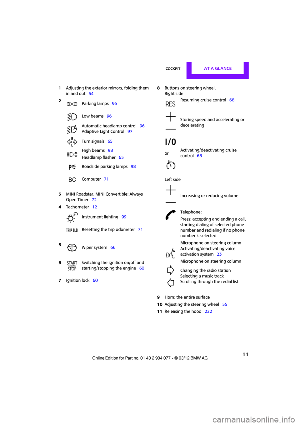
1Adjusting the exterior mirrors, folding them
in and out 54
3 MINI Roadster, MINI Convertible: Always
Open Timer 72
7 Ignition lock 60 8
Buttons on steering wheel,
Right side
Left side
9 Horn: the entire surface
10 Adjusting the steering wheel 55
11 Releasing the hood 222
2
Parking lamps 96
Low beams 96
Automatic headlamp control 96
Adaptive Light Control 97
Turn signals 65
High beams 98
Headlamp flasher 65
Roadside parking lamps 98
Computer 71
4 Tachometer 12
Instrument lighting 99
Resetting the trip odometer 71
5 Wiper system 66
6 Switching the ignition on/off and
starting/stopping the engine
60
Resuming cruise control68
Storing speed and accelerating or
decelerating
or Activating/deactivating cruise
control
68
Increasing or reducing volume
Telephone:
Press: accepting and ending a call,
starting dialing of selected phone
number and redialing if no phone
number is selected
Microphone on steering column
Activating/deactivating voice
activation system 23
Microphone on steering column
Changing the radio station
Selecting a music track
Scrolling through the redial list
00320051004F004C00510048000300280047004C0057004C005200510003
Page 13 of 283
AT A GLANCECockpit
12
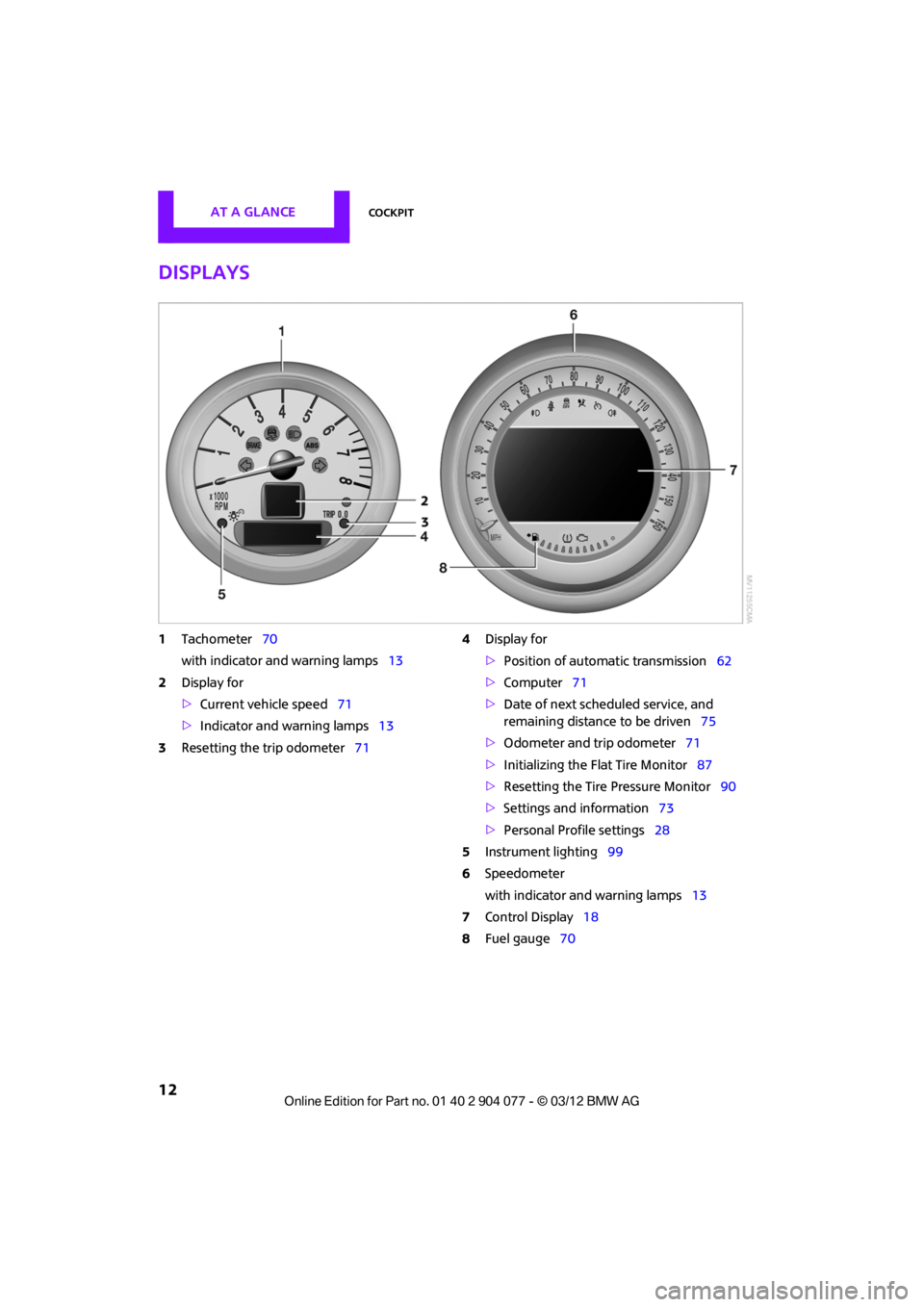
Displays
1Tachometer 70
with indicator and warning lamps 13
2 Display for
>Current vehicle speed 71
> Indicator and warning lamps 13
3 Resetting the trip odometer 714
Display for
>Position of automatic transmission 62
> Computer 71
> Date of next scheduled service, and
remaining distance to be driven 75
> Odometer and trip odometer 71
> Initializing the Flat Tire Monitor 87
> Resetting the Tire Pressure Monitor 90
> Settings and information 73
> Personal Prof ile settings28
5 Instrument lighting 99
6 Speedometer
with indicator and warning lamps 13
7 Control Display 18
8 Fuel gauge 70
00320051004F004C00510048000300280047004C0057004C005200510003
Page 14 of 283
CockpitAT A GLANCE
13
Indicator and warning
lamps
The concept
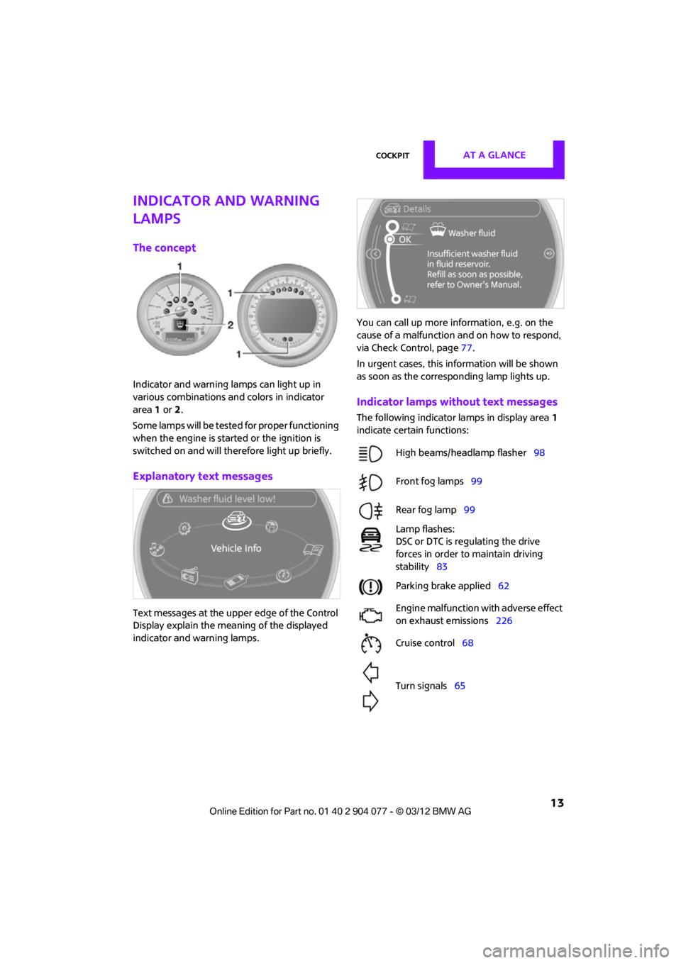
Indicator and warning lamps can light up in
various combinations and colors in indicator
area 1 or 2.
Some lamps will be tested for proper functioning
when the engine is started or the ignition is
switched on and will therefore light up briefly.
Explanatory text messages
Text messages at the uppe r edge of the Control
Display explain the mean ing of the displayed
indicator and warning lamps. You can call up more information, e.g. on the
cause of a malfunction and on how to respond,
via Check Control, page
77.
In urgent cases, this information will be shown
as soon as the corresponding lamp lights up.
Indicator lamps without text messages
The following indicator lamps in display area 1
indicate certain functions:
High beams/headlamp flasher 98
Front fog lamps 99
Rear fog lamp 99
Lamp flashes:
DSC or DTC is regulating the drive
forces in order to maintain driving
stability 83
Parking brake applied 62
Engine malfunction with adverse effect
on exhaust emissions 226
Cruise control 68
Turn signals 65
00320051004F004C00510048000300280047004C0057004C005200510003
Page 15 of 283
AT A GLANCECockpit
14
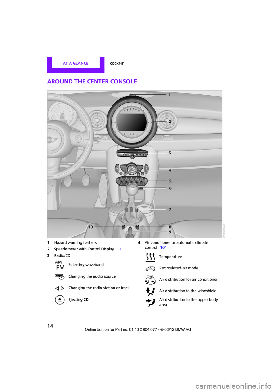
Around the center console
1Hazard warning flashers
2 Speedometer with Control Display 12
3 Radio/CD 4
Air conditioner or automatic climate
control 101
Selecting waveband
Changing the audio source
Changing the radio station or track
Ejecting CD
Temperature
Recirculated-air mode
Air distribution for air conditioner
Air distribution to the windshield
Air distribution to the upper body
area
00320051004F004C00510048000300280047004C0057004C005200510003
Page 16 of 283

CockpitAT A GLANCE
15
5Switches in the center console 6
USB audio interface 160
7 Buttons on the center console
8 Changing to a differen t menu on the Control
Display
9 MINI joystick 17
Move in four directions, turn or press
10 Accessing the main me nu on the Control
Display 18
Air distribution to the footwell
Automatic air distribution and flow
rate
Maximum cooling
or Cooling function
Defrosting windows
Rear window defroster
Windshield heating
Air flow rate
Seat heating
53
Power windows 38
MINI Convertible: central power
window unit 39
Rear fog lamp 98
Front fog lamps 98
Central locking system, inside 32
Sport button85
Driving stability control systems
Dynamic Stability Control DSC 83
Dynamic Traction Control DTC 84
00320051004F004C00510048000300280047004C0057004C005200510003
Page 17 of 283
AT A GLANCECockpit
16
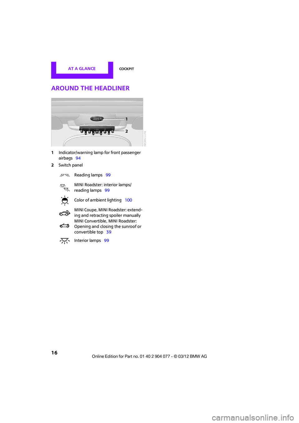
Around the headliner
1Indicator/warning lamp for front passenger
airbags 94
2 Switch panel
Reading lamps 99
MINI Roadster: interior lamps/
reading lamps 99
Color of ambient lighting 100
MINI Coupe, MINI Roadster: extend-
ing and retracting spoiler manually
MINI Convertible, MINI Roadster:
Opening and closing the sunroof or
convertible top 39
Interior lamps 99
00320051004F004C00510048000300280047004C0057004C005200510003
Page 18 of 283
Onboard computerAT A GLANCE
17
Onboard computer
Vehicle equipment
In this chapter, all production, country, and
optional equipment that is offered in the model
range is described. Equipment is also described
that is not available because of, for example,
selected options or count ry version. This also
applies to safety related functions and systems.
The concept
The onboard computer integrates the functions
of a large number of switches. This allows these
functions to be operated from a single central
position. The following section provides an
introduction to basic menu navigation. The con-
trol of the individual functions is described in
connection with the relevant equipment.
Make entries only when traffic and road
conditions permit; otherwise, you may
endanger vehicle occu pants and other road
users by being distracted.<
Overview of operating
elements
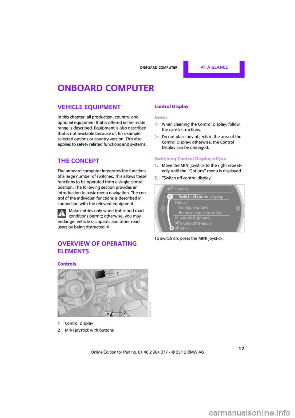
Controls
1 Control Display
2 MINI joystick with buttons
Control Display
Notes
>When cleaning the Control Display, follow
the care instructions.
> Do not place any objects in the area of the
Control Display; otherwise, the Control
Display can be damaged.
Switching Control Display off/on
1.Move the MINI joystick to the right repeat-
edly until the "Options" menu is displayed.
2. "Switch off control display"
To switch on, press the MINI joystick.
00320051004F004C00510048000300280047004C0057004C005200510003
Page 19 of 283
AT A GLANCEOnboard computer
18
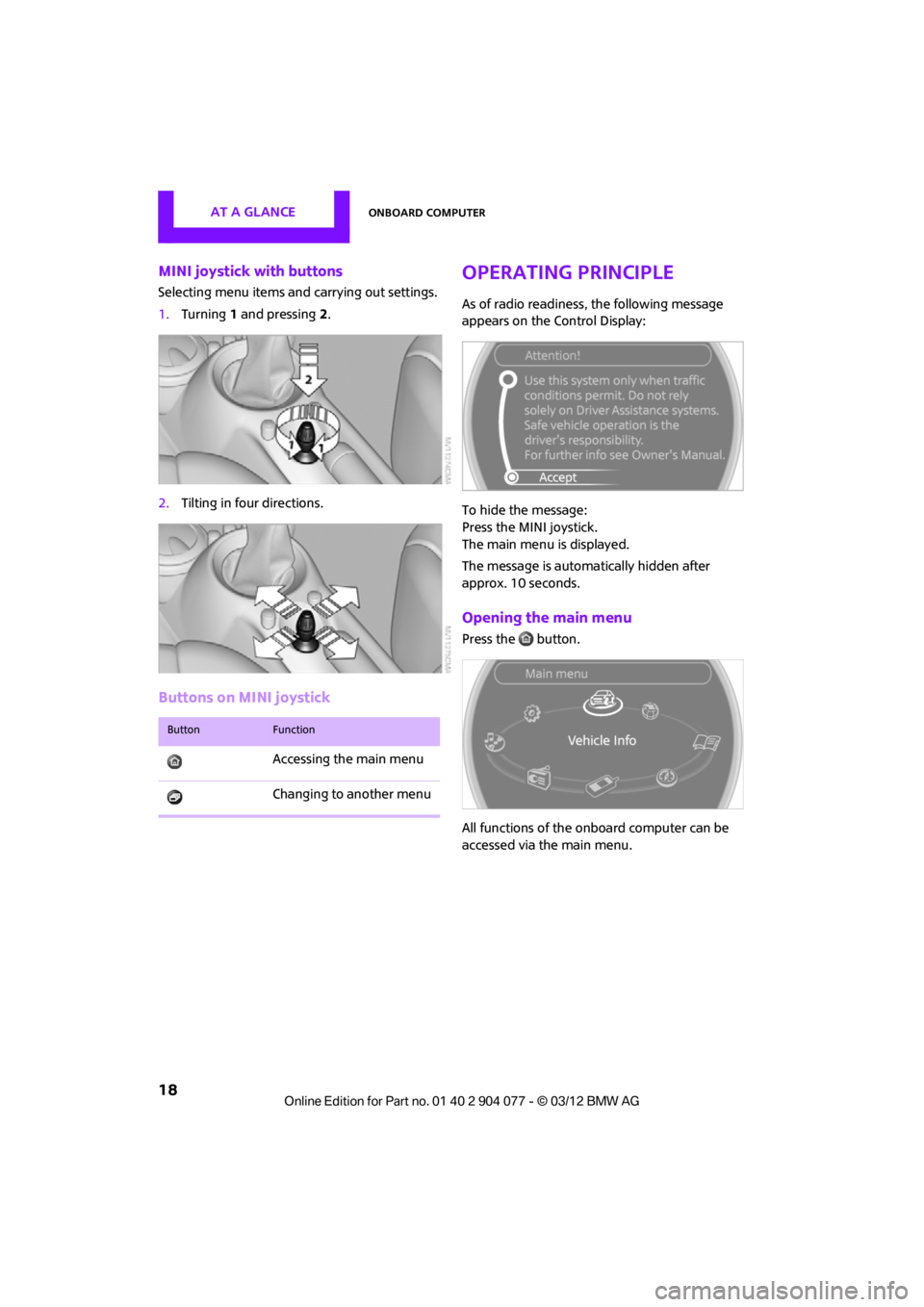
MINI joystick with buttons
Selecting menu items and carrying out settings.
1. Turning 1 and pressing 2.
2. Tilting in four directions.
Buttons on MINI joystick
Operating principle
As of radio readiness, the following message
appears on the Control Display:
To hide the message:
Press the MINI joystick.
The main menu is displayed.
The message is automa tically hidden after
approx. 10 seconds.
Opening the main menu
Press the button.
All functions of the onboard computer can be
accessed via the main menu.
ButtonFunction
Accessing the main menu
Changing to another menu
00320051004F004C00510048000300280047004C0057004C005200510003
Page 20 of 283
Onboard computerAT A GLANCE
19
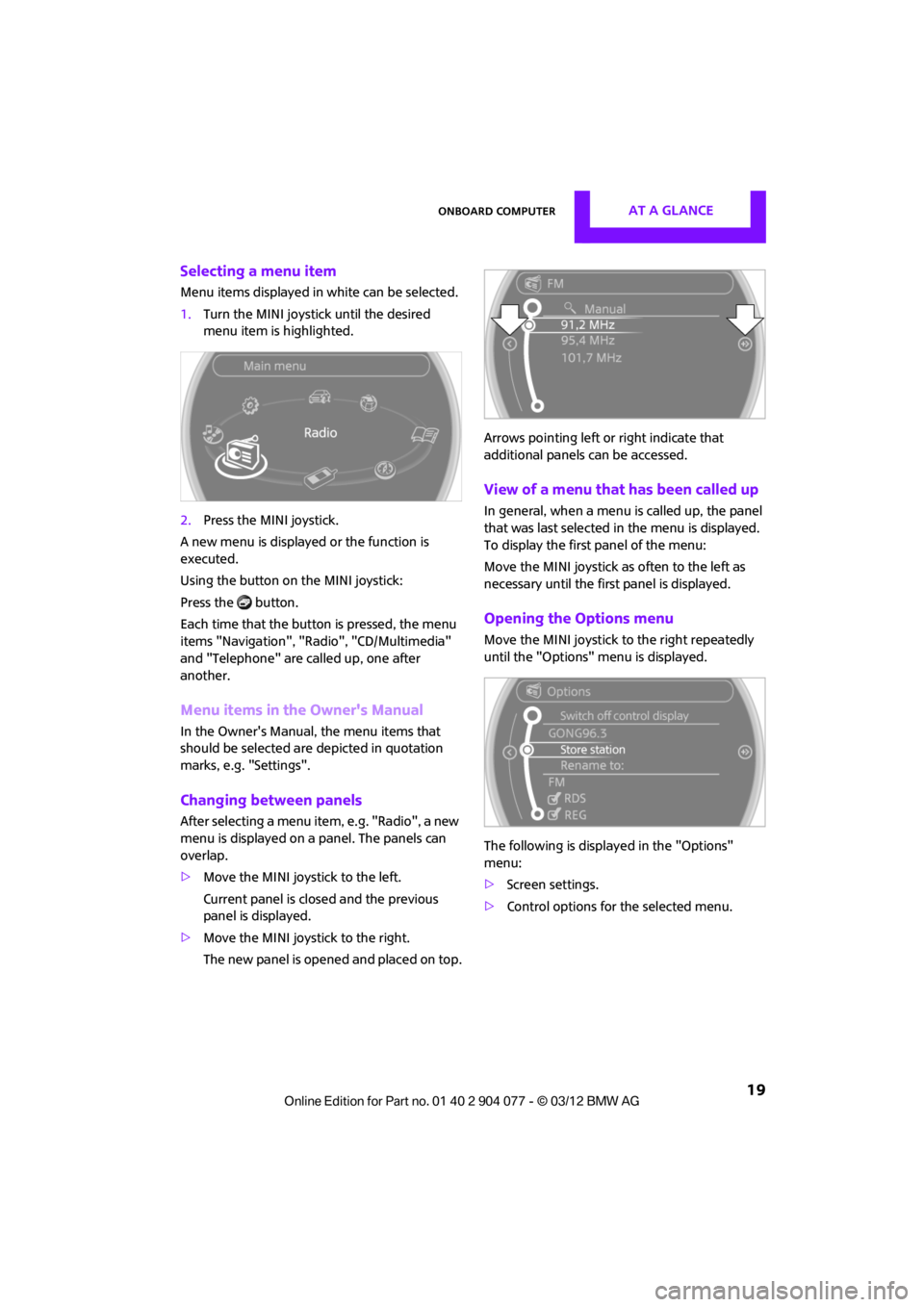
Selecting a menu item
Menu items displayed in white can be selected.
1.Turn the MINI joystick until the desired
menu item is highlighted.
2. Press the MINI joystick.
A new menu is displayed or the function is
executed.
Using the button on the MINI joystick:
Press the button.
Each time that the button is pressed, the menu
items "Navigation", "Rad io", "CD/Multimedia"
and "Telephone" are called up, one after
another.
Menu items in the Owner's Manual
In the Owner's Manual, the menu items that
should be selected are depicted in quotation
marks, e.g. "Settings".
Changing between panels
After selecting a menu item, e.g. "Radio", a new
menu is displayed on a panel. The panels can
overlap.
> Move the MINI joystick to the left.
Current panel is closed and the previous
panel is displayed.
> Move the MINI joystick to the right.
The new panel is opened and placed on top. Arrows pointing left or right indicate that
additional panels can be accessed.
View of a menu that has been called up
In general, when a menu is called up, the panel
that was last selected in
the menu is displayed.
To display the first panel of the menu:
Move the MINI joystick as often to the left as
necessary until the first panel is displayed.
Opening the Options menu
Move the MINI joystick to the right repeatedly
until the "Options" menu is displayed.
The following is displa yed in the "Options"
menu:
> Screen settings.
> Control options for the selected menu.
00320051004F004C00510048000300280047004C0057004C005200510003