bulb MINI COUPE ROADSTER CONVERTIBLE 2015 Owners Manual
[x] Cancel search | Manufacturer: MINI, Model Year: 2015, Model line: COUPE ROADSTER CONVERTIBLE, Model: MINI COUPE ROADSTER CONVERTIBLE 2015Pages: 231, PDF Size: 5.56 MB
Page 61 of 231

Excessive application of the parking brake can
block the rear wheels and lead to fishtailing of
the vehicle. ŌŚĆ
The brake lights do not light up when the parkŌĆÉ
ing brake is pulled.
Turn signal, high-beams,
headlight flasher1Turn signal2Switching on the high-beams3Switching off the high-beams/headlight
flasher
Turn signal
Press the lever beyond the resistance point.
To switch off manually, press the lever to the
resistance point.
Unusually rapid flashing of the indicator lamp
indicates that a turn signal bulb has failed.
Signaling a turn briefly Press the lever to the resistance point and hold
it there for as long as you want the turn signal
to flash.
Triple turn signal activation Press the lever to the resistance point.
The turn signal flashes three times.
This function can be activated or deactivated:1.Switch on the ignition, refer to page 57.2.Press the button on the turn indicator lever
repeatedly until "SET/INFO" is displayed.3.Press and hold the button until the display
changes.4.Press the button repeatedly until the symŌĆÉ
bol and "SET" are displayed.5.Press and hold the button until the display
changes.6.Press the button repeatedly until the symŌĆÉ
bol shown is displayed, arrow.7.Press and hold the button until the display
changes.8.Press the button to select:Seite 59DrivingCONTROLS59
Online Edition for Part no. 01 40 2 961 029 - II/15
Page 180 of 231
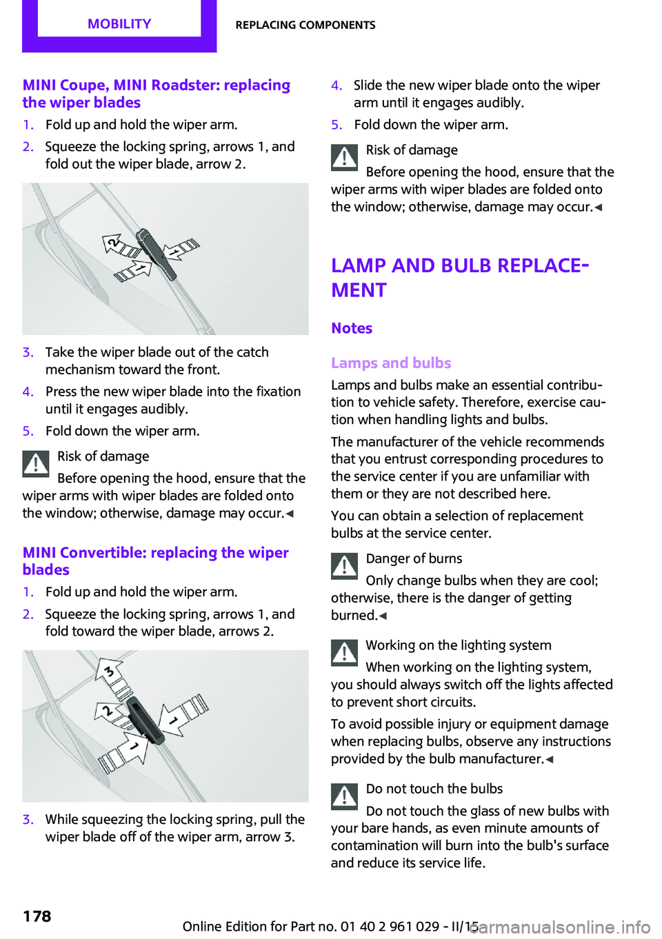
MINI Coupe, MINI Roadster: replacing
the wiper blades1.Fold up and hold the wiper arm.2.Squeeze the locking spring, arrows 1, and
fold out the wiper blade, arrow 2.3.Take the wiper blade out of the catch
mechanism toward the front.4.Press the new wiper blade into the fixation
until it engages audibly.5.Fold down the wiper arm.
Risk of damage
Before opening the hood, ensure that the
wiper arms with wiper blades are folded onto
the window; otherwise, damage may occur. ŌŚĆ
MINI Convertible: replacing the wiper
blades
1.Fold up and hold the wiper arm.2.Squeeze the locking spring, arrows 1, and
fold toward the wiper blade, arrows 2.3.While squeezing the locking spring, pull the
wiper blade off of the wiper arm, arrow 3.4.Slide the new wiper blade onto the wiper
arm until it engages audibly.5.Fold down the wiper arm.
Risk of damage
Before opening the hood, ensure that the
wiper arms with wiper blades are folded onto
the window; otherwise, damage may occur. ŌŚĆ
Lamp and bulb replaceŌĆÉ
ment
Notes
Lamps and bulbs Lamps and bulbs make an essential contribuŌĆÉ
tion to vehicle safety. Therefore, exercise cauŌĆÉ
tion when handling lights and bulbs.
The manufacturer of the vehicle recommends
that you entrust corresponding procedures to
the service center if you are unfamiliar with
them or they are not described here.
You can obtain a selection of replacement
bulbs at the service center.
Danger of burns
Only change bulbs when they are cool;
otherwise, there is the danger of getting
burned. ŌŚĆ
Working on the lighting system
When working on the lighting system,
you should always switch off the lights affected
to prevent short circuits.
To avoid possible injury or equipment damage
when replacing bulbs, observe any instructions
provided by the bulb manufacturer. ŌŚĆ
Do not touch the bulbs
Do not touch the glass of new bulbs with
your bare hands, as even minute amounts of
contamination will burn into the bulb's surface
and reduce its service life.
Seite 178MOBILITYReplacing components178
Online Edition for Part no. 01 40 2 961 029 - II/15
Page 181 of 231
Use a clean tissue, cloth or something similar,
or hold the bulb by its base. ŌŚĆ
Caring for the headlights, refer to page 195.
For bulb replacement that is not described
here, please contact the service center or a
workshop that works according to the repair
procedures of the manufacturer with correŌĆÉ
spondingly trained personnel.
For checking and adjusting headlight aim,
please contact your MINI dealer.
Light-emitting diodes LEDs In some equipment, the light source is provided
by light-emitting diodes behind a cover.
These light-emitting diodes, which operate usŌĆÉ
ing a concept similar to that applied in convenŌĆÉ
tional lasers, are designated as Class 1 light-
emitting diodes.
Do not remove the covers
Do not remove the covers, and never
stare into the unfiltered light for several hours;
otherwise, irritation of the retina could result. ŌŚĆ
Headlight glass Condensation can form on the inside of the
headlights in cool or humid weather. When the
light is switched on, the condensation evapoŌĆÉ
rates after a short time. The headlights do not
need to be changed.
If the condensation in the headlights does not
evaporate after trips with the lights switched
on, and the amount of moisture in the headŌĆÉ
lights increases, for example if water droplets
form, have them checked by your service cenŌĆÉ
ter.
Bi-xenon headlights
These bulbs have a very long life and the likeliŌĆÉ
hood of failure is very low, provided that they
are not switched on and off excessively. If a
bulb should nevertheless fail, you can continue
driving cautiously with the front fog lights, proŌĆÉ
vided this is permitted by local laws.Do not perform work/bulb replacement
on xenon headlamps
Have any work on the xenon lighting system,
including bulb replacement, performed only by
a service center.
Due to the high voltage present in the system,
there is the danger of fatal injuries if work is
carried out improperly. ŌŚĆ
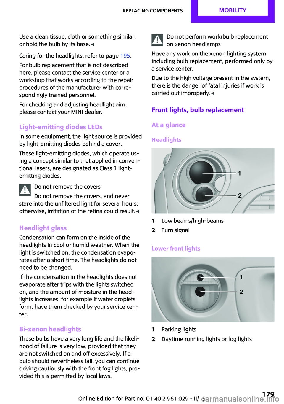
Front lights, bulb replacement
At a glance
Headlights1Low beams/high-beams2Turn signal
Lower front lights
1Parking lights2Daytime running lights or fog lightsSeite 179Replacing componentsMOBILITY179
Online Edition for Part no. 01 40 2 961 029 - II/15
Page 182 of 231
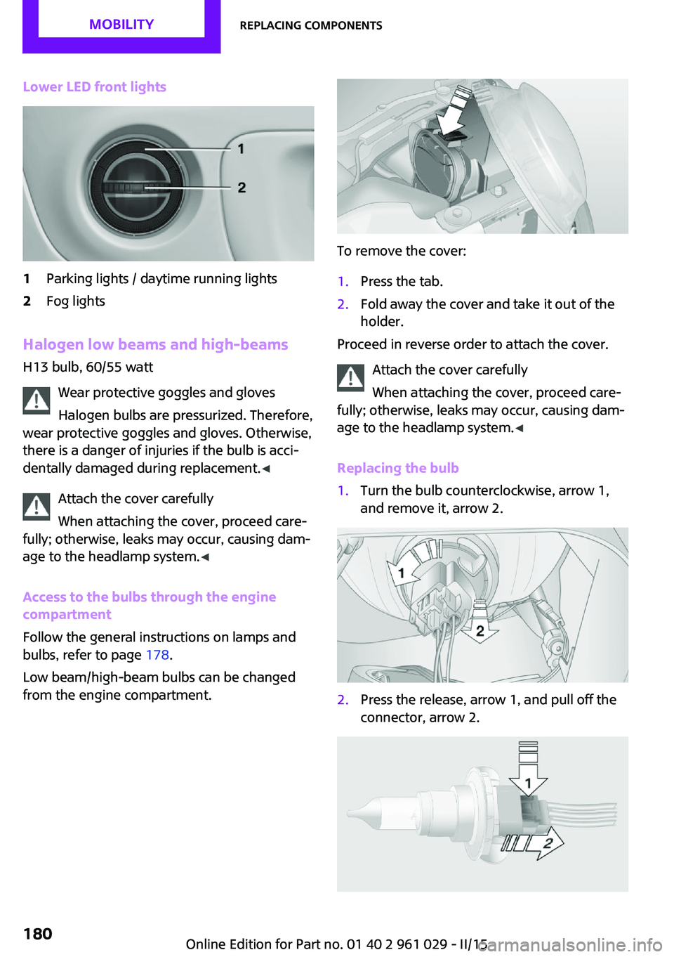
Lower LED front lights1Parking lights / daytime running lights2Fog lights
Halogen low beams and high-beams
H13 bulb, 60/55 watt
Wear protective goggles and glovesHalogen bulbs are pressurized. Therefore,
wear protective goggles and gloves. Otherwise,
there is a danger of injuries if the bulb is acciŌĆÉ
dentally damaged during replacement. ŌŚĆ
Attach the cover carefully
When attaching the cover, proceed careŌĆÉ
fully; otherwise, leaks may occur, causing damŌĆÉ
age to the headlamp system. ŌŚĆ
Access to the bulbs through the engine
compartment
Follow the general instructions on lamps and
bulbs, refer to page 178.
Low beam/high-beam bulbs can be changed
from the engine compartment.
To remove the cover:
1.Press the tab.2.Fold away the cover and take it out of the
holder.
Proceed in reverse order to attach the cover.
Attach the cover carefully
When attaching the cover, proceed careŌĆÉ
fully; otherwise, leaks may occur, causing damŌĆÉ
age to the headlamp system. ŌŚĆ
Replacing the bulb
1.Turn the bulb counterclockwise, arrow 1,
and remove it, arrow 2.2.Press the release, arrow 1, and pull off the
connector, arrow 2.Seite 180MOBILITYReplacing components180
Online Edition for Part no. 01 40 2 961 029 - II/15
Page 183 of 231
3.Insert the new bulb and attach the cover in
reverse order.
LED parking lights/LED fog lights/LED
daytime running lights
Follow the general instructions on lamps and
bulbs, refer to page 178.
Lights are implemented using LED technology.
Contact your service center in the event of a
malfunction.
Turn signals/parking lights/roadside
parking lights/fog lights/and daytime
running lights
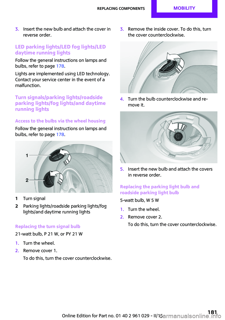
Access to the bulbs via the wheel housing
Follow the general instructions on lamps and
bulbs, refer to page 178.
1Turn signal2Parking lights/roadside parking lights/fog
lights/and daytime running lights
Replacing the turn signal bulb
21-watt bulb, P 21 W, or PY 21 W
1.Turn the wheel.2.Remove cover 1.
To do this, turn the cover counterclockwise.3.Remove the inside cover. To do this, turn
the cover counterclockwise.4.Turn the bulb counterclockwise and reŌĆÉ
move it.5.Insert the new bulb and attach the covers
in reverse order.
Replacing the parking light bulb and
roadside parking light bulb
5-watt bulb, W 5 W
1.Turn the wheel.2.Remove cover 2.
To do this, turn the cover counterclockwise.Seite 181Replacing componentsMOBILITY181
Online Edition for Part no. 01 40 2 961 029 - II/15
Page 184 of 231
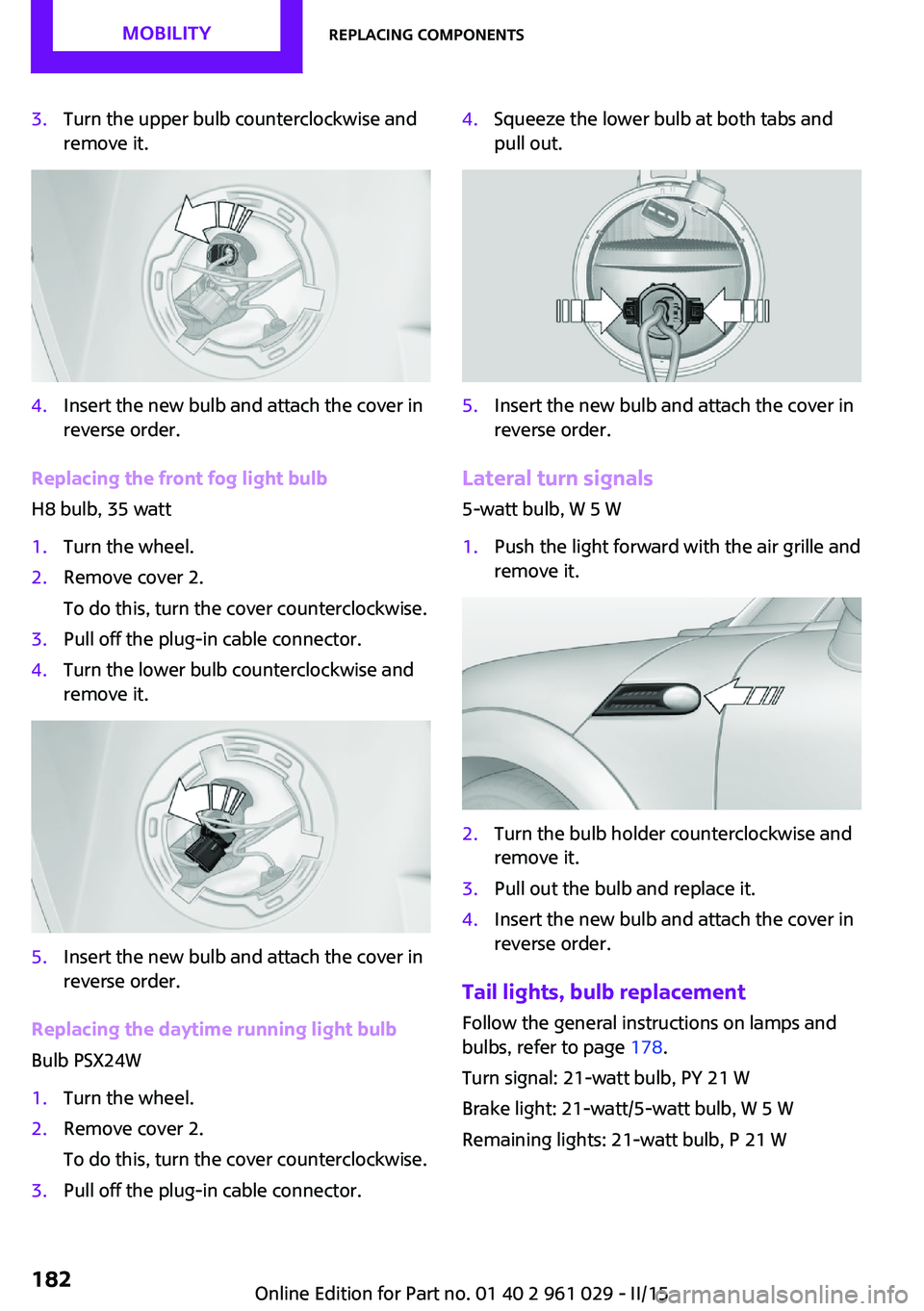
3.Turn the upper bulb counterclockwise and
remove it.4.Insert the new bulb and attach the cover in
reverse order.
Replacing the front fog light bulb
H8 bulb, 35 watt
1.Turn the wheel.2.Remove cover 2.
To do this, turn the cover counterclockwise.3.Pull off the plug-in cable connector.4.Turn the lower bulb counterclockwise and
remove it.5.Insert the new bulb and attach the cover in
reverse order.
Replacing the daytime running light bulb
Bulb PSX24W
1.Turn the wheel.2.Remove cover 2.
To do this, turn the cover counterclockwise.3.Pull off the plug-in cable connector.4.Squeeze the lower bulb at both tabs and
pull out.5.Insert the new bulb and attach the cover in
reverse order.
Lateral turn signals
5-watt bulb, W 5 W
1.Push the light forward with the air grille and
remove it.2.Turn the bulb holder counterclockwise and
remove it.3.Pull out the bulb and replace it.4.Insert the new bulb and attach the cover in
reverse order.
Tail lights, bulb replacement
Follow the general instructions on lamps and
bulbs, refer to page 178.
Turn signal: 21-watt bulb, PY 21 W
Brake light: 21-watt/5-watt bulb, W 5 W
Remaining lights: 21-watt bulb, P 21 W
Seite 182MOBILITYReplacing components182
Online Edition for Part no. 01 40 2 961 029 - II/15
Page 185 of 231
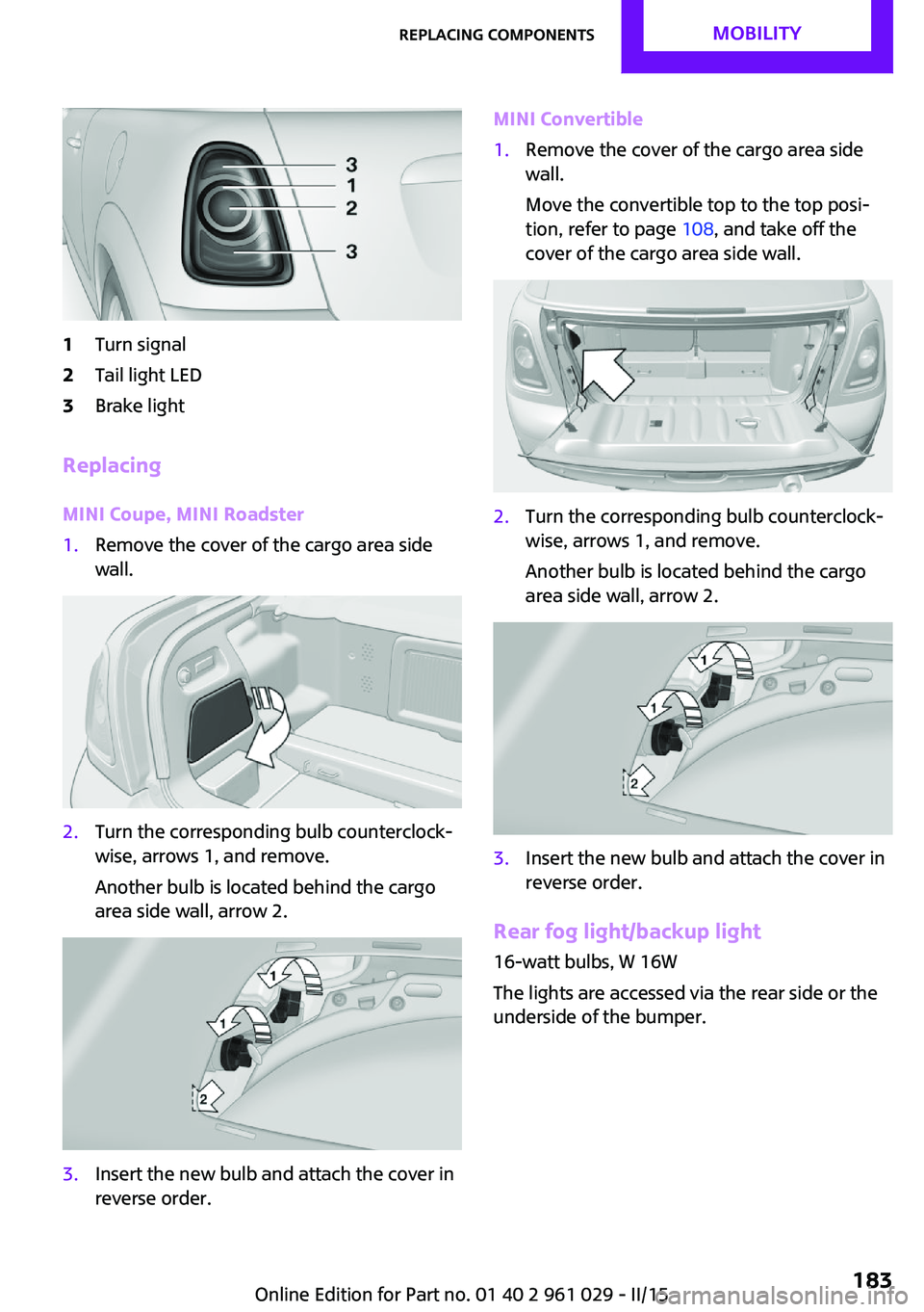
1Turn signal2Tail light LED3Brake light
Replacing
MINI Coupe, MINI Roadster
1.Remove the cover of the cargo area side
wall.2.Turn the corresponding bulb counterclockŌĆÉ
wise, arrows 1, and remove.
Another bulb is located behind the cargo
area side wall, arrow 2.3.Insert the new bulb and attach the cover in
reverse order.MINI Convertible1.Remove the cover of the cargo area side
wall.
Move the convertible top to the top posiŌĆÉ
tion, refer to page 108, and take off the
cover of the cargo area side wall.2.Turn the corresponding bulb counterclockŌĆÉ
wise, arrows 1, and remove.
Another bulb is located behind the cargo
area side wall, arrow 2.3.Insert the new bulb and attach the cover in
reverse order.
Rear fog light/backup light
16-watt bulbs, W 16W
The lights are accessed via the rear side or the
underside of the bumper.
Seite 183Replacing componentsMOBILITY183
Online Edition for Part no. 01 40 2 961 029 - II/15
Page 186 of 231
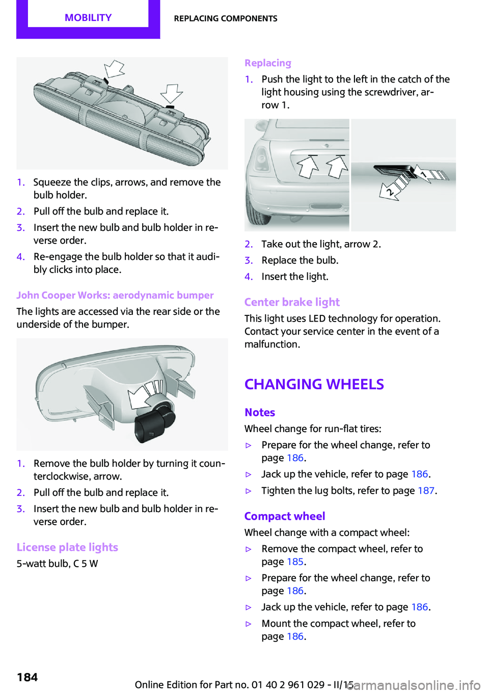
1.Squeeze the clips, arrows, and remove the
bulb holder.2.Pull off the bulb and replace it.3.Insert the new bulb and bulb holder in reŌĆÉ
verse order.4.Re-engage the bulb holder so that it audiŌĆÉ
bly clicks into place.
John Cooper Works: aerodynamic bumper
The lights are accessed via the rear side or the
underside of the bumper.
1.Remove the bulb holder by turning it counŌĆÉ
terclockwise, arrow.2.Pull off the bulb and replace it.3.Insert the new bulb and bulb holder in reŌĆÉ
verse order.
License plate lights
5-watt bulb, C 5 W
Replacing1.Push the light to the left in the catch of the
light housing using the screwdriver, arŌĆÉ
row 1.2.Take out the light, arrow 2.3.Replace the bulb.4.Insert the light.
Center brake light
This light uses LED technology for operation.
Contact your service center in the event of a
malfunction.
Changing wheels NotesWheel change for run-flat tires:
Ō¢ĘPrepare for the wheel change, refer to
page 186.Ō¢ĘJack up the vehicle, refer to page 186.Ō¢ĘTighten the lug bolts, refer to page 187.
Compact wheel
Wheel change with a compact wheel:
Ō¢ĘRemove the compact wheel, refer to
page 185.Ō¢ĘPrepare for the wheel change, refer to
page 186.Ō¢ĘJack up the vehicle, refer to page 186.Ō¢ĘMount the compact wheel, refer to
page 186.Seite 184MOBILITYReplacing components184
Online Edition for Part no. 01 40 2 961 029 - II/15
Page 211 of 231
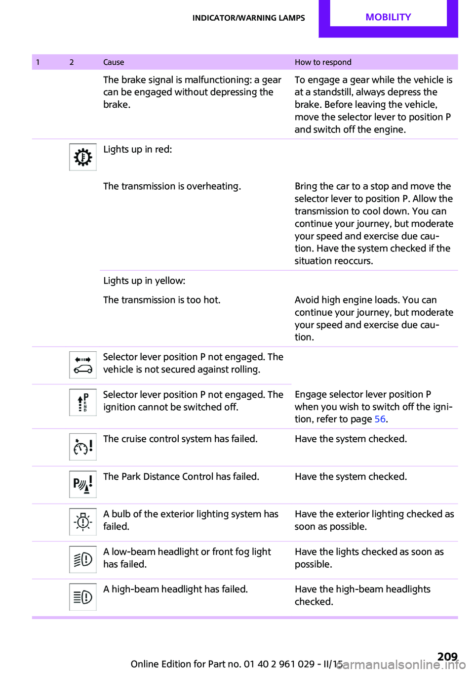
12CauseHow to respondThe brake signal is malfunctioning: a gear
can be engaged without depressing the
brake.To engage a gear while the vehicle is
at a standstill, always depress the
brake. Before leaving the vehicle,
move the selector lever to position P
and switch off the engine.Lights up in red:The transmission is overheating.Bring the car to a stop and move the
selector lever to position P. Allow the
transmission to cool down. You can
continue your journey, but moderate
your speed and exercise due cauŌĆÉ
tion. Have the system checked if the
situation reoccurs.Lights up in yellow:The transmission is too hot.Avoid high engine loads. You can
continue your journey, but moderate
your speed and exercise due cauŌĆÉ
tion.Selector lever position P not engaged. The
vehicle is not secured against rolling.Selector lever position P not engaged. The
ignition cannot be switched off.Engage selector lever position P
when you wish to switch off the igniŌĆÉ
tion, refer to page 56.The cruise control system has failed.Have the system checked.The Park Distance Control has failed.Have the system checked.A bulb of the exterior lighting system has
failed.Have the exterior lighting checked as
soon as possible.A low-beam headlight or front fog light
has failed.Have the lights checked as soon as
possible.A high-beam headlight has failed.Have the high-beam headlights
checked.Seite 209Indicator/warning lampsMOBILITY209
Online Edition for Part no. 01 40 2 961 029 - II/15
Page 220 of 231

Everything from A to ZIndexA
ABS, Antilock Brake SysŌĆÉ tem 91
Acoustic signal, refer to Check Control 73
Activated charcoal filter with automatic climate conŌĆÉ
trol 103
Adaptive Light Control 77
Additives, engine oil 173
Airbags 81
Airbags, indicator/warning light 83
Air circulation, refer to RecirŌĆÉ culated air mode, air condiŌĆÉ
tioner 100
Air circulation, refer to RecirŌĆÉ culated air mode, automatic
climate control 102
Air conditioning 99
Air conditioning mode, air conditioner 99
Air conditioning mode, autoŌĆÉ matic climate control 101
Air distribution, air condiŌĆÉ tioner, manual 100
Air distribution, autoŌĆÉ matic 102
Air distribution, automatic cliŌĆÉ mate control, manual 103
Air distribution, individual 100
Air drying, refer to Cooling function 103
Air flow rate for air condiŌĆÉ tioner 100
Air flow rate with automatic climate control 102
Air pressure, refer to Tire inflaŌĆÉ tion pressure 156
Air supply, air conditioner 99 Air supply, automatic climate
control 101
Alarm system 31
Alarm system, avoiding uninŌĆÉ tentional alarms 32
Alarm system, ending an alarm 31
Alarm system, interior motion sensor 32
Alarm system, tilt alarm senŌĆÉ sor 32
Always Open Timer 68
Ambient lighting 79
Antifreeze, washer fluid 62
Antilock Brake System, ABS 91
Anti-slip control, refer to DyŌĆÉ namic Stability Control
DSC 91
Anti-theft protection 21
Approved engine oils 173
Ashtray 105
Assistance, roadside 189
Assistance when driving off, refer to Hill drive-off assisŌĆÉ
tant 93
Assistance with starting enŌĆÉ gine, refer to Jump-startŌĆÉ
ing 189
Automatic air distribution 102
Automatic air flow 102
Automatic car wash 194
Automatic climate conŌĆÉ trol 101
Automatic climate control, auŌĆÉ tomatic air distribution 102
Automatic, cruise control 96
Automatic headlight conŌĆÉ trol 75
Automatic rear spoiler 93 Automatic transmission with
Steptronic 63
AUTO program with autoŌĆÉ matic climate control 102
AUX-IN port 134
Average fuel consumption 68
Average fuel consumption, setting the units 70
Average speed 68
Average speed, refer to ComŌĆÉ puter 67
B Backrest curvature, refer to Lumbar support 46
Backrests, refer to Seats 45
Backup lights, bulb replaceŌĆÉ ment 182
Battery disposal 31
Battery, refer to Vehicle batŌĆÉ tery 187
Battery, remote control 20
Battery replacement, remote control 31
Belts, refer to Safety belts 47
Belt tensioners, refer to Safety belts 47
Bi-xenon headlights 179
Brake assistant 91
Brake discs, breaking in 114
Brake fluid, refer to Service reŌĆÉ quirements 71
Brake force distribution, elecŌĆÉ tronic 91
Brake pads, breaking in 114
Brake, refer to Parking brake 58
Brakes, MINI maintenance system 175 Seite 218REFERENCEEverything from A to Z218
Online Edition for Part no. 01 40 2 961 029 - II/15