display MINI Paceman 2014 Owner's Guide
[x] Cancel search | Manufacturer: MINI, Model Year: 2014, Model line: Paceman, Model: MINI Paceman 2014Pages: 218, PDF Size: 5.5 MB
Page 63 of 218
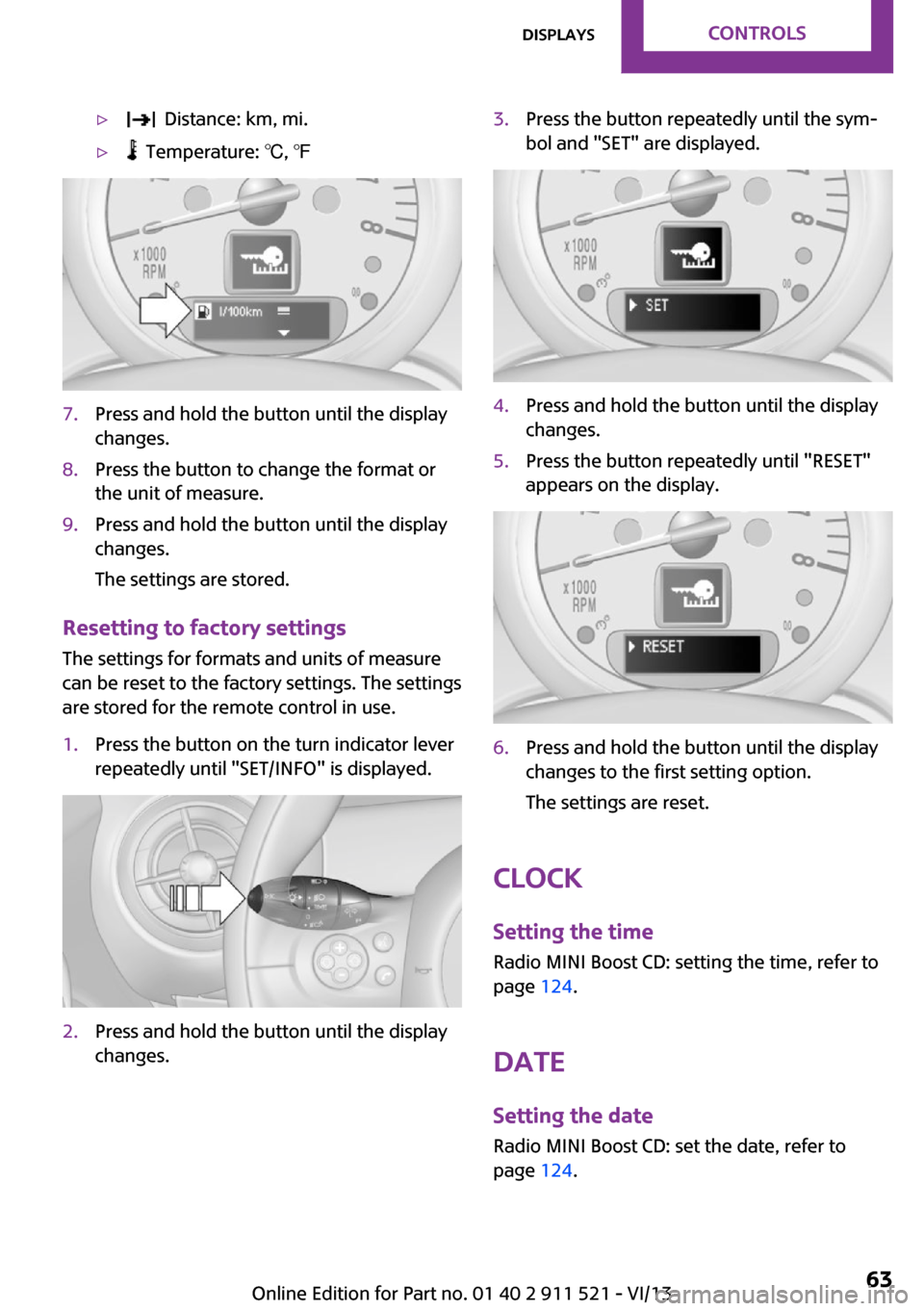
▷ Distance: km, mi.▷ Temperature: ℃, ℉7.Press and hold the button until the display
changes.8.Press the button to change the format or
the unit of measure.9.Press and hold the button until the display
changes.
The settings are stored.
Resetting to factory settings
The settings for formats and units of measure
can be reset to the factory settings. The settings
are stored for the remote control in use.
1.Press the button on the turn indicator lever
repeatedly until "SET/INFO" is displayed.2.Press and hold the button until the display
changes.3.Press the button repeatedly until the sym‐
bol and "SET" are displayed.4.Press and hold the button until the display
changes.5.Press the button repeatedly until "RESET"
appears on the display.6.Press and hold the button until the display
changes to the first setting option.
The settings are reset.
Clock
Setting the time Radio MINI Boost CD: setting the time, refer to
page 124.
Date
Setting the date
Radio MINI Boost CD: set the date, refer to
page 124.
Seite 63DisplaysControls63
Online Edition for Part no. 01 40 2 911 521 - VI/13
Page 64 of 218
Service requirements
The remaining driving distance and the date of
the next scheduled service are displayed briefly
immediately after you start the engine or
switch on the ignition.
The current service requirements can be read
out from the remote control by the service spe‐
cialist.
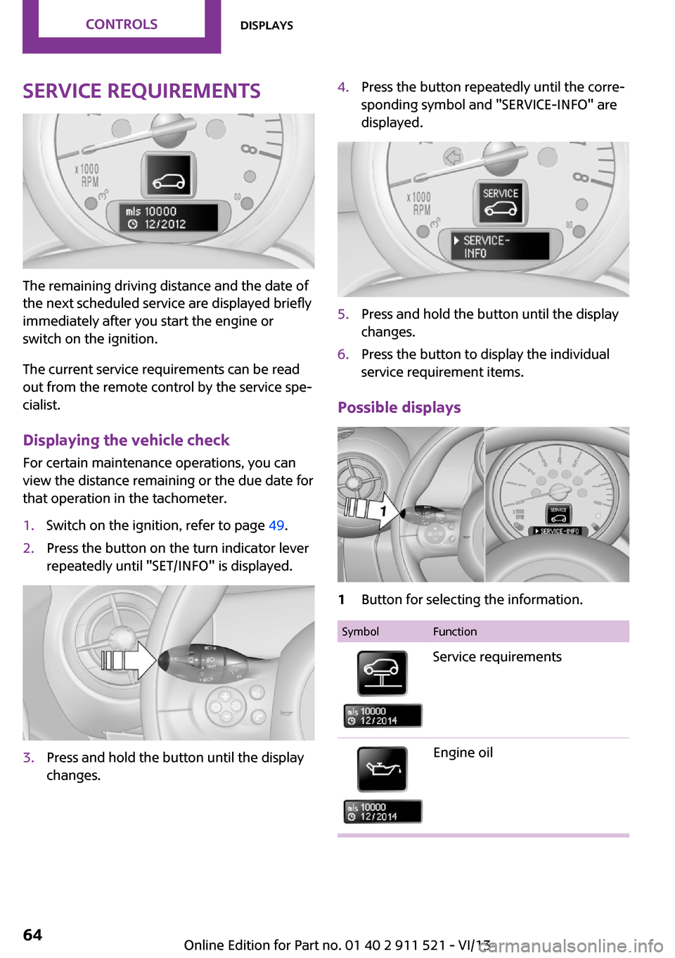
Displaying the vehicle check
For certain maintenance operations, you can
view the distance remaining or the due date for
that operation in the tachometer.
1.Switch on the ignition, refer to page 49.2.Press the button on the turn indicator lever
repeatedly until "SET/INFO" is displayed.3.Press and hold the button until the display
changes.4.Press the button repeatedly until the corre‐
sponding symbol and "SERVICE-INFO" are
displayed.5.Press and hold the button until the display
changes.6.Press the button to display the individual
service requirement items.
Possible displays
1Button for selecting the information.SymbolFunctionService requirementsEngine oilSeite 64ControlsDisplays64
Online Edition for Part no. 01 40 2 911 521 - VI/13
Page 65 of 218
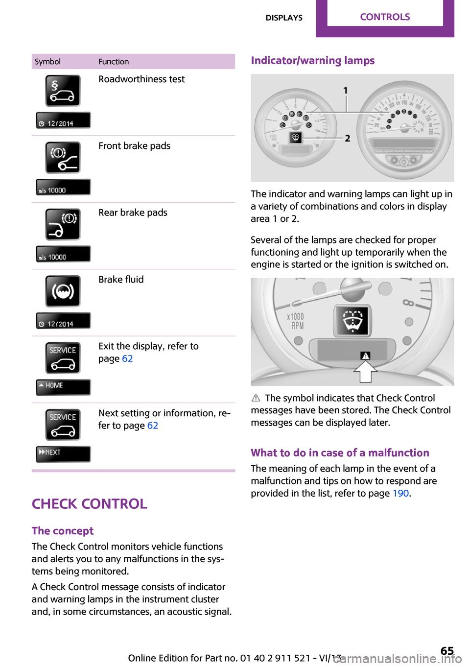
SymbolFunctionRoadworthiness testFront brake padsRear brake padsBrake fluidExit the display, refer to
page 62Next setting or information, re‐
fer to page 62
Check Control
The concept
The Check Control monitors vehicle functions
and alerts you to any malfunctions in the sys‐
tems being monitored.
A Check Control message consists of indicator
and warning lamps in the instrument cluster
and, in some circumstances, an acoustic signal.
Indicator/warning lamps
The indicator and warning lamps can light up in
a variety of combinations and colors in display
area 1 or 2.
Several of the lamps are checked for proper
functioning and light up temporarily when the
engine is started or the ignition is switched on.
The symbol indicates that Check Control
messages have been stored. The Check Control
messages can be displayed later.
What to do in case of a malfunction
The meaning of each lamp in the event of a
malfunction and tips on how to respond are
provided in the list, refer to page 190.
Seite 65DisplaysControls65
Online Edition for Part no. 01 40 2 911 521 - VI/13
Page 66 of 218

Hiding Check Control messages
Press the button on the turn indicator lever.
Some Check Control messages are displayed
continuously and are not cleared until the mal‐
function is eliminated. If several malfunctions
occur at once, the messages are displayed con‐
secutively.
Other Check Control messages are hidden au‐
tomatically after approx. 20 seconds. However,
they are stored and can be displayed again
later.
Viewing stored Check Control messages
The stored Check Control messages can only be
displayed while the driver's door is closed.
1.Press the button on the turn indicator lever
repeatedly until "SET/INFO" is displayed.2.Press and hold the button until the display
changes.3.Press the button repeatedly until the corre‐
sponding symbol and "CHECK INFO" ap‐
pear on the display.4.Press and hold the button.
If there is no Check Control message, this is
indicated by "CHECK OK“.
If a Check Control message has been
stored, the corresponding message is dis‐
played.5.Press the button to check for other mes‐
sages.Seite 66ControlsDisplays66
Online Edition for Part no. 01 40 2 911 521 - VI/13
Page 68 of 218
When the daytime running lights are activated,
the low beams are always switched on in
switch position 3 when the ignition is switched
on.
The exterior lighting goes out automatically af‐
ter the vehicle is switched off.
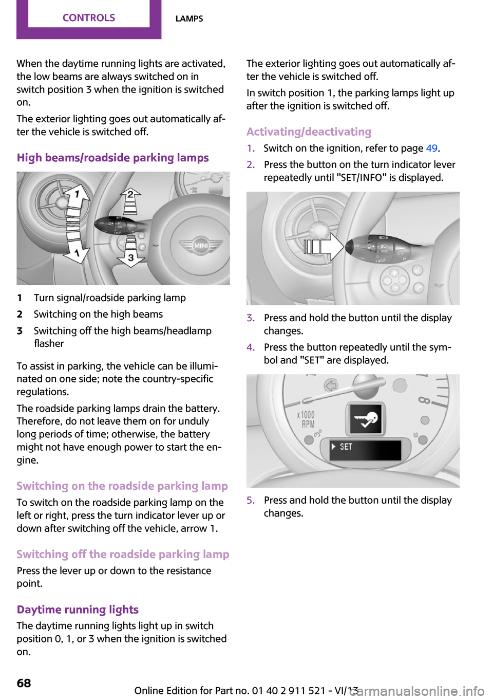
High beams/roadside parking lamps1Turn signal/roadside parking lamp2Switching on the high beams3Switching off the high beams/headlamp
flasher
To assist in parking, the vehicle can be illumi‐
nated on one side; note the country-specific
regulations.
The roadside parking lamps drain the battery.
Therefore, do not leave them on for unduly
long periods of time; otherwise, the battery
might not have enough power to start the en‐
gine.
Switching on the roadside parking lamp
To switch on the roadside parking lamp on the
left or right, press the turn indicator lever up or
down after switching off the vehicle, arrow 1.
Switching off the roadside parking lamp
Press the lever up or down to the resistance
point.
Daytime running lights
The daytime running lights light up in switch
position 0, 1, or 3 when the ignition is switched
on.
The exterior lighting goes out automatically af‐
ter the vehicle is switched off.
In switch position 1, the parking lamps light up
after the ignition is switched off.
Activating/deactivating1.Switch on the ignition, refer to page 49.2.Press the button on the turn indicator lever
repeatedly until "SET/INFO" is displayed.3.Press and hold the button until the display
changes.4.Press the button repeatedly until the sym‐
bol and "SET" are displayed.5.Press and hold the button until the display
changes.Seite 68ControlsLamps68
Online Edition for Part no. 01 40 2 911 521 - VI/13
Page 69 of 218
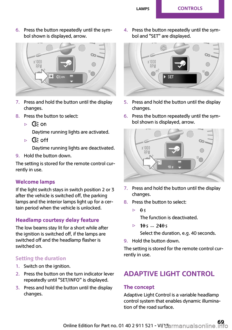
6.Press the button repeatedly until the sym‐
bol shown is displayed, arrow.7.Press and hold the button until the display
changes.8.Press the button to select:▷
Daytime running lights are activated.▷
Daytime running lights are deactivated.9.Hold the button down.
The setting is stored for the remote control cur‐
rently in use.
Welcome lamps If the light switch stays in switch position 2 or 3
after the vehicle is switched off, the parking
lamps and the interior lamps light up for a cer‐
tain period when the vehicle is unlocked.
Headlamp courtesy delay feature The low beams stay lit for a short while after
the ignition is switched off, if the lamps are
switched off and the headlamp flasher is
switched on.
Setting the duration
1.Switch on the ignition.2.Press the button on the turn indicator lever
repeatedly until "SET/INFO" is displayed.3.Press and hold the button until the display
changes.4.Press the button repeatedly until the sym‐
bol and "SET" are displayed.5.Press and hold the button until the display
changes.6.Press the button repeatedly until the sym‐
bol shown is displayed, arrow.7.Press and hold the button until the display
changes.8.Press the button to select:▷
The function is deactivated.▷ ...
Select the duration, e.g. 40 seconds.9.Hold the button down.
The setting is stored for the remote control cur‐
rently in use.
Adaptive Light Control
The concept
Adaptive Light Control is a variable headlamp
control system that enables dynamic illumina‐
tion of the road surface.
Seite 69LampsControls69
Online Edition for Part no. 01 40 2 911 521 - VI/13
Page 76 of 218
Do not initialize the system when driving with
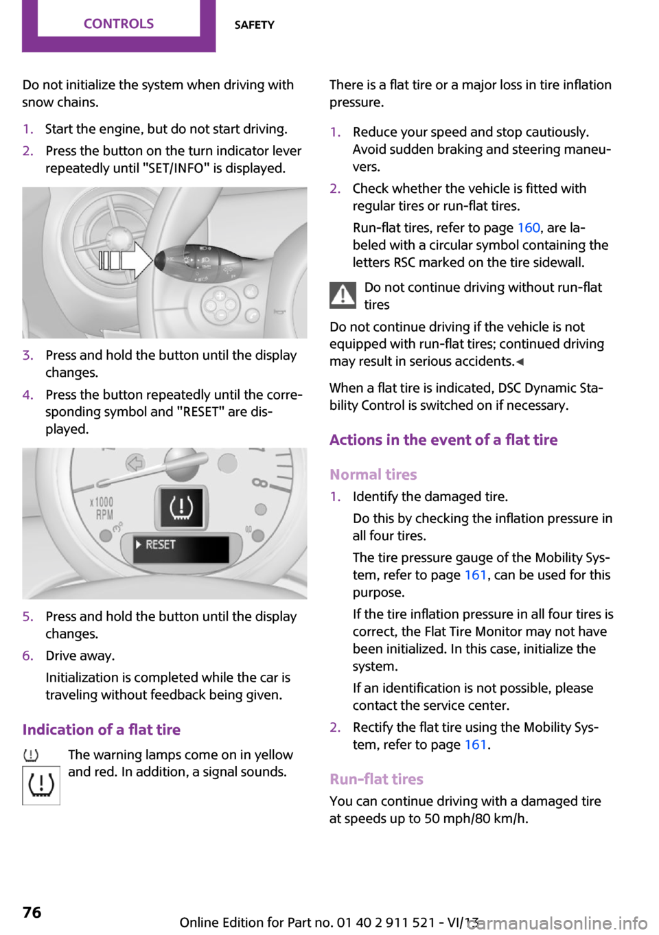
snow chains.1.Start the engine, but do not start driving.2.Press the button on the turn indicator lever
repeatedly until "SET/INFO" is displayed.3.Press and hold the button until the display
changes.4.Press the button repeatedly until the corre‐
sponding symbol and "RESET" are dis‐
played.5.Press and hold the button until the display
changes.6.Drive away.
Initialization is completed while the car is
traveling without feedback being given.
Indication of a flat tire
The warning lamps come on in yellow
and red. In addition, a signal sounds.
There is a flat tire or a major loss in tire inflation
pressure.1.Reduce your speed and stop cautiously.
Avoid sudden braking and steering maneu‐
vers.2.Check whether the vehicle is fitted with
regular tires or run-flat tires.
Run-flat tires, refer to page 160, are la‐
beled with a circular symbol containing the
letters RSC marked on the tire sidewall.
Do not continue driving without run-flat
tires
Do not continue driving if the vehicle is not
equipped with run-flat tires; continued driving
may result in serious accidents. ◀
When a flat tire is indicated, DSC Dynamic Sta‐
bility Control is switched on if necessary.
Actions in the event of a flat tire
Normal tires
1.Identify the damaged tire.
Do this by checking the inflation pressure in
all four tires.
The tire pressure gauge of the Mobility Sys‐
tem, refer to page 161, can be used for this
purpose.
If the tire inflation pressure in all four tires is
correct, the Flat Tire Monitor may not have
been initialized. In this case, initialize the
system.
If an identification is not possible, please
contact the service center.2.Rectify the flat tire using the Mobility Sys‐
tem, refer to page 161.
Run-flat tires
You can continue driving with a damaged tire
at speeds up to 50 mph/80 km/h.
Seite 76ControlsSafety76
Online Edition for Part no. 01 40 2 911 521 - VI/13
Page 78 of 218
▷When the TPM is disturbed by other sys‐
tems or devices with the same radio fre‐
quency.
Resetting the system
Reset the system after each correction of the
tire inflation pressure and after every tire or
wheel change.
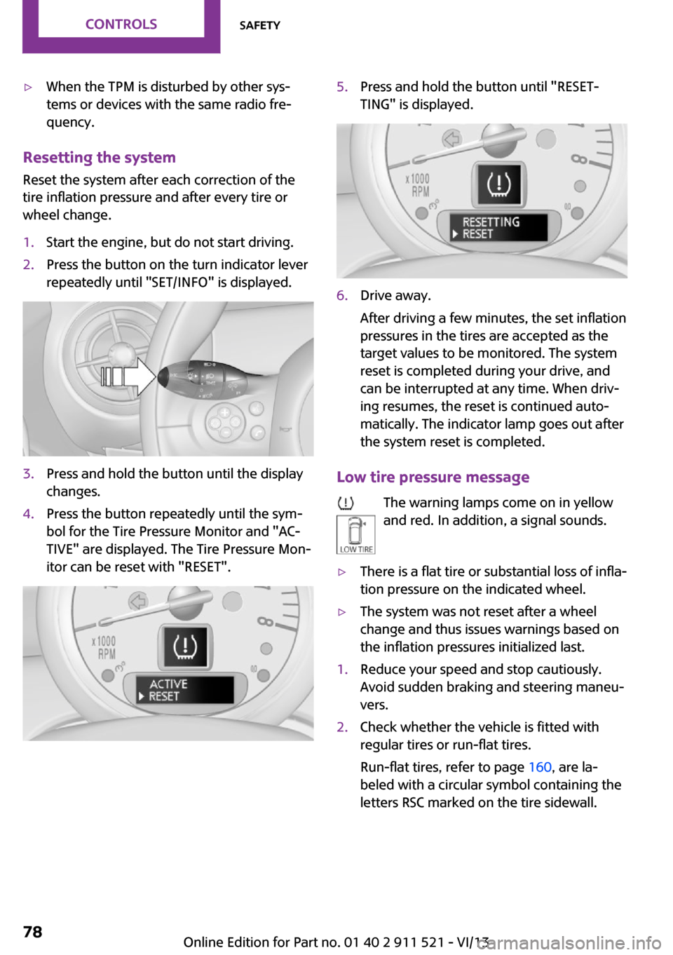
1.Start the engine, but do not start driving.2.Press the button on the turn indicator lever
repeatedly until "SET/INFO" is displayed.3.Press and hold the button until the display
changes.4.Press the button repeatedly until the sym‐
bol for the Tire Pressure Monitor and "AC‐
TIVE" are displayed. The Tire Pressure Mon‐
itor can be reset with "RESET".5.Press and hold the button until "RESET‐
TING" is displayed.6.Drive away.
After driving a few minutes, the set inflation
pressures in the tires are accepted as the
target values to be monitored. The system
reset is completed during your drive, and
can be interrupted at any time. When driv‐
ing resumes, the reset is continued auto‐
matically. The indicator lamp goes out after
the system reset is completed.
Low tire pressure message
The warning lamps come on in yellow
and red. In addition, a signal sounds.
▷There is a flat tire or substantial loss of infla‐
tion pressure on the indicated wheel.▷The system was not reset after a wheel
change and thus issues warnings based on
the inflation pressures initialized last.1.Reduce your speed and stop cautiously.
Avoid sudden braking and steering maneu‐
vers.2.Check whether the vehicle is fitted with
regular tires or run-flat tires.
Run-flat tires, refer to page 160, are la‐
beled with a circular symbol containing the
letters RSC marked on the tire sidewall.Seite 78ControlsSafety78
Online Edition for Part no. 01 40 2 911 521 - VI/13
Page 80 of 218

Final tire failure
Vibrations or loud noises while driving
can indicate the final failure of the tire. Reduce
speed and stop; otherwise, pieces of the tire
could come loose and cause an accident. Do
not continue driving, and contact your service
center. ◀
Malfunction The small warning lamp flashes in yel‐
low and then lights up continuously; the larger warning lamp comes on in yel‐
low.
No flat tire can be detected.
Display in the following situations:▷A wheel without TPM electronics is
mounted:
Have the system checked by the service
center if necessary.▷Malfunction:
Have the system checked.▷TPM could not be fully reset; reset the sys‐
tem again.
The small warning lamp flashes in yel‐
low and then lights up continuously; the
larger warning lamp comes on in yel‐
low.
No flat tire can be detected.
Display in the following situation:
▷Disturbance by other systems or devices
with the same radio frequency
After leaving the area of the disturbance,
the system automatically becomes active
again.
Declaration according to NHTSA/FMVSS
138 Tire Pressure Monitoring Systems
Each tire, including the spare (if provided)
should be checked monthly when cold and in‐
flated to the inflation pressure recommended
by the vehicle manufacturer on the vehicle
placard or tire inflation pressure label (If your
vehicle has tires of a different size than the size
indicated on the vehicle placard or tire inflation
pressure label, you should determine the
proper tire inflation pressure for those tires.).
As an added safety feature, your vehicle has
been equipped with a tire pressure monitoring
system (TPMS) that illuminates a low tire pres‐
sure telltale when one or more of your tires is
significantly under-inflated. Accordingly, when
the low tire pressure telltale illuminates, you
should stop and check your tires as soon as
possible, and inflate them to the proper pres‐
sure. Driving on a significantly under-inflated
tire causes the tire to overheat and can lead to
tire failure. Under-inflation also reduces fuel ef‐
ficiency and tire tread life, and may affect the
vehicle's handling and stopping ability.
Please note that the TPMS is not a substitute for
proper tire maintenance, and it is the driver's
responsibility to maintain correct tire pressure,
even if under-inflation has not reached the
level to trigger illumination of the TPMS low tire
pressure telltale.
Your vehicle has also been equipped with a
TPMS malfunction indicator to indicate when
the system is not operating properly. The TPMS
malfunction indicator is combined with the low
tire pressure telltale. When the system detects
a malfunction, the telltale will flash for approxi‐
mately one minute and then remain continu‐
ously illuminated. This sequence will continue
upon subsequent vehicle startups as long as
the malfunction exists. When the malfunction
indicator is illuminated, the system may not be
able to detect or signal low tire pressure as in‐
tended. TPMS malfunctions may occur for a va‐
riety of reasons, including the installation of re‐
placement or alternate tires or wheels on the
vehicle that prevent the TPMS from functioning
properly. Always check the TPMS malfunction
telltale after replacing one or more tires or
wheels on your vehicle to ensure that the re‐
placement or alternate tires and wheels allow
the TPMS to continue to function properly.Seite 80ControlsSafety80
Online Edition for Part no. 01 40 2 911 521 - VI/13
Page 82 of 218
appears in the tachometer. DSC is deactivated.
Intervening measures to stabilize the vehicle
and give it forward momentum are no longer
executed.
When driving with snow chains or to rock the
vehicle free of snow, it may be useful to deacti‐
vate DSC temporarily.
To increase vehicle stability, activate DSC again
as soon as possible.
Activating DSC
Press the switch again; the DSC indicator lamps
in the display elements go out.
Indicator/warning lamps The indicator lamp in the tachometer
flashes: DSC is controlling the drive
forces and brake forces.
The indicator lamp lights up: DSC and DTC has
failed.
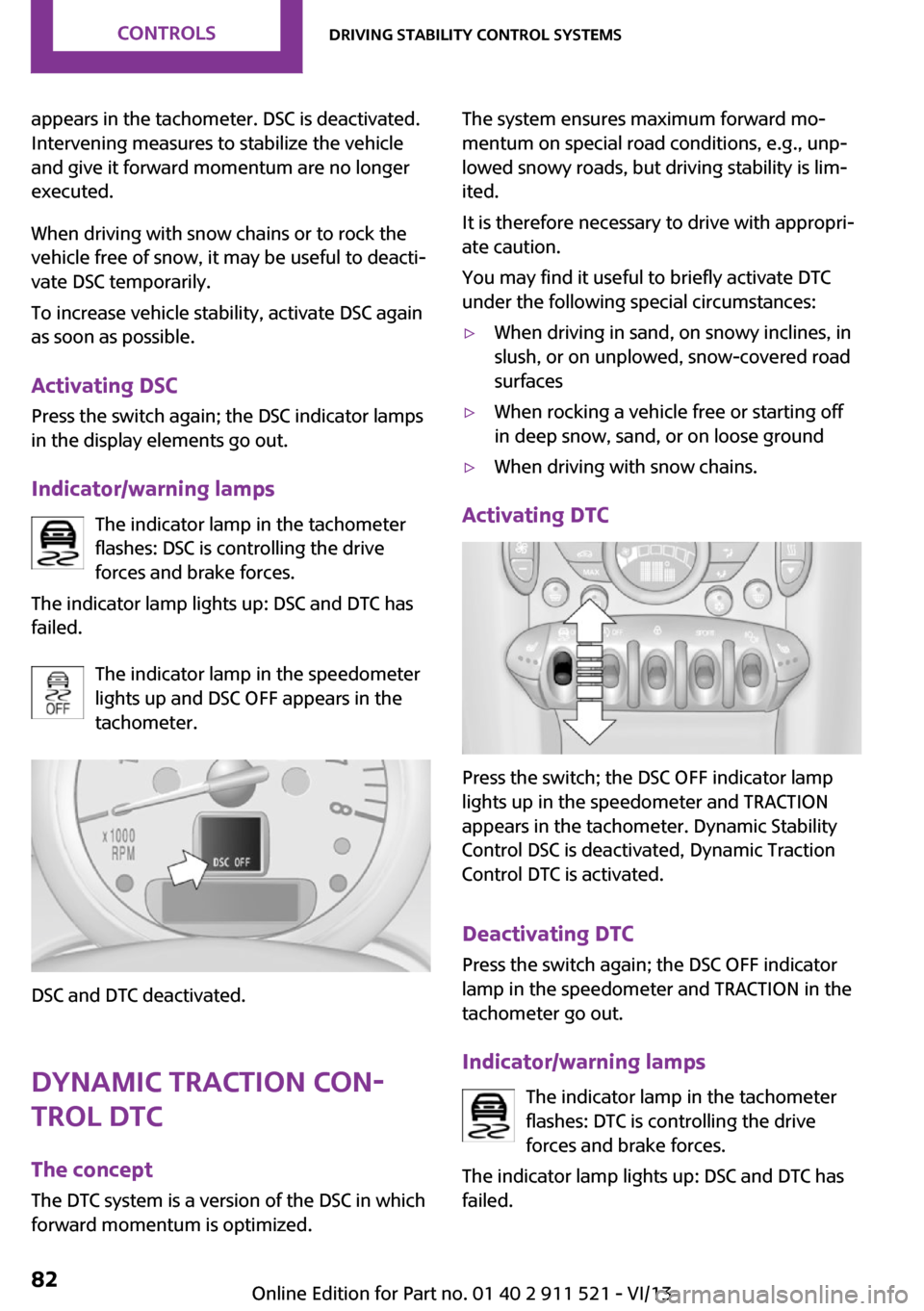
The indicator lamp in the speedometer
lights up and DSC OFF appears in the
tachometer.
DSC and DTC deactivated.
Dynamic Traction Con‐
trol DTC
The concept
The DTC system is a version of the DSC in which
forward momentum is optimized.
The system ensures maximum forward mo‐
mentum on special road conditions, e.g., unp‐
lowed snowy roads, but driving stability is lim‐
ited.
It is therefore necessary to drive with appropri‐
ate caution.
You may find it useful to briefly activate DTC
under the following special circumstances:▷When driving in sand, on snowy inclines, in
slush, or on unplowed, snow-covered road
surfaces▷When rocking a vehicle free or starting off
in deep snow, sand, or on loose ground▷When driving with snow chains.
Activating DTC
Press the switch; the DSC OFF indicator lamp
lights up in the speedometer and TRACTION
appears in the tachometer. Dynamic Stability
Control DSC is deactivated, Dynamic Traction
Control DTC is activated.
Deactivating DTC Press the switch again; the DSC OFF indicator
lamp in the speedometer and TRACTION in the
tachometer go out.
Indicator/warning lamps The indicator lamp in the tachometer
flashes: DTC is controlling the drive
forces and brake forces.
The indicator lamp lights up: DSC and DTC has
failed.
Seite 82ControlsDriving stability control systems82
Online Edition for Part no. 01 40 2 911 521 - VI/13