diagnostic connector MITSUBISHI 380 2005 Workshop Manual
[x] Cancel search | Manufacturer: MITSUBISHI, Model Year: 2005, Model line: 380, Model: MITSUBISHI 380 2005Pages: 1500, PDF Size: 47.87 MB
Page 761 of 1500
AUTO A/C DIAGNOSIS
HEATER, AIR CONDITIONING AND VENTILATION55-60
DTC U1111: Multi-Center Display Unit Time-out
If DTC U1111 is set in the A/C-ECU, diagnose the
CAN main bus line.
Whenever the ECU is replaced, ensure that the
communication circuit is normal.
.
TROUBLE JUDGMENT
The A/C-ECU receives signals from the multi-center
display unit. If the ECU cannot receive the signal
r e l a t e d t o t h e m u l t i - c e n t e r d i s p l a y u n i t , D T C U 1111
will be set.
.
TECHNICAL DESCRIPTION (COMMENT)
Current trouble
Connector(s) or wiring harness in the CAN bus
lines between the A/C-ECU and the multi-center
display unit, the power supply system to the dis-
play unit, the display unit itself, or the A/C-ECU
may be defective.
Past trouble
W h e n D T C U 1111 i s s e t a s a p a s t t r o u b l e , c a r r y
out diagnosis with particular emphasis on con-
nector(s) or wiring harness in the CAN bus lines
between the A/C-ECU and the multi-center dis-
play unit, the power supply system to the display unit. If the connectors and wiring are normal, and
obviously the ECU or the multi-center display is
the cause of the trouble, replace the ECU or the
multi-center display. If in doubt, do not replace
the ECU or the display unit.
NOTE: For a past trouble, you cannot find it by
the diagnostic tool CAN bus diagnostics even if
there is a failure in the CAN bus lines. In this
case, refer to GROUP 00, How to Use Trouble-
shooting/Inspection Service Points
How to
Cope with Intermittent Malfunctions P.00-14.)
and check the CAN bus lines. You can narrow
down the possible cause of the trouble by refer-
ring to the DTC, which is set regarding the CAN
communication-linked ECUs (Refer to GROUP
54C
Explanation about the diagnostic tool CAN
bus diagnostics P.54C-6).
.
TROUBLESHOOTING HINTS
Malfunction of multi-center display unit
Malfunction of the A/C-ECU
Damaged harness wires and connectors
Refer to component locations GROUP-70
Refer to configuration diagrams GROUP-80
Refer to circuit diagrams GROUP-90
DIAGNOSIS
Required Special Tools:
: Diagnostic Tool (MUT-III Sub Assembly)
MB991824: Vehicle Communication Interface (V.C.I.)
MB991827: MUT-III USB Cable
MB991910: MUT-III Main Harness A (Vehicles with CAN
communication system)
Page 762 of 1500

AUTO A/C DIAGNOSIS
HEATER, AIR CONDITIONING AND VENTILATION55-61
STEP 1. Using diagnostic tool , diagnose the CAN bus line.
To prevent damage to diagnostic tool (MUT-III), always turn
the ignition switch to the "LOCK" (OFF) position before
connecting or disconnecting diagnostic tool (MUT-III).
(1) Connect diagnostic tool to the data link connector.
(2) Turn the ignition switch to the "ON" position.
(3) Diagnose the CAN bus line.
(4) Turn the ignition switch to the "LOCK" (OFF) position.
Q: Is the CAN bus line found to be normal?
YES : Go to Step 2.
NO : Repair the CAN bus line (Refer to GROUP 54C,
Diagnosis P.54C-15).
STEP 2. Using diagnostic tool , read the Electronic control
unit diagnostic trouble code.
Check that the multi-center display unit sets a DTC.
(1) Turn the ignition switch to the "ON" position.
(2) Check for the DTC related to the multi-center display unit.
(3) Turn the ignition switch to the "LOCK" (OFF) position.
Q: Is the check result satisfactory?
YES : Refer to GROUP 54A, multi-center display unit
Diagnosis P.54A-254.
NO : Go to Step 3.
Page 765 of 1500
AUTO A/C DIAGNOSIS
HEATER, AIR CONDITIONING AND VENTILATION55-64
DTC U1120: Failure Information on Electronic control unit (Related to Engine)
If DTC U1120 is set in the A/C-ECU, diagnose the
CAN main bus line.
Whenever the ECU is replaced, ensure that the
communication circuit is normal.
The engine control system- related DTC may be
set when DTC U1120 is set. (For details refer to
GROUP 00, Intersystem Affiliated DTC Reference
Ta b l e P.00-17.) Diagnose the engine control sys-
tem first when the engine control system- related
DTC is set.
.
TROUBLE JUDGMENT
The A/C-ECU receives engine control sys-
tem-related signal from the Electronic control unit by
the CAN bus lines. If a fail-safe related data is con-
tained in the signal from the Electronic control unit,
DTC U1120 will be stored.
.
TECHNICAL DESCRIPTION (COMMENT)
Current trouble
The wiring harness wire or connectors may have
loose, corroded, or damage terminals, or termi-
nals pushed back in the connector, the Electronic
control unit, or the A/C-ECU may be defective.Past trouble
If DTC U1120 is stored as a past trouble, carry
out diagnosis with particular emphasis on wiring
and connector(s) in the CAN bus line between
the A/C-ECU and the Electronic control unit, and
the power supply system to the Electronic control
unit. If the connectors and wiring are normal, and
obviously the ECU is the cause of the trouble,
replace the ECU. If in doubt, do not replace the
ECU.
NOTE: For a past trouble, you cannot find it by
the diagnostic tool CAN bus diagnostics even if
there is a failure in CAN bus lines. In this case,
refer to GROUP 00, How to Use Troubleshoot-
ing/Inspection Service Points
How to Cope with
Intermittent Malfunctions P.00-14.) and check the
CAN bus lines. You can narrow down the possi-
ble cause of the trouble by referring to the DTC,
which is set regarding the CAN communica-
tion-linked ECUs (Refer to GROUP 54C
Expla-
nation about the diagnostic tool CAN bus
diagnostics P.54C-6).
.
TROUBLESHOOTING HINTS
Malfunction of the A/C-ECU.
Malfunction of the Electronic control unit.
Refer to component locations GROUP-70
Refer to configuration diagrams GROUP-80
Refer to circuit diagrams GROUP-90
DIAGNOSIS
Required Special Tool:
: Diagnostic Tool (MUT-III Sub Assembly)
MB991824: Vehicle Communication Interface (V.C.I.)
MB991827: MUT-III USB Cable
MB991910: MUT-III Main Harness A (Vehicles with CAN
communication system)
Page 766 of 1500
AUTO A/C DIAGNOSIS
HEATER, AIR CONDITIONING AND VENTILATION55-65
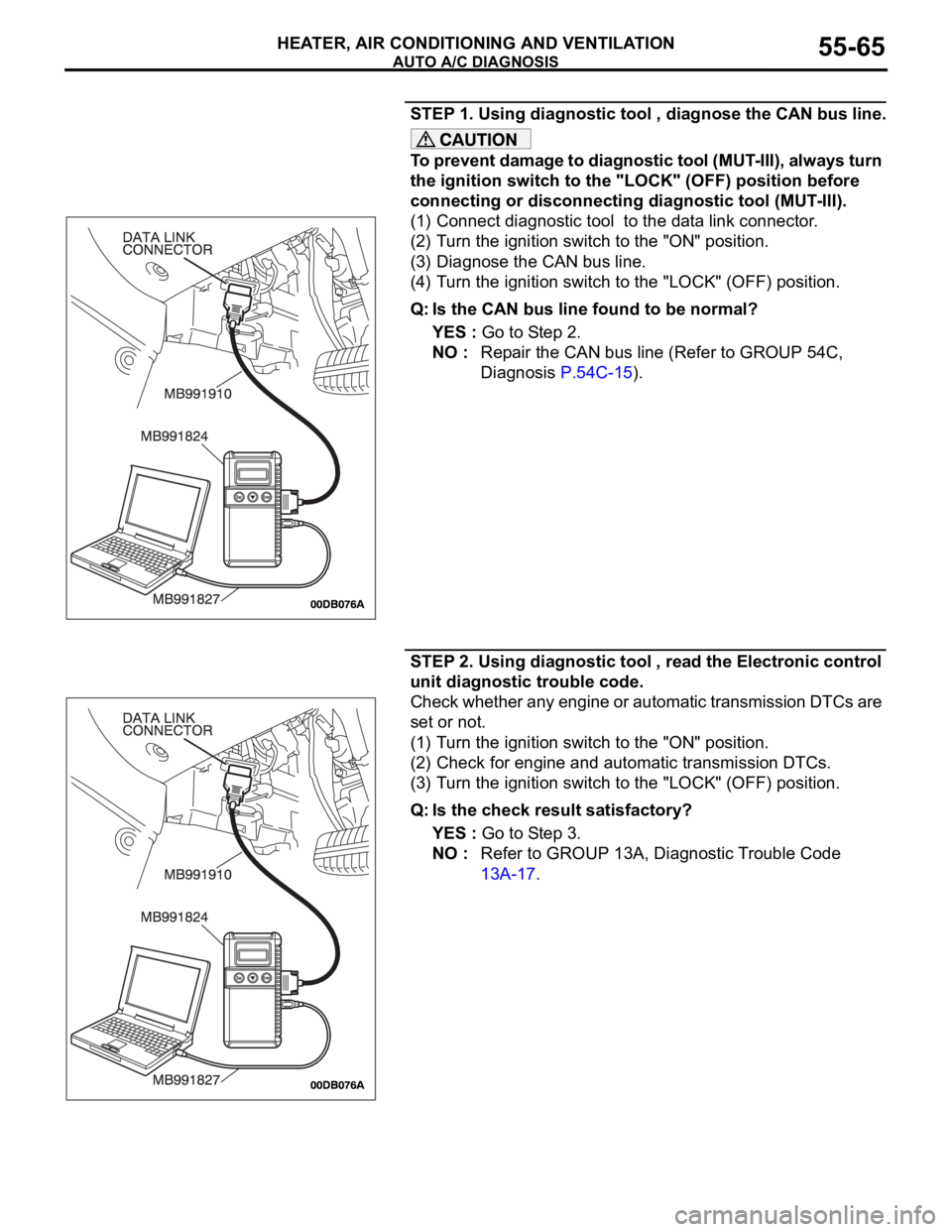
STEP 1. Using diagnostic tool , diagnose the CAN bus line.
To prevent damage to diagnostic tool (MUT-III), always turn
the ignition switch to the "LOCK" (OFF) position before
connecting or disconnecting diagnostic tool (MUT-III).
(1) Connect diagnostic tool to the data link connector.
(2) Turn the ignition switch to the "ON" position.
(3) Diagnose the CAN bus line.
(4) Turn the ignition switch to the "LOCK" (OFF) position.
Q: Is the CAN bus line found to be normal?
YES : Go to Step 2.
NO : Repair the CAN bus line (Refer to GROUP 54C,
Diagnosis P.54C-15).
STEP 2. Using diagnostic tool , read the Electronic control
unit diagnostic trouble code.
Check whether any engine or automatic transmission DTCs are
set or not.
(1) Turn the ignition switch to the "ON" position.
(2) Check for engine and automatic transmission DTCs.
(3) Turn the ignition switch to the "LOCK" (OFF) position.
Q: Is the check result satisfactory?
YES : Go to Step 3.
NO : Refer to GROUP 13A, Diagnostic Trouble Code
13A-17.
Page 767 of 1500
AUTO A/C DIAGNOSIS
HEATER, AIR CONDITIONING AND VENTILATION55-66
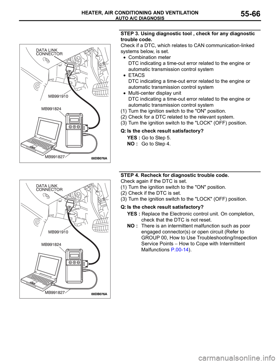
STEP 3. Using diagnostic tool , check for any diagnostic
trouble code.
Check if a DTC, which relates to CAN communication-linked
systems below, is set.
Combination meter
DTC indicating a time-out error related to the engine or
automatic transmission control system
ETACS
DTC indicating a time-out error related to the engine or
automatic transmission control system
Multi-center display unit
DTC indicating a time-out error related to the engine or
automatic transmission control system
(1) Turn the ignition switch to the "ON" position.
(2) Check for a DTC related to the relevant system.
(3) Turn the ignition switch to the "LOCK" (OFF) position.
Q: Is the check result satisfactory?
YES : Go to Step 5.
NO : Go to Step 4.
STEP 4. Recheck for diagnostic trouble code.
Check again if the DTC is set.
(1) Turn the ignition switch to the "ON" position.
(2) Check if the DTC is set.
(3) Turn the ignition switch to the "LOCK" (OFF) position.
Q: Is the check result satisfactory?
YES : Replace the Electronic control unit. On completion,
check that the DTC is not reset.
NO : There is an intermittent malfunction such as poor
engaged connector(s) or open circuit (Refer to
GROUP 00, How to Use Troubleshooting/Inspection
Service Points
How to Cope with Intermittent
Malfunctions P.00-14).
Page 777 of 1500
AUTO A/C DIAGNOSIS
HEATER, AIR CONDITIONING AND VENTILATION55-76
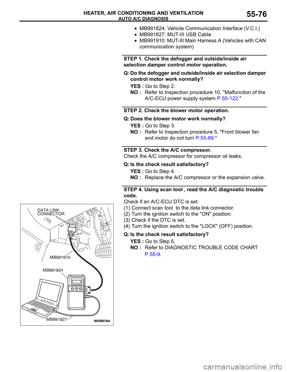
MB991824: Vehicle Communication Interface (V.C.I.)
MB991827: MUT-III USB Cable
MB991910: MUT-III Main Harness A (Vehicles with CAN
communication system)
STEP 1. Check the defogger and outside/inside air
selection damper control motor operation.
Q: Do the defogger and outside/inside air selection damper
control motor work normally?
YES : Go to Step 2.
NO : Refer to Inspection procedure 10, "Malfunction of the
A/C-ECU power supply system P.55-122."
STEP 2. Check the blower motor operation.
Q: Does the blower motor work normally?
YES : Go to Step 3.
NO : Refer to Inspection procedure 5, "Front blower fan
and motor do not turn P.55-89."
STEP 3. Check the A/C compressor.
Check the A/C compressor for compressor oil leaks.
Q: Is the check result satisfactory?
YES : Go to Step 4.
NO : Replace the A/C compressor or the expansion valve.
STEP 4. Using scan tool , read the A/C diagnostic trouble
code.
Check if an A/C-ECU DTC is set.
(1) Connect scan tool to the data link connector.
(2) Turn the ignition switch to the "ON" position.
(3) Check if the DTC is set.
(4) Turn the ignition switch to the "LOCK" (OFF) position.
Q: Is the check result satisfactory?
YES : Go to Step 5.
NO : Refer to DIAGNOSTIC TROUBLE CODE CHART
P.55-9.
Page 805 of 1500
AUTO A/C DIAGNOSIS
HEATER, AIR CONDITIONING AND VENTILATION55-104
INSPECTION PROCEDURE 7: The A/C Indicator Flashes.
.
TECHNICAL DESCRIPTION (COMMENT)
If the A/C indicator flashes, inadequate refrigerant
quantity, the ambient air temperature sensor circuit
or the A/C pressure sensor circuit is suspected.
.
TROUBLESHOOTING HINTS
Malfunction of the A/C pressure sensor
Malfunction of the ambient air temperature sen-
sor
Malfunction of the A/C-ECU
Refer to component locations GROUP-70
Refer to configuration diagrams GROUP-80
Refer to circuit diagrams GROUP-90
DIAGNOSIS
Required Special Tools:
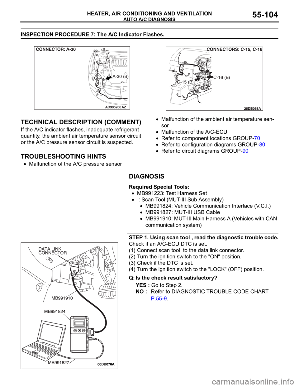
MB991223: Test Harness Set
: Scan Tool (MUT-III Sub Assembly)
MB991824: Vehicle Communication Interface (V.C.I.)
MB991827: MUT-III USB Cable
MB991910: MUT-III Main Harness A (Vehicles with CAN
communication system)
STEP 1. Using scan tool , read the diagnostic trouble code.
Check if an A/C-ECU DTC is set.
(1) Connect scan tool to the data link connector.
(2) Turn the ignition switch to the "ON" position.
(3) Check if the DTC is set.
(4) Turn the ignition switch to the "LOCK" (OFF) position.
Q: Is the check result satisfactory?
YES : Go to Step 2.
NO : Refer to DIAGNOSTIC TROUBLE CODE CHART
P.55-9.
Page 830 of 1500
AUTO A/C DIAGNOSIS
HEATER, AIR CONDITIONING AND VENTILATION55-129
DIAGNOSIS
Required Special Tools:
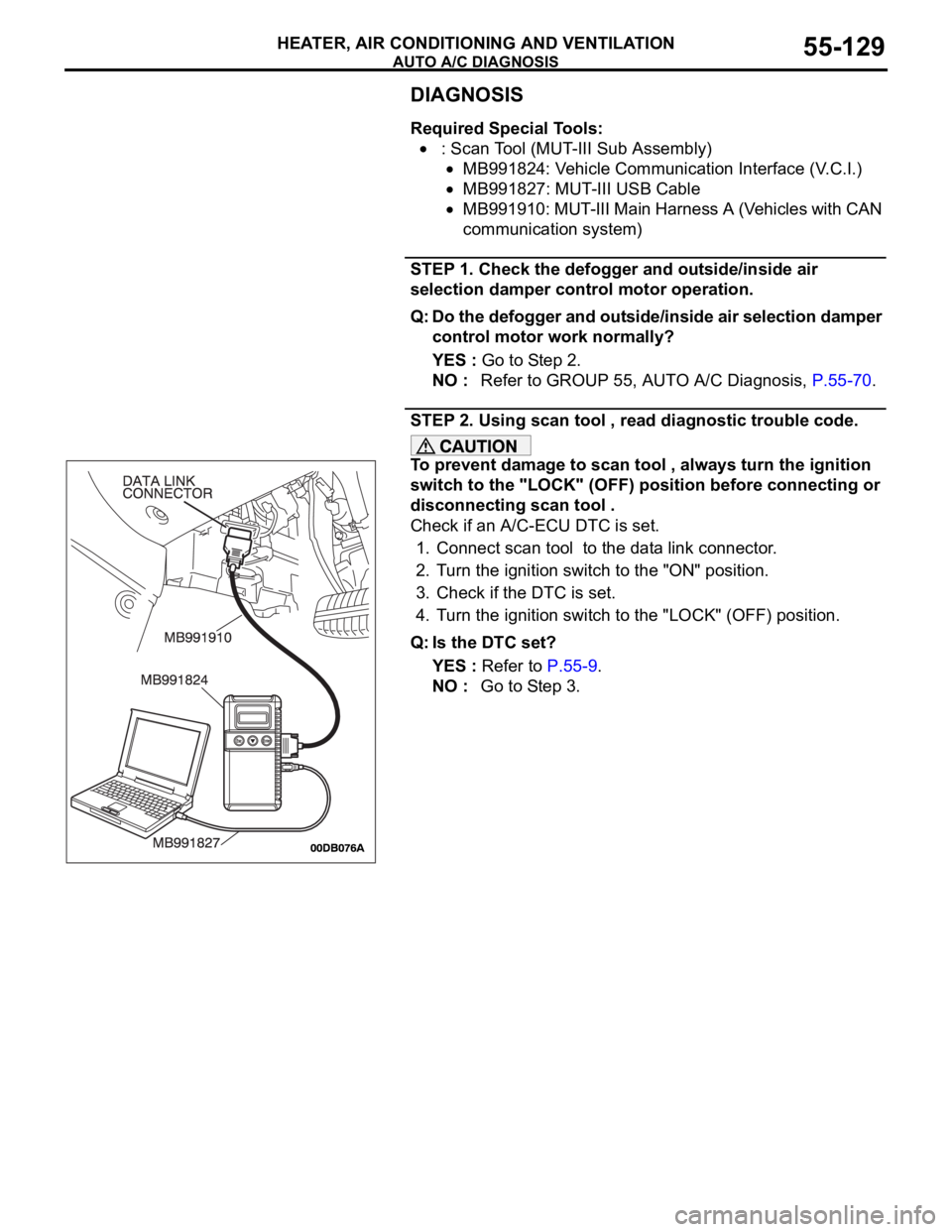
: Scan Tool (MUT-III Sub Assembly)
MB991824: Vehicle Communication Interface (V.C.I.)
MB991827: MUT-III USB Cable
MB991910: MUT-III Main Harness A (Vehicles with CAN
communication system)
STEP 1. Check the defogger and outside/inside air
selection damper control motor operation.
Q: Do the defogger and outside/inside air selection damper
control motor work normally?
YES : Go to Step 2.
NO : Refer to GROUP 55, AUTO A/C Diagnosis, P.55-70.
STEP 2. Using scan tool , read diagnostic trouble code.
To prevent damage to scan tool , always turn the ignition
switch to the "LOCK" (OFF) position before connecting or
disconnecting scan tool .
Check if an A/C-ECU DTC is set.
1. Connect scan tool to the data link connector.
2. Turn the ignition switch to the "ON" position.
3. Check if the DTC is set.
4. Turn the ignition switch to the "LOCK" (OFF) position.
Q: Is the DTC set?
YES : Refer to P.55-9.
NO : Go to Step 3.
Page 983 of 1500
CHARGING SYSTEM
ENGINE ELECTRICAL16-6
SPECIAL TOOLM1161000600486
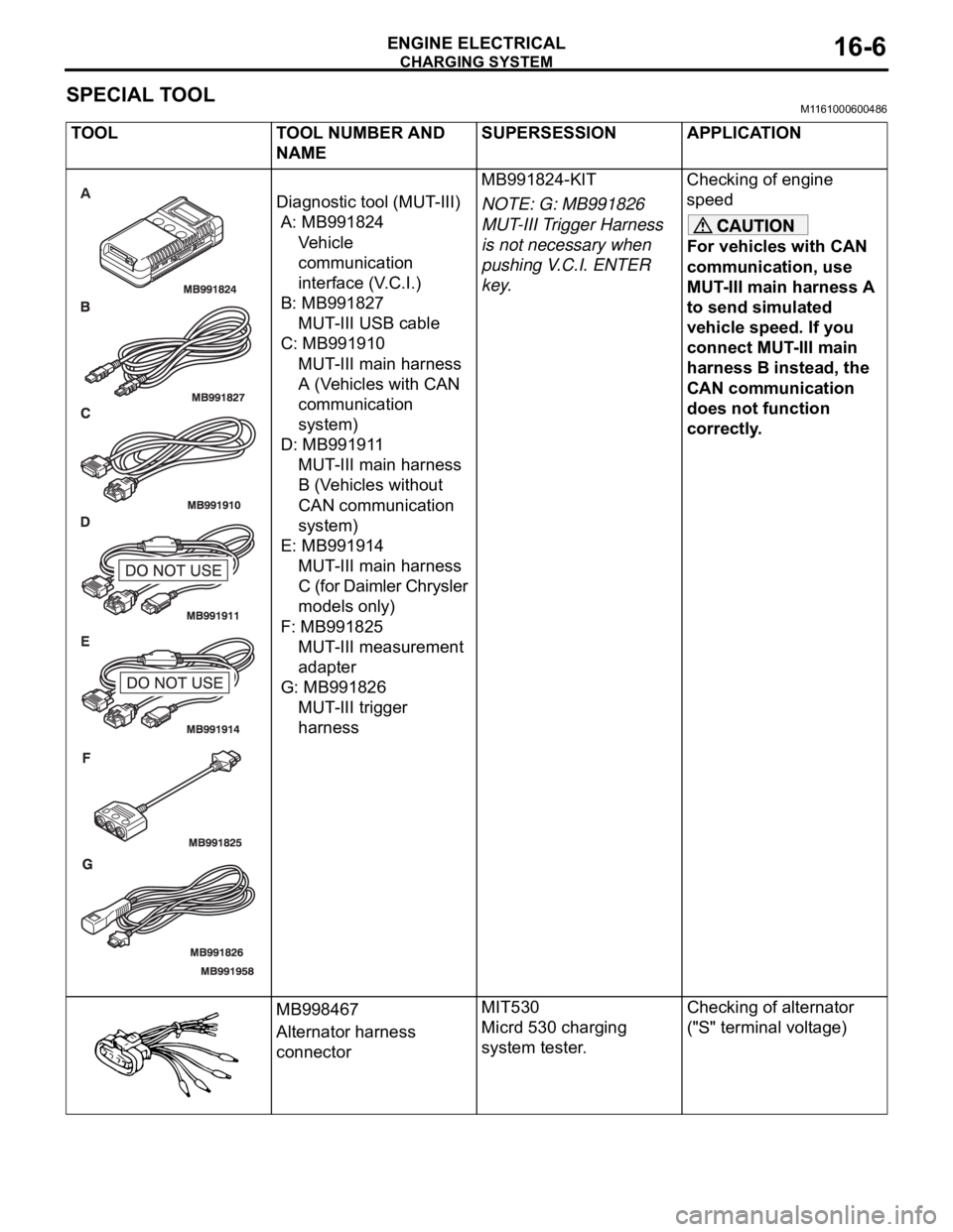
TOOL TOOL NUMBER AND
NAMESUPERSESSION APPLICATION
Diagnostic tool (MUT-III)
A: MB991824
Ve h i c l e
communication
interface (V.C.I.)
B: MB991827
MUT-III USB cable
C: MB991910
MUT-III main harness
A (Vehicles with CAN
communication
system)
D: MB991911
MUT-III main harness
B (Vehicles without
CAN communication
system)
E: MB991914
MUT-III main harness
C (for Daimler Chrysler
models only)
F: MB991825
MUT-III measurement
adapter
G: MB991826
MUT-III trigger
harnessMB991824-KIT
NOTE: G: MB991826
MUT-III Trigger Harness
is not necessary when
pushing V.C.I. ENTER
key.Checking of engine
speed
For vehicles with CAN
communication, use
MUT-III main harness A
to send simulated
vehicle speed. If you
connect MUT-III main
harness B instead, the
CAN communication
does not function
correctly.
MB998467
Alternator harness
connectorMIT530
Micrd 530 charging
system tester.Checking of alternator
("S" terminal voltage)
Page 987 of 1500
CHARGING SYSTEM
ENGINE ELECTRICAL16-10
REGULATED VOLTAGE TESTM1161001100666
Required Special Tools:
: Diagnostic Tool (MUT-III)
MB991824: V.C.I.
MB991827: MUT-III USB Cable
MB991910: MUT-III Main Harness A
MB998467: Alternator Harness Connector
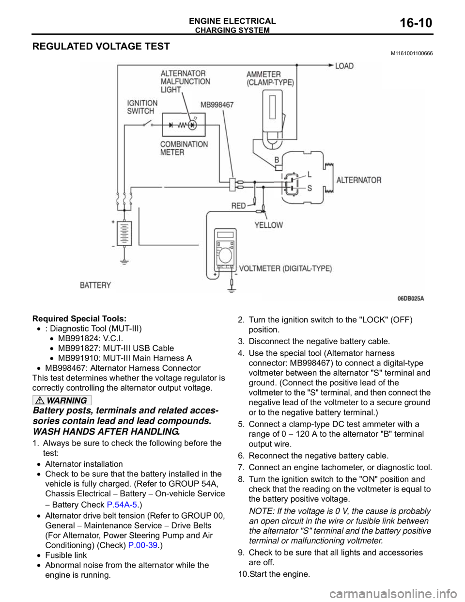
This test determines whether the voltage regulator is
correctly controlling the alternator output voltage.
Battery posts, terminals and related acces-
sories contain lead and lead compounds.
WASH HANDS AFTER HANDLING.
1. Always be sure to check the following before the
test:
Alternator installation
Check to be sure that the battery installed in the
vehicle is fully charged. (Refer to GROUP 54A,
Chassis Electrical
Battery On-vehicle Service
Battery Check P.54A-5.)
Alternator drive belt tension (Refer to GROUP 00,
General
Maintenance Service Drive Belts
(For Alternator, Power Steering Pump and Air
Conditioning) (Check) P.00-39.)
Fusible link
Abnormal noise from the alternator while the
engine is running.2. Turn the ignition switch to the "LOCK" (OFF)
position.
3. Disconnect the negative battery cable.
4. Use the special tool (Alternator harness
connector: MB998467) to connect a digital-type
voltmeter between the alternator "S" terminal and
ground. (Connect the positive lead of the
voltmeter to the "S" terminal, and then connect the
negative lead of the voltmeter to a secure ground
or to the negative battery terminal.)
5. Connect a clamp-type DC test ammeter with a
range of 0
120 A to the alternator "B" terminal
output wire.
6. Reconnect the negative battery cable.
7. Connect an engine tachometer, or diagnostic tool.
8. Turn the ignition switch to the "ON" position and
check that the reading on the voltmeter is equal to
the battery positive voltage.
NOTE: If the voltage is 0 V, the cause is probably
an open circuit in the wire or fusible link between
the alternator "S" terminal and the battery positive
terminal or malfunctioning voltmeter.
9. Check to be sure that all lights and accessories
are off.
10.Start the engine.