ECO mode MITSUBISHI 380 2005 Workshop Manual
[x] Cancel search | Manufacturer: MITSUBISHI, Model Year: 2005, Model line: 380, Model: MITSUBISHI 380 2005Pages: 1500, PDF Size: 47.87 MB
Page 355 of 1500
SYMPTOM PROCEDURES
SIMPLIFIED WIRING SYSTEM (SWS)54B-355
54B
INTERIOR LAMP
GENERAL DESCRIPTION CONCERNING THE INTERIOR LAMPM1549021800236
Refer to circuit diagrams GROUP-90
Refer to configuration diagrams GROUP-80The following ECUs affect the functions and control
of the interior lamps.
Interior lamp control function
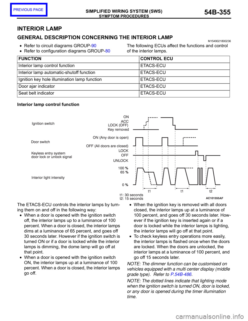
The ETACS-ECU controls the interior lamps by turn-
ing them on and off in the following way:
When a door is opened with the ignition switch
off, the interior lamps up to a luminance of 100
percent. When a door is closed, the interior lamps
dims at a luminance of 65 percent, and goes off
30 seconds later. However if the ignition switch is
turned ON or if a door is locked while the interior
lamps is dimming, the dome lamp will go off at
that point.
When a door is opened with the ignition switch
ON, the interior lamps up at a luminance of 100
percent. When a door is closed, the interior lamps
go off.
When the ignition key is removed with all doors
closed, the interior lamps up at a luminance of
100 percent, and goes off 30 seconds later. How-
ever if the ignition key is inserted again or if a
door is locked while the interior lamps is lighting,
the interior lamps will go off at that point.
To check keyless entry operations more easily,
the interior lamps is flashed once when the doors
are locked. When the doors are unlocked, the
interior lamps at a luminance of 100 percent, and
go off 15 seconds later.
NOTE: The dimmer function can be customised on
vehicles equipped with a multi center display (middle
grade type). Refer to P.54B-486.
NOTE: The dotted lines indicate that lighting mode
when the ignition switch is turned ON, door is locked,
or any door is opened during the timer illumination
time. FUNCTION CONTROL ECU
Interior lamp control function ETACS-ECU
Interior lamp automatic-shutoff function ETACS-ECU
Ignition key hole illumination lamp function ETACS-ECU
Door ajar indicator ETACS-ECU
Seat belt indicator ETACS-ECU
Page 704 of 1500
GENERAL DESCRIPTION
HEATER, AIR CONDITIONING AND VENTILATION55-3
GENERAL DESCRIPTIONM1552000100351
The heater and cooling units are combined in a sin-
gle unit, which, with the mode film damper and flow
rate control valve in the heater unit, reduces ventila-
tion resistance, increases fan power, and decreases
noise.
SAFETY PRECAUTIONS
Wear safety goggles and gloves when servic-
ing the refrigeration system to prevent
severe damage to eyes and hands.
Because R-134a refrigerant is a hydro fluorocarbon
(HFC) which contains hydrogen atoms in place of
chlorine atoms, it will not cause damage to the ozone
layer.
Ozone filters out harmful radiation from the sun. To
assist in protecting the ozone layer, Mitsubishi
Motors Corporation recommends an R-134a refriger-
ant recycling device.
Refrigerant R-134a is transparent and colorless in
both the liquid and vapor state. Since it has a boiling
point of
29.8C (21.64F) at atmospheric pressure,
it will be a vapor at all normal temperatures and pres-
sures. The vapor is heavier than air, non-flammable,
and non-explosive. The following precautions must
be observed when handling R-134a.
Do not heat R-134a above 40C (104.0F) or it
may catch fire and explode.
R-134a evaporates so rapidly at normal atmospheric
pressures and temperatures that it tends to freeze
anything it contacts. For this reason, extreme care
must be taken to prevent any liquid refrigerant from
contacting the skin and especially the eyes. Always
wear safety goggles when servicing the refrigeration
part of the A/C system. Keep a bottle of sterile min-
eral oil handy when working on the refrigeration sys-
tem.1. If any liquid refrigerant gets into your eyes, use a
few drops of mineral oil to wash them out. R-134a
is rapidly absorbed by the oil.
2. Next, splash your eyes with plenty of cold water.
3. Call your doctor immediately even if irritation has
ceased.
Keep R-134a containers upright when charging
the system.
In most instances, moderate heat is required to bring
the pressure of the refrigerant in its container above
the pressure of the system when charging or adding
refrigerant.
A bucket or large pan of hot water not over 40
C
(104.0
F) is all the heat required for this purpose. Do
not heat the refrigerant container with a blow torch or
any other means that would raise temperature and
pressure above this temperature. Do not weld or
steam-clean on or near the system components or
refrigerant lines.
A leak detector for R-134a should be used to
check for refrigerant gas leaks.
Do not allow liquid refrigerant to touch bright
metal or it will be stained.
When metering R-134a into the refrigeration system,
keep the supply tank or cans in an upright position. If
the refrigerant container is on its side or upside
down, liquid refrigerant will enter the system and
damage the compressor.
Refrigerant will tarnish bright metal and chrome sur-
faces, and in combination with moisture can severely
corrode all metal surfaces. ITEM SPECIFICATION
Heater control assembly Dial type
Compressor 10S17
Compressor Model Swashplate type
Refrigerant and quantity (g) R-134a (HFC-134a), 435
475
Page 705 of 1500

GENERAL DESCRIPTION
HEATER, AIR CONDITIONING AND VENTILATION55-4
OPERATION
.
CONDENSER FAN AND RADIATOR FAN
CONTROL
The ECU judges the required revolution speed of
radiator fan motor and condenser fan motor using
the input signals transmitted from A/C switch, output
shaft speed sensor and engine coolant temperature
sensor. The ECU activates the fan control relays to
drive the radiator fan motor and condenser fan
motor.
.
COMPRESSOR CONTROL
When operating the air conditioning switch
The air thermo sensor, which senses the temper-
ature of the air flowing out of the evaporator,
deactivates the compressor at 3
C (37.4F) or
below.
The dual pressure switch turns OFF when the
refrigerant pressure becomes excessively high or
low, thus protecting the compressor circuit (See
Table below).
When the air thermo sensor is activated, and the
ignition switch, blower switch, and air condition-
ing switch are ON, the A/C compressor clutch
relay is energized.
When operating the mode selection dial
The air conditioning will work when the mode
selection dial is set to the "Defroster" or
"Defroster/foot" position, or the temperature con-
trol dial is set to the "MAX A/C" position. In other
dial positions, when the air conditioning switch is
turned on, the air conditioning will work.
A/C Compressor Clutch Relay ON Conditions
Ignition switch (IG2) ONNOTE: A/C compressor clutch relay is
de-energized when any one switch, sensor
or control unit shown on the left turns off.
NOTE: The components marked by
*
communicate with the ECU. If the air thermo
sensor detects a temperature of 3
C
(37.4
F), the A/C-ECU will turn off the A/C
compressor clutch relay. Blower switch ON
Air conditioning switch, mode selection dial
defroster, defroster/foot position or temperature
control MAX A/CON
Air thermo sensor*
Pressure detected
by A/C pressure
sensor2940 kPa or less (If the
refrigerant pressure exceeds
2940 kPa, A/C compressor
clutch relay is not ON
condition until the refrigerant
pressure has been measured
up to 2350 kPa or less.)ON
190 kPa or more (If the
refrigerant pressure falls short
of 190 kPa, A/C compressor
clutch relay is not ON
condition until the refrigerant
pressure has been measured
up to 220 kPa or more.)
A/C compressor clutch relay driving transistor (within
ecu)ON
Page 1047 of 1500

WINDSHIELD WIPER AND WASHER
EXTERIOR51-14
WINDSHIELD WIPER AND WASHER
GENERAL DESCRIPTIONM1511000100558
WINDSHIELD WIPER AND WASHER
OPERATION
.
WINDSHIELD LOW-SPEED (AND
HIGH-SPEED) WIPER OPERATION
If the windshield low-speed wiper switch is turned
to the ON position with the ignition switch at the
"ACC" or "ON" position, the column switch sends
a low-speed wiper ON and high-speed wiper OFF
signals to the front-ECU. This turns the wiper sig-
nal on and the wiper speed control relay off
(low-speed), causing the wipers to operate at
low-speed.
If the windshield high-speed wiper switch is
turned to the ON position, the column switch
sends a low-speed wiper OFF and high-speed
wiper ON signals to the front-ECU. This turns
both the wiper signal and the wiper speed control
relay on (high-speed), causing the wipers to
operate at high-speed.
NOTE: The windshield wiper speed is adjustable
with the built-in wiper speed control relay.
High-speed operations take place when the wiper
speed control relay is set to "ON" and low-speed
operations take place when the wiper speed control
relay is set to "OFF".
.
WINDSHIELD INTERMITTENT WIPER
OPERATION
The ETACS-ECU calculates the wiper operation
interval according to the voltage signal sent from the
column switch. Then the ETACS-ECU sends a signal
to the front-ECU. The front-ECU determines the
wiper operation interval and turns on the wiper relay
signal relay. This causes the wiper auto stop relay to
turn on. Then the wiper auto stop relay will turn off
after the wipers reach the park position. This causes
the wiper signal relay and then the wipers to turn off.
If the wiper signal relay remains off for the wiper
operation interval, the relay turns on again, causing
the wipers to operate in intermittent mode.
.
WINDSHIELD MIST WIPER OPERATION
If the windshield mist wiper switch is turned to the
ON position with the ignition switch at the "ACC"
or "ON" position, the mist wiper high-speed oper-
ation signal is sent to the front-ECU. This signal
turns on the wiper speed control relay, causing
the wipers to work at high-speed while the mist
switch is on.
While the windshield mist wiper switch remains
turned on when the intermittent mode is still work-
ing, the wipers work as the mist wiper. However,
the wipers return to the intermittent mode again
when the switch is changed back to "INT" posi-
tion.
To prevent the windshield mist wiper from operat-
ing when the windshield wiper switch is turned
OFF, the windshield mist wiper does not work for
0.5 second after the windshield intermittent wiper
switch, the windshield low-speed wiper switch
and the windshield high-speed wiper switch are
turned OFF.
.
WINDSHIELD WASHER OPERATION
If the windshield washer switch is turned to the
ON position with the ignition switch at "ACC" or
"ON" position, the windshield washer ON signal is
sent to the front-ECU. After 0.3 second, the wind-
shield wiper signal turns on. After the windshield
washer switch signal turns off, the windshield
wiper signal turns off in three seconds.
If the windshield washer switch is turned on while
the windshield wiper is at intermittent mode, and
the windshield washer switch is turned OFF
within 0.2 second, the wiper works only once to
perform mist operation. When the windshield
washer switch is turned on for more than 0.2 sec-
ond, the wiper performs the same movement as
normal condition from the time when 0.2 second
has elapsed, and then returns to intermittent
operation.
WINDSHIELD WIPER AND WASHER DIAGNOSISM1511000700389
The windshield wiper and washer are controlled by
the Simplified Wiring System (SWS). For trouble-
shooting, refer to GROUP 54B, SWS Diagnosis
P.54B-10.NOTE: Even when the ETACS-ECU has failed, the
windshield wiper can work at low speed as fail-safe
mode. (Normally, the windshield wiper operates
when the ignition switch is at the "ACC" position. But,
if it enters the fail-safe mode, the wiper can operate
only when the ignition switch is at the "ON" position.)
Page 1135 of 1500
KEYLESS ENTRY SYSTEM
BODY42-68
If none of the doors is opened or the ignition key
is not inserted in the ignition switch within 30 sec-
onds after the doors are unlocked using the
transmitter, the ETACS-ECU will relock the doors
automatically. This is called "Timer lock function."
This timer lock function prevents accidental
unlocking of doors. The adjustment function
allows you to change the timer lock period from 30 seconds (default setting) to 60, 120 or 180
seconds. For further details on using the
multi-center display (middle grade type) to adjust
the timer lock period, refer to GROUP 54B,
On-vehicle Service P.54B-486.
NOTE: The timer lock period begins when the doors
are unlocked, and ends when the doors is relocked
automatically.
KEYLESS ENTRY SYSTEM DIAGNOSISBGBCJGAI
The keyless entry system is controlled by the Simpli-
fied Wiring System (SWS). Refer to GROUP 54B,
SWS Diagnosis P.54B-57.
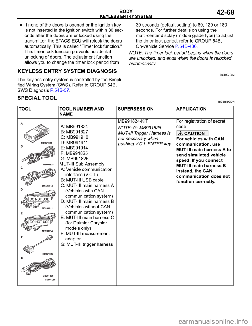
SPECIAL TOOLBGBBBGDH
TOOL TOOL NUMBER AND
NAMESUPERSESSION APPLICATION
A: MB991824
B: MB991827
C: MB991910
D: MB991911
E: MB991914
F: MB991825
G: MB991826
MUT-III Sub Assembly
A: Vehicle communication
interface (V.C.I.)
B: MUT-III USB cable
C: MUT-III main harness A
(Vehicles with CAN
communication system)
D: MUT-III main harness B
(Vehicles without CAN
communication system)
E: MUT-III main harness C
(for Daimler Chrysler
models only)
F: MUT-III measurement
adapter
G: MUT-III trigger harnessMB991824-KIT
NOTE: G: MB991826
MUT-III Trigger Harness is
not necessary when
pushing V.C.I. ENTER key.For registration of secret
code
For vehicles with CAN
communication, use
MUT-III main harness A to
send simulated vehicle
speed. If you connect
MUT-III main harness B
instead, the CAN
communication does not
function correctly.
Page 1141 of 1500
KEYLESS ENTRY SYSTEM
BODY42-74
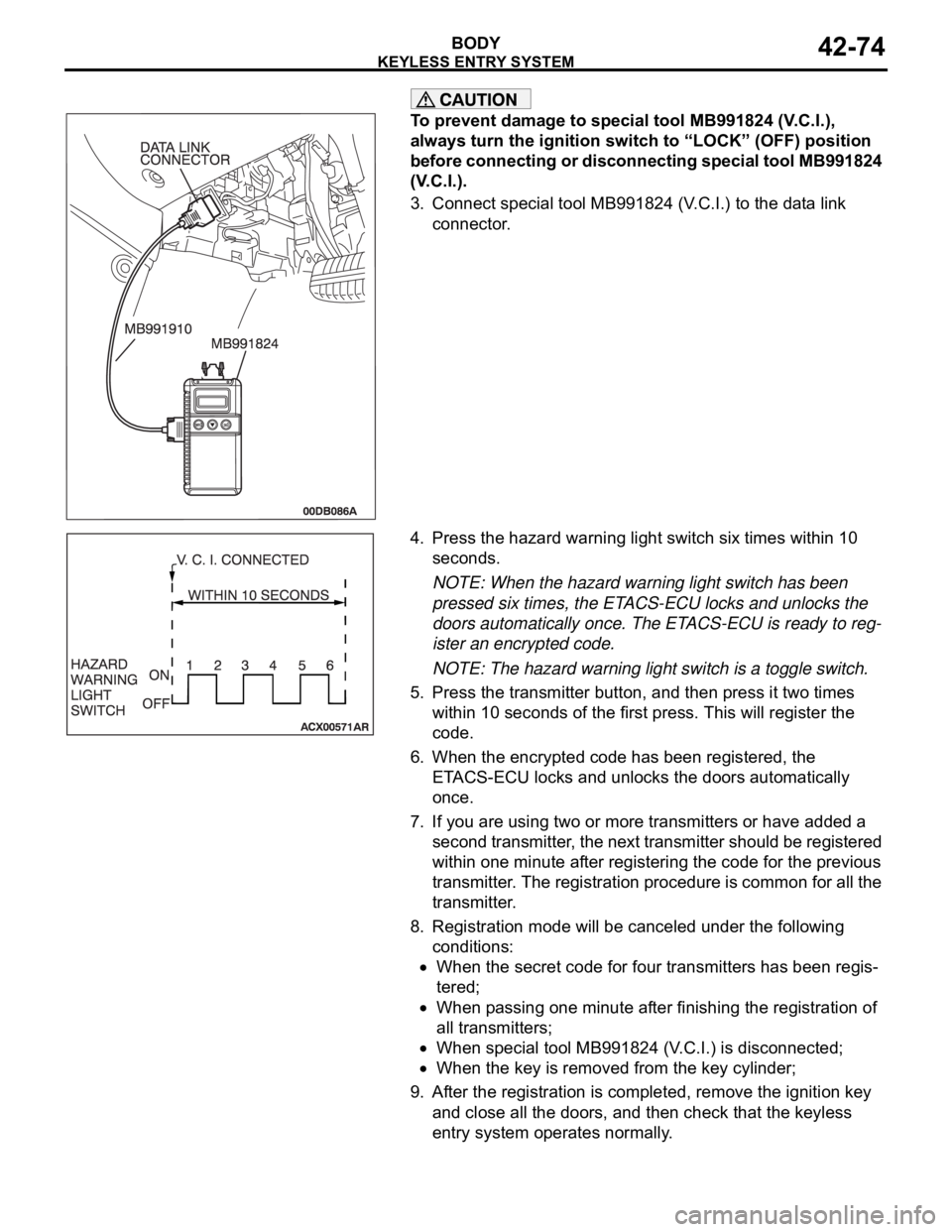
To prevent damage to special tool MB991824 (V.C.I.),
always turn the ignition switch to “LOCK” (OFF) position
before connecting or disconnecting special tool MB991824
(V.C.I.).
3. Connect special tool MB991824 (V.C.I.) to the data link
connector.
4. Press the hazard warning light switch six times within 10
seconds.
NOTE: When the hazard warning light switch has been
pressed six times, the ETACS-ECU locks and unlocks the
doors automatically once. The ETACS-ECU is ready to reg-
ister an encrypted code.
NOTE: The hazard warning light switch is a toggle switch.
5. Press the transmitter button, and then press it two times
within 10 seconds of the first press. This will register the
code.
6. When the encrypted code has been registered, the
ETACS-ECU locks and unlocks the doors automatically
once.
7. If you are using two or more transmitters or have added a
second transmitter, the next transmitter should be registered
within one minute after registering the code for the previous
transmitter. The registration procedure is common for all the
transmitter.
8. Registration mode will be canceled under the following
conditions:
When the secret code for four transmitters has been regis-
tered;
When passing one minute after finishing the registration of
all transmitters;
When special tool MB991824 (V.C.I.) is disconnected;
When the key is removed from the key cylinder;
9. After the registration is completed, remove the ignition key
and close all the doors, and then check that the keyless
entry system operates normally.
Page 1144 of 1500
SUNROOF ASSEMBLY
BODY42-77
SUNROOF INITIALIZATIONM1426004600123
The sunroof should be initialized when any of the following
components are replaced, the sunroof position is miss timed.
Roof lid glass assembly
Sunroof motor assembly.
1. Ensure the components are correctly assembled. Ensure all
the connectors are connected securely.
2. If the sunroof is already in learn mode, go to step 3. If the
sunroof is not in learn mode, enter learn mode by (1) or (2)
below.
(1) Disconnect the sunroof motor assembly connector while
the sunroof is operating.
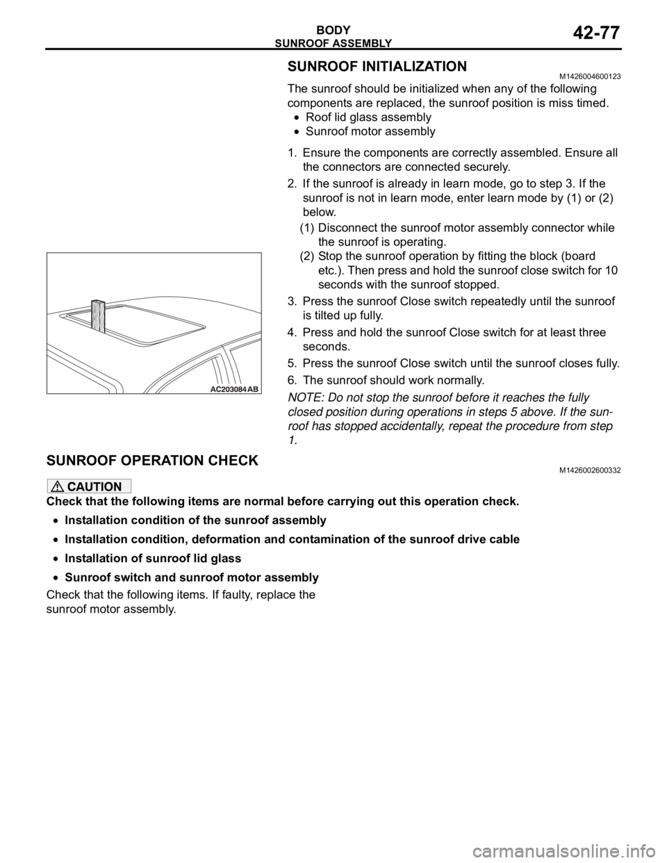
(2) Stop the sunroof operation by fitting the block (board
etc.). Then press and hold the sunroof close switch for 10
seconds with the sunroof stopped.
3. Press the sunroof Close switch repeatedly until the sunroof
is tilted up fully.
4. Press and hold the sunroof Close switch for at least three
seconds.
5. Press the sunroof Close switch until the sunroof closes fully.
6. The sunroof should work normally.
NOTE: Do not stop the sunroof before it reaches the fully
closed position during operations in steps 5 above. If the sun-
roof has stopped accidentally, repeat the procedure from step
1.
SUNROOF OPERATION CHECKM1426002600332
Check that the following items are normal before carrying out this operation check.
Installation condition of the sunroof assembly
Installation condition, deformation and contamination of the sunroof drive cable
Installation of sunroof lid glass
Sunroof switch and sunroof motor assembly
Check that the following items. If faulty, replace the
sunroof motor assembly.
Page 1222 of 1500
00-1
GROUP 00
GENERAL
CONTENTS
HOW TO USE THIS MANUAL . . . . . .00-3
TROUBLESHOOTING GUIDELINES00-6
HOW TO USE TROUBLESHOOTING /
INSPECTION SERVICE POINTS. . . .00-7
TROUBLESHOOTING CONTENTS . . . . . . 00-7
HOW TO USE THE INSPECTION
PROCEDURES . . . . . . . . . . . . . . . . . . . . . . 00-9
CONNECTOR MEASUREMENT SERVICE
POINTS . . . . . . . . . . . . . . . . . . . . . . . . . . . . 00-11
CONNECTOR INSPECTION SERVICE
POINTS . . . . . . . . . . . . . . . . . . . . . . . . . . . . 00-13
HOW TO COPE WITH INTERMITTENT
MALFUNCTIONS . . . . . . . . . . . . . . . . . . . . 00-14
INSPECTION SERVICE POINTS
FOR A BLOWN FUSE . . . . . . . . . . . . . . . . 00-16
HOW TO TREAT CURRENT TROUBLE . . 00-16
HOW TO TREAT PAST TROUBLE . . . . . . 00-16
AFFILIATED DTC REFERENCE
TABLE . . . . . . . . . . . . . . . . . . . . . . . .00-17
VEHICLE IDENTIFICATION . . . . . . .00-18
VEHICLE IDENTIFICATION NUMBER . . . 00-18
VEHICLE INFORMATION NUMBER LIST 00-19
VEHICLE COMPLIANCE PLATE . . . . . . . . 00-19
VEHICLE DATA PLATE . . . . . . . . . . . . . . . 00-20
AUSTRALIAN DESIGN RULES . . . . . . . . . 00-20OPTION CODES . . . . . . . . . . . . . . . . . . . . . 00-21
EXPORT CODES . . . . . . . . . . . . . . . . . . . . 00-21
TYRE AND LOADING PLACARD . . . . . . . . 00-21
ENGINE MODEL STAMPING . . . . . . . . . . . 00-22
PRECAUTIONS BEFORE SERVICE .00-22
SUPPLEMENTAL RESTRAINT
SYSTEM (SRS . . . . . . . . . . . . . . . . . . . . . . 00-22
HOW TO PERFORM VEHICLE
IDENTIFICATION NUMBER (VIN) WRITING00-23
SERVICING ELECTRICAL SYSTEM . . . . . 00-24
VEHICLE WASHING . . . . . . . . . . . . . . . . . . 00-24
APPLICATION OF ANTI-CORROSION
AGENTS AND UNDERCOATS . . . . . . . . . . 00-25
DIAGNOSTIC TOOL (MUT-III) . . . . . . . . . . 00-25
TOWING AND HOISTING. . . . . . . . . .00-26
GENERAL DATA AND
SPECIFICATIONS . . . . . . . . . . . . . . .00-31
TIGHTENING TORQUE . . . . . . . . . . .00-32
LUBRICATION AND MAINTENANCE 00-34
RECOMMENDED LUBRICANTS AND
LUBRICANT CAPACITIES TABLE . .00-35
Continued on next page
Page 1243 of 1500
PRECAUTIONS BEFORE SERVICE
GENERAL00-22
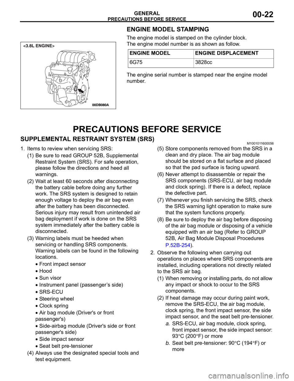
ENGINE MODEL STAMPING
The engine model is stamped on the cylinder block.
The engine model number is as shown as follow.
The engine serial number is stamped near the engine model
number.
PRECAUTIONS BEFORE SERVICE
SUPPLEMENTAL RESTRAINT SYSTEM (SRS)M1001011600056
1. Items to review when servicing SRS:
(1) Be sure to read GROUP 52B, Supplemental
Restraint System (SRS). For safe operation,
please follow the directions and heed all
warnings.
(2) Wait at least 60 seconds after disconnecting
the battery cable before doing any further
work. The SRS system is designed to retain
enough voltage to deploy the air bag even
after the battery has been disconnected.
Serious injury may result from unintended air
bag deployment if work is done on the SRS
system immediately after the battery cable is
disconnected.
(3) Warning labels must be heeded when
servicing or handling SRS components.
Warning labels can be found in the following
locations.
Front impact sensor
Hood
Sun visor
Instrument panel (passenger ’s side)
SRS-ECU
Steering wheel
Clock spring
Air bag module (Driver's or front
passenger's)
Side-airbag module (Driver's side or front
passenger's side)
Side impact sensor
Seat belt pre-tensioner
(4) Always use the designated special tools and
test equipment.(5) Store components removed from the SRS in a
clean and dry place. The air bag module
should be stored on a flat surface and placed
so that the pad surface is facing upward.
(6) Never attempt to disassemble or repair the
SRS components (SRS-ECU, air bag module
and clock spring). If there is a defect, replace
the defective part.
(7) Whenever you finish servicing the SRS, check
the SRS warning light operation to make sure
that the system functions properly.
(8) Be sure to deploy the air bag before disposing
of the air bag module or disposing of a vehicle
equipped with an air bag (Refer to GROUP
52B, Air Bag Module Disposal Procedures
P.52B-254).
2. Observe the following when carrying out
operations on places where SRS components are
installed, including operations not directly related
to the SRS air bag.
(1) When removing or installing parts, do not allow
any impact or shock to occur to the SRS
components.
(2) If heat damage may occur during paint work,
remove the SRS-ECU, the air bag module,
clock spring, the front impact sensor, the side
impact sensor, and the seat belt pre-tensioner.
a.SRS-ECU, air bag module, clock spring,
front impact sensor, the side impact sensor:
93
C (200F) or more
b.Seat belt pre-tensioner: 90
C (194F) or
more ENGINE MODEL ENGINE DISPLACEMENT
6G75 3828cc
Page 1255 of 1500
LUBRICATION AND MAINTENANCE
GENERAL00-34
LUBRICATION AND MAINTENANCEM1001001200336
Maintenance and lubrication service recommenda-
tions have been compiled to provide maximum pro-
tection for the vehicle owner's investment against all
reasonable types of driving conditions. Since these
conditions vary with the individual vehicle owner's
driving habits, the area in which the vehicle is oper-
ated and the type of driving to which the vehicle is
subjected, it is necessary to prescribe lubrication and
maintenance service on a time frequency as well as
mileage interval basis.
Oils, lubricants and greases are classified and
graded according to standards recommended by the
Society of Automotive Engineers (SAE) and the Aus-
tralian Petroleum Institute (API).
MAINTENANCE SCHEDULES
For Information on service maintenance refer to the
"Service handbook".
ENGINE OIL
Tests have shown that laboratory animals
develop skin cancer after prolonged contact with
used engine oil. Accordingly, the potential exists
for humans to develop a number of skin disor-
ders, including cancer, from such exposure to
used engine oil. Therefore, when changing
engine oil, be careful not to touch it as much as
possible. Protective clothing and gloves, that
cannot be penetrated by oil, should be worn. The
skin should be thoroughly washed with soap and
water, or use waterless hand cleaner, to remove
any used engine oil. Do not use petrol, thinners,
or solvents.Either of the following engine oils should be used:
1. Engine oil conforming to the ACEA classification:
"For service A1, A2 or A3.
2. Engine oil conforming to the API classification:
"For service SG" or higher.
FUEL USAGE STATEMENT
Using leaded petrol in this car will damage the
catalytic converters and heated oxygen sensors,
and affect the warranty coverage validity.
This vehicle must use unleaded petrol only.
This vehicle has a fuel filler tube which is especially
designed to accept only the smaller-diameter
unleaded petrol dispensing nozzle.
The 3.8L model is designed to operate on unleaded
petrol having an octane rating (DIN 51607) of 90
RON or higher.
.
PETROL CONTAINING ALCOHOL
Some petrol sold at service stations contain alcohol
although they may not be so identified.
Using fuels containing alcohol is not recommended
unless the nature of the blend can be determined as
being satisfactory, as follows.
Gasohol: A mixture of 10% ethanol and 90%
unleaded gasoline may be used in your vehicle. If
driveability problems are experienced as a result of
using gasohol, it is recommended that the vehicle be
operated on petrol.
Methanol: Do not use petrol containing methanol
(wood alcohol). Using this type of alcohol can result
in vehicle performance deterioration and damage
critical parts in the fuel system components. Fuel
system damage and performance problems resulting
from the use of petrol containing methanol may not
be covered by the new vehicle warranty.
MATERIALS ADDED TO FUEL
Indiscriminate use of fuel system cleaning agents
should be avoided. Many materials intended for gum
and varnish removal may contain highly active sol-
vents or similar ingredients that can be harmful to
gasket and diaphragm materials used in fuel system
component parts.