MITSUBISHI ECLIPSE 1991 Service Manual
Manufacturer: MITSUBISHI, Model Year: 1991, Model line: ECLIPSE, Model: MITSUBISHI ECLIPSE 1991Pages: 1216, PDF Size: 67.42 MB
Page 1101 of 1216
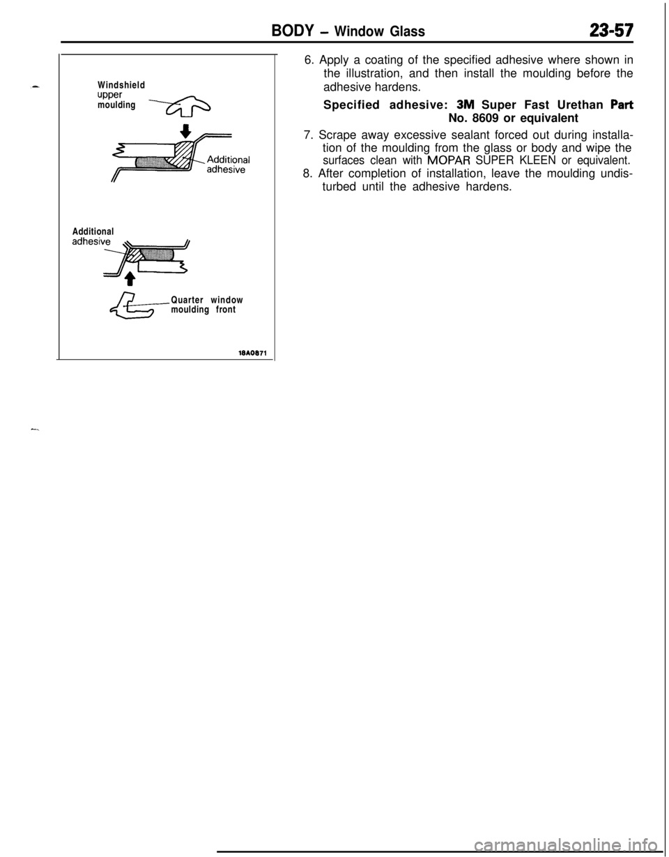
BODY - Window Glass23-57Windshield
uppermoulding
Additional
Quarter window
moulding front6. Apply a coating of the specified adhesive where shown in
the illustration, and then install the moulding before the
adhesive hardens.
Specified adhesive: 3M Super Fast Urethan PartNo. 8609 or equivalent
7. Scrape away excessive sealant forced out during installa-
tion of the moulding from the glass or body and wipe the
surfaces clean with MOPAR SUPER KLEEN or equivalent.8. After completion of installation, leave the moulding undis-
turbed until the adhesive hardens.
-.
Page 1102 of 1216
23-58BODY - Windshield
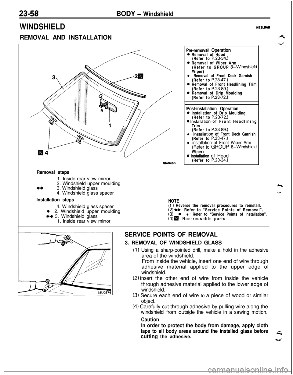
WINDSHIELD
REMOVAL AND INSTALLATION
ISA0466
Pre-removal Operation0 Removal of Hood
(Refer to P.23-34.)0 Removal of Wiper Arm
(Refer to GROUP &WindshieldWiper)
l Removal of Front Deck Garnish
(Refer to
P.23-47.)0 Removal of Front Headlining Trim
(Refer to P.23-89.)0 Removal of Drip Moulding
(Refer to P.23-72.)
Post-installation Operation0 Installation of Drip Moulding
(Refer to P.23-72.)0 Installation of Front Headlining
Trim
(Refer to
P.23-89.)l Installation of Front Deck Garnish
(Refer to
P.23-47.)l installation of Front Wiper Arm(Refer to GROUP 8-WindshieldWiper)
0 Installation of Hood
(Refer to P.23-34.)
NZBLBAR
,
Removal steps1. Inside rear view mirror
2. Windshield upper moulding
a*3. Windshield glass
4. Windshield glass spacer
Installation steps4. Windshield glass spacer
l 2. Windshield upper moulding
+a 3. Windshield glass
1. Inside rear view mirror
NOTE(1 I Reverse the removal procedures to reinstall.(2) +* : Refer to “Service Points of Removal”.(3) l + : Refer to “Service Points of Installation”.(4) H : Non-reusable parts
SERVICE POINTS OF REMOVAL3. REMOVAL OF WINDSHIELD GLASS
(1) Using a sharp-pointed drill, make a hold in the adhesivearea of the windshield.
From inside the vehicle, insert one end of wire through
adhesive material applied to the upper edge of
windshield.
(2) Insert the other end of wire from inside the vehicle
through adhesive material applied to the lower edge of
windshield.
(3) Secure each end of wire to a piece of wood or similar
object.
(4) Carefully cut through adhesive by pulling wire along the
windshield from outsi,de the vehicle in a sawing motion.
Caution
In order to protect the body from damage, apply cloth
tape to all body areas around the installed glass beforecutting the adhesive.
Page 1103 of 1216
BODY - Windshield
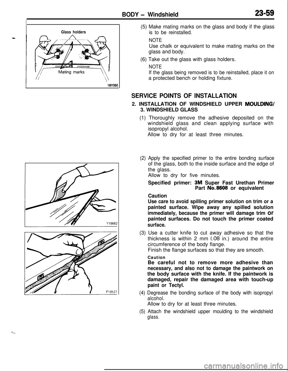
Glass holders
,(5) Make mating marks on the glass and body if the glass
is to be reinstalled.
NOTEUse chalk or equivalent to make mating marks on the
glass and body.
(6) Take out the glass with glass holders.
NOTE
If the glass being removed is to be reinstalled, place it ona protected bench or holding fixture.
SERVICE POINTS OF INSTALLATION2. INSTALLATION OF WINDSHIELD UPPER MOULDING/
3. WINDSHIELD GLASS
(1) Thoroughly remove the adhesive deposited on the
windshield glass and clean applying surface with
isopropyl alcohol.
Allow to dry for at least three minutes.
(2) Apply the specified primer to the entire bonding surfaceof the glass, both to the inside surface and the edge of
the glass.
Allow to dry for five minutes.
Specified primer:
3M Super Fast Urethan Primer
CautionPart No.8608 or equivalent
Use care to avoid spilling primer solution on trim or apainted surface. Wipe away any spilled solution
immediately, because the primer will damage trim orpainted surfaces. Do not touch the primer coated
surface.(3) Use a cutter knife to cut away adhesive so that the
thickness is within 2 mm
(.08 in.) around the entire
circumference of the body flange.
Finish the flange surfaces so that they are smooth.
Caution
Be careful not to remove more adhesive than
necessary, and also not to damage the paintwork onthe body surface with the knife. If the paintwork is
damaged, repair the damaged area with touch-up
paint or Tectyl.
(4) Degrease the bonding surface of the body with isopropyl
alcohol.Allow to dry for at least three minutes.
(5) Attach the windshield upper moulding to the windshield
glass.
Page 1104 of 1216
23-60BODY - Windshield
SECT. B-B
SECT. A-A(Other areas not illustrated are
the same as those in cross aec-tion A-A.)
Approx.ISA0520 iSAo522&jSECT. C-C(Other areas not illustrated are the same
as those in cross section A-A.1
Nozzle tip
G QApprox 7
I 28)
Approx12
t.47
1.3~0523 mm (in.) 181988
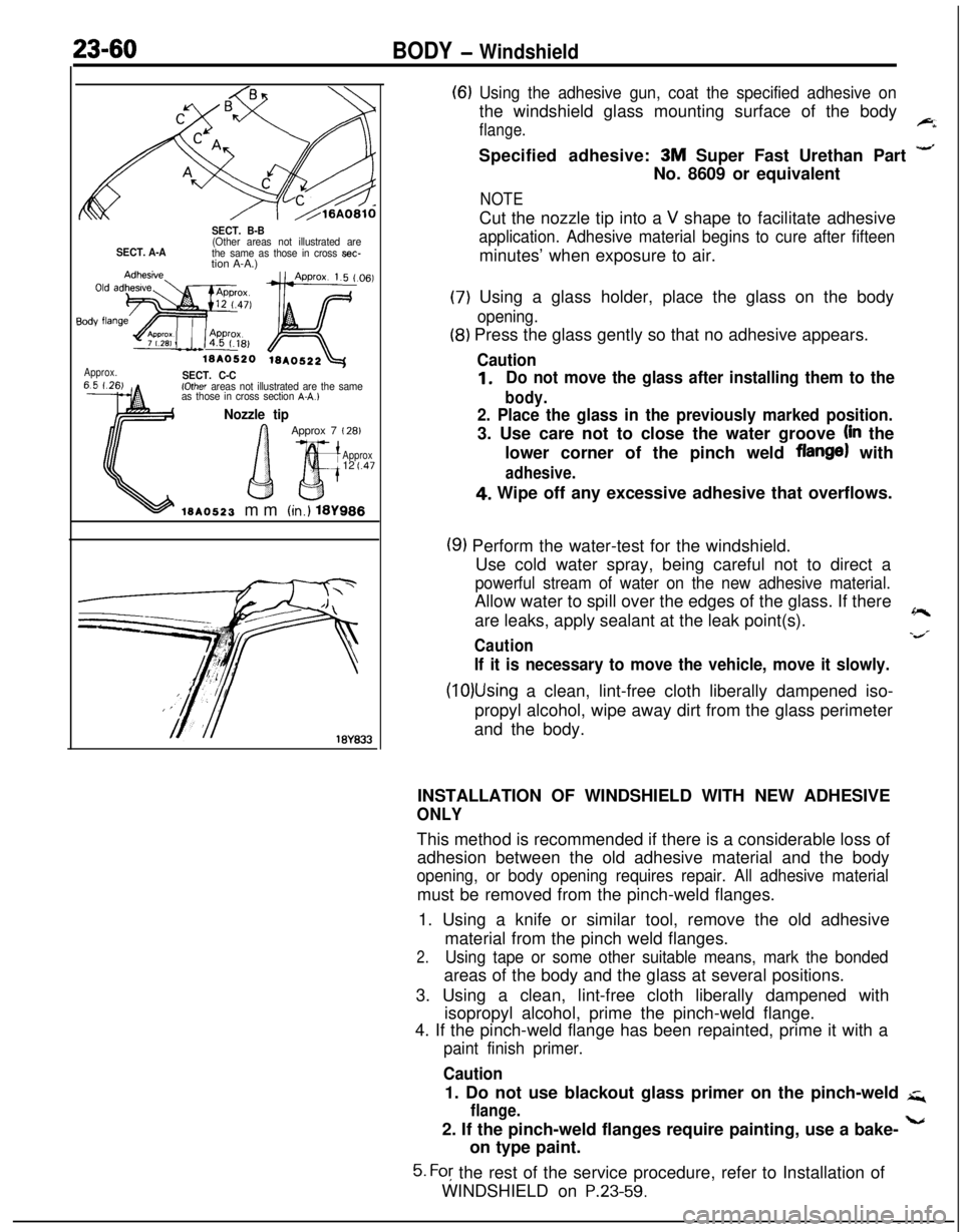
(6) Using the adhesive gun, coat the specified adhesive onthe windshield glass mounting surface of the body
flange.FiSpecified adhesive:
3M Super Fast Urethan Part -No. 8609 or equivalent
NOTECut the nozzle tip into a
V shape to facilitate adhesive
application. Adhesive material begins to cure after fifteenminutes’ when exposure to air.
(7) Using a glass holder, place the glass on the body
opening.
(8) Press the glass gently so that no adhesive appears.
Caution
1.Do not move the glass after installing them to the
body.
2. Place the glass in the previously marked position.3. Use care not to close the water groove
(in the
lower corner of the pinch weld
flange) with
adhesive.4. Wipe off any excessive adhesive that overflows.
(9) Perform the water-test for the windshield.
Use cold water spray, being careful not to direct a
powerful stream of water on the new adhesive material.Allow water to spill over the edges of the glass. If there
are leaks, apply sealant at the leak point(s).
~
Cautions/
If it is necessary to move the vehicle, move it slowly.
(10)Using a clean, lint-free cloth liberally dampened iso-
propyl alcohol, wipe away dirt from the glass perimeter
and the body.
INSTALLATION OF WINDSHIELD WITH NEW ADHESIVE
ONLYThis method is recommended if there is a considerable loss of
adhesion between the old adhesive material and the body
opening, or body opening requires repair. All adhesive materialmust be removed from the pinch-weld flanges.
1. Using a knife or similar tool, remove the old adhesive
material from the pinch weld flanges.
2.Using tape or some other suitable means, mark the bondedareas of the body and the glass at several positions.
3. Using a clean, lint-free cloth liberally dampened with
isopropyl alcohol, prime the pinch-weld flange.
4. If the pinch-weld flange has been repainted, prime it with a
paint finish primer.
Caution1. Do not use blackout glass primer on the pinch-weld
q
flange.2. If the pinch-weld flanges require painting, use a bake-
Lon type paint.
5. For the rest of the service procedure, refer to Installation of
WINDSHIELD on
P.23-59.
Page 1105 of 1216
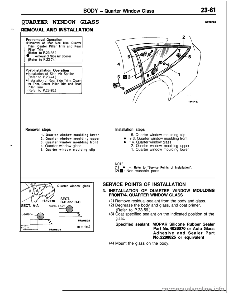
BODY - Quarter Window Glass23-61QUARTER WINDOW GLASS
N22LEAKPre-removal Operation
@Removal of Rear Side Trim, Quarter
Trim. Center Pillar Trim and Rear
IPillar’ Trim
I(Refer to
P.23-85.)l kemoval of Side Air SpoilerI(Refer to
P.23-74.)Iter Trim, Center Pillar Trim and Rear
Removal steps1. Quarter window moulding lower
2. Quarter window moulding upper
3. Quarter window moulding front
4. Quarter window glass
5. Quarter window moulding clipInstallation steps5. Quarter window moulding clip
l + 3. Quarter window moulding front
l * 4. Quarter window glass
2. Quarter window moulding upper1. Quarter window moulding lower
NOTE(1) l + : Refer to “Service Points of Installation”.(2) $ : Non-reusable parts
Quarter window glass
SECT.B-B and C-C
SECT. A-A
18AO521mm
(in.)18AO521
-ISERVICE POINTS OF INSTALLATION3. INSTALLATION OF QUARTER WINDOW
MOULDING
FRONT/4. QUARTER WINDOW GLASS
(1) Remove residual-sealant from the body and glass.
(2) Degrease the body and glass, and coat primer.
(Refer to
P.23-59.)
(3) Coat specified sealant on the indicated position of the
glass.Specified sealant: MOPAR Silicone Rubber Sealer
Part No.4626070 or Auto Glass
Adhesive and Sealer PartNo.2298825 or equivalent
(4) Mount the glass on the body.
Page 1106 of 1216
23-62BODY - Liftgate Window Glass
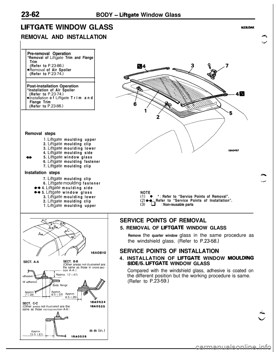
LIFTGATE WINDOW GLASSN22LDAK
REMOVAL AND INSTALLATION
Pre-removal Operation*Removal of Liftgate Trim and Flange
Trim
(Refer to
P.23-86.)aRemoval of Air Spoiler
(Refer to P.23-74.)Post-installation Operation
*Installation of Air Spoiler
(Refer to
P.23-74.)*Installation of Liftgate Trim and
Flange Trim
(Refer to
P.23-86.)
I
Removal steps
I. Liftgate moulding upper
2. Liftgate moulding clip
3. Liftgate moulding lower
4. Liftgate moulding side
o*5. Liftgate window glass
6. Liftgate moulding fastener
7.
Liftgate moulding clip
Installation steps7.
Liftgate moulding clip
6.
Liftgate moulding fastener
M 4. Liftgate moulding side
w 5. Liftgate window glass
3.
Liftgate moulding lower
2. Liftgate moulding clip1. Liftgate moulding upper
WA0487NOTE
(1) l * : Refer to “Service Points of Removal”.(2) .+ : Refer to “Service Points of Installation”.(3) q : Non-reusable parts
SECT. A-A
SECT. B-B(Other areas not illustrated arethe same as those in cmss sec-
SECT. C-C(Other areas not illustrated are thesame as those ,ncrms sectmn A-A )1ar40525mm
(in.)
ISA0526
SERVICE POINTS OF REMOVAL5. REMOVAL OF
LIFTGATE WINDOW GLASS
Remove the quarter window glass in the same procedure as
the windshield glass. (Refer to
P.23-58.)
SERVICE POINTS OF INSTALLATION4. INSTALLATION OF
LIFTGATE WINDOW MOULDINGSIDE/5.
LIFTGATE WINDOW GLASS
Compared with the windshield glass, adhesive is coated onthe different position but the working procedure is same.
(Refer to
P.23-59.)
Page 1107 of 1216
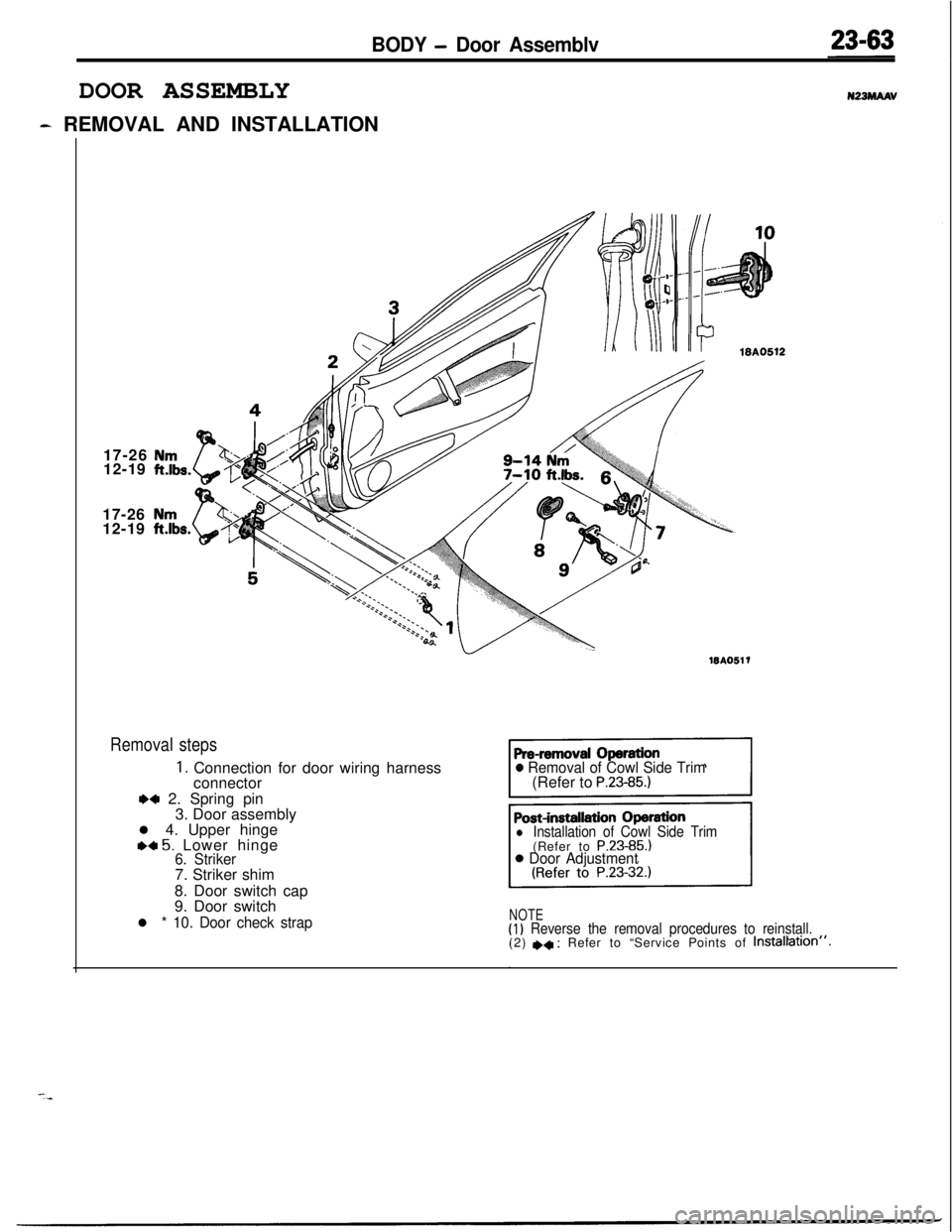
BODY - Door AssemblvDOOR ASSEMBLY
- REMOVAL AND INSTALLATION
N22MAW17-26
12-19
17-26
12-19
15A0511
Removal steps
1. Connection for door wiring harness
connector
*+ 2. Spring pin
3. Door assembly
l 4. Upper hinge
.c 5. Lower hinge6. Striker7. Striker shim
8. Door switch cap
9. Door switch
l * 10. Door check strap
0 Removal of Cowl Side Trim(Refer to P.23-85.)
l Installation of Cowl Side Trim(Refer to P.23-85.)
0 Door Adjustment
NOTE(I) Reverse the removal procedures to reinstall.(2) I)+ : Refer to “Service Points of Instal$tion”.
Page 1108 of 1216
23-64BODY - Door AssemblyON-OFF
stroke
1*,,.$18A0158
Type BON-OFF
stroke
“1 /- 16PO192klBA0459
Identification mark
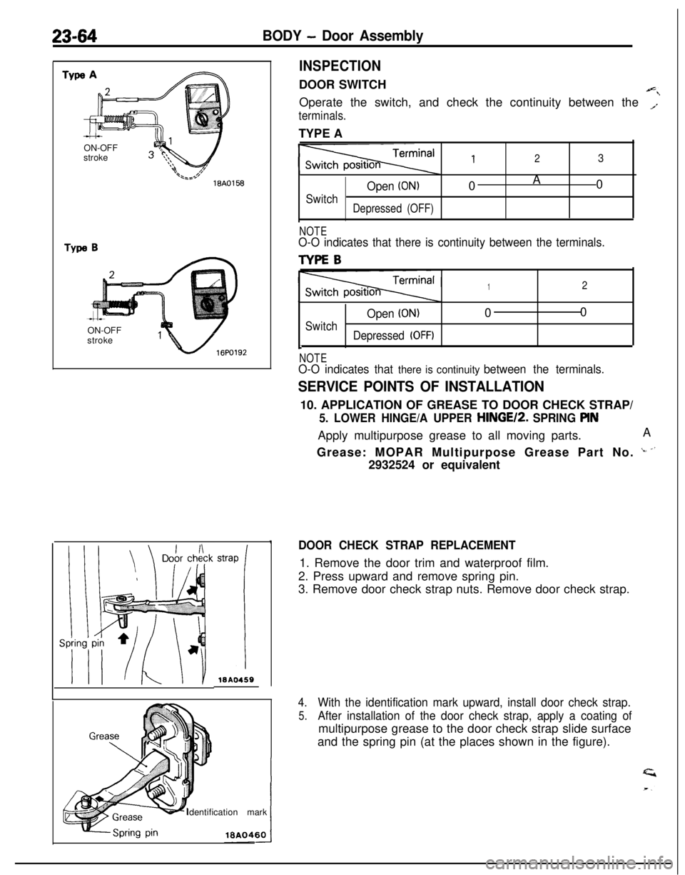
INSPECTIONDOOR SWITCH
Operate the switch, and check the continuity between the
T
terminals.TYPE A
123
Open (ON)0A
0
SwitchDepressed (OFF)
NOTEO-O indicates that there is continuity between the terminals.
TYPEB
12
Open (ON)00
Switch
Depressed (OFF)b
NOTEO-O indicates that there is continuity between the terminals.
SERVICE POINTS OF INSTALLATION10. APPLICATION OF GREASE TO DOOR CHECK STRAP/
5. LOWER HINGE/A UPPER HINGE12. SPRING PINApply multipurpose grease to all moving parts.A
Grease: MOPAR Multipurpose Grease Part No.
‘- -’2932524 or equivalent
DOOR CHECK STRAP REPLACEMENT1. Remove the door trim and waterproof film.
2. Press upward and remove spring pin.
3. Remove door check strap nuts. Remove door check strap.
4.With the identification mark upward, install door check strap.
5.After installation of the door check strap, apply a coating ofmultipurpose grease to the door check strap slide surface
and the spring pin (at the places shown in the figure).
Page 1109 of 1216
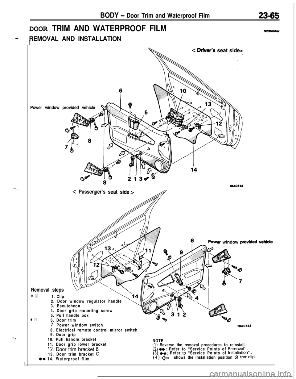
BODY - Door Trim and Waterproof Film2345
DOOR TRIM AND WATERPROOF FILM
REMOVAL AND INSTALLATIONI
Power window provided vehicle%l \PL
< Oriver’s seat side>
2i36~4
15AO514<
Passenaer’s
seat
side >
er window provkkd
Removal steps2. Door window regulator handle
3. Escutcheon
4. Door grip mounting screw
5. Pull handle box
l *6. Door trim
l +1. Clip
7. Power window switchWA05138. Electrical remote control mirror switch
9. Door grip
10. Pull handle bracket
11. Door grip lower bracketNOTE
(1) Reverse the removal procedures to reinstall.12. Door trim bracket B(2) a* : Refer to “Service Points of Removal”.13. Door trim bracket
C(3) +* : Refer to “Service Points of Installa~lon”,
*c 14. Waterproof film(4) +shows the installation position of trim Clip.
I
Page 1110 of 1216
23-66BODY - Door Trim and Waterproof Film/Door Glass and Regulator
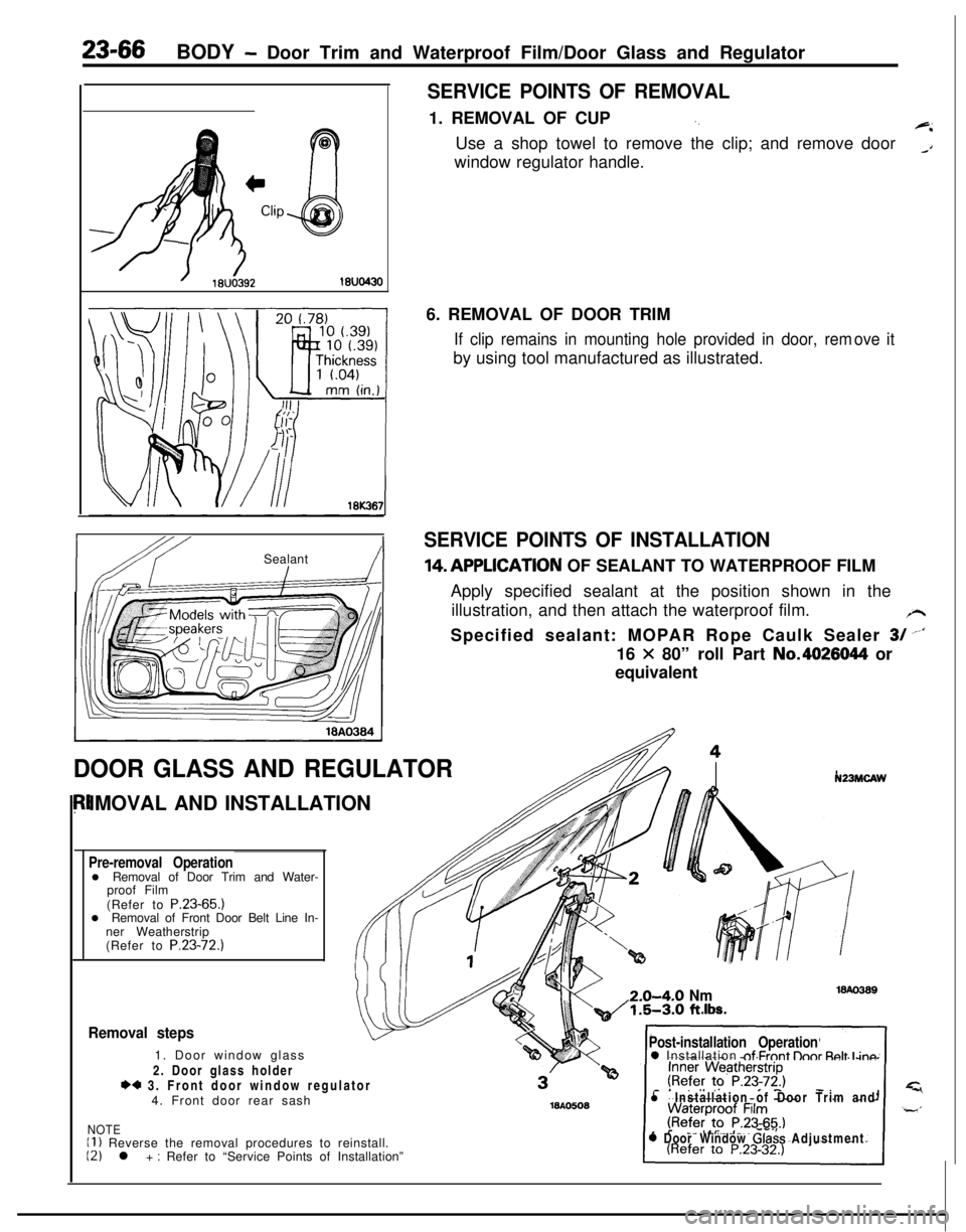
SERVICE POINTS OF REMOVAL1. REMOVAL OF CUP
‘.+iUse a shop towel to remove the clip; and remove door
_Awindow regulator handle.
IbY ISealant!I6. REMOVAL OF DOOR TRIM
If clip remains in mounting hole provided in door, remby using tool manufactured as illustrated.ove it
SERVICE POINTS OF INSTALLATION14,APPLlCATlON OF SEALANT TO WATERPROOF FILM
Apply specified sealant at the position shown in the
illustration, and then attach the waterproof film.
/rSpecified sealant: MOPAR Rope Caulk Sealer
3/ --‘I16
X 80” roll Part No.4026044 or
equivalent
DOOR GLASS AND REGULATORIMOVAL AND INSTALLATION
Pre-removal Operationl Removal of Door Trim and Water-
proof Film
(Refer to P.23-65.)
l Removal of Front Door Belt Line In-
ner Weatherstrip
(Refer to P.23-72.)
N23MCAW2.0-4-O
Nm1.5-3.0 ft.lbs.
Removal steps1. Door window glass
2. Door glass holder
*4 3. Front door window regulator
4. Front door rear sash
NOTEII ) Reverse the removal procedures to reinstall.12) l + : Refer to “Service Points of Installation”
Post-installation Operation0 Installation nf Frnnt lhnr Rnlt I inn
l Installation of Door Trim and
0 Door Window Glass Adjustment