air filter MITSUBISHI ECLIPSE 1991 User Guide
[x] Cancel search | Manufacturer: MITSUBISHI, Model Year: 1991, Model line: ECLIPSE, Model: MITSUBISHI ECLIPSE 1991Pages: 1216, PDF Size: 67.42 MB
Page 431 of 1216
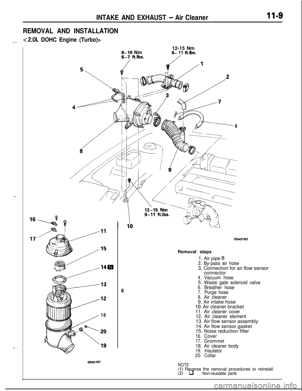
INTAKE AND EXHAUST - Air Cleaner
REMOVAL AND INSTALLATION
<2.0L DOHC Engine (Turbo)>
II-S
8-10 Nm6-7, ft.lbs.12-15 Nm9- 11 ftlbs.
/
8
18
05AO167
605A0182
Removal steps
1. Air pipe
B2. By-pass air hose3. Connection for air flow sensor
connector
4.Vacuum hose
5. Waste gate solenoid valve
6.Breather hose7.Purge hose8.Air cleaner9. Air intake hose
10. Air cleaner bracket11. Air cleaner cover
12. Air cleaner element13. Air flow sensor assembly
14. Air flow sensor gasket
15. Noise reduction filter
16.Cover17.Grommet
18. Air cleaner body
19.Insulator20.Collar
NOTE(1) Reverse the removal procedures to reinstall.(2) q : Non-reusable parts
Page 455 of 1216
14-IFUEL SYSTEM
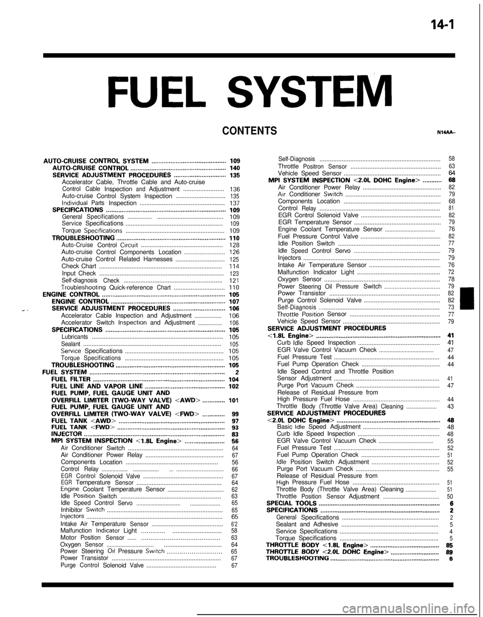
CONTENTS
AUTO-CRUISECONTROLSYSTEM...........................................109AUTO-CRUISECONTROL.......................................................140SERVICEADJUSTMENTPROCEDURES..............................135Accelerator Cable, Throttle Cable and Auto-cruise
ControlCableInspectionandAdjustment........................136Auto-cruise
ControlSystemInspection.............................135lndrvrdualPartsInspection..................................................137SPECIFICATIONS.....................................................................109GeneralSpecifications.......................................................109ServiceSpecifications
.........................................................109Torque Specrfications..........................................................109TROUBLESHOOTING...............................................................110Auto-CruiseControlCircurt................................................128Auto-cruise
ControlComponentsLocation........................126Auto-cruise Control Related Harnesses
.............................125Check Chart
........................................................................114Input Check.........................................................................123Self-diagnosis
Check..........................................................121Troubleshootrng
Quick-referenceChart..............................110ENGINECONTROL.......................................................................105ENGINECONTROL..................................................................107--SERVICEADJUSTMENTPROCEDURES..............................106Accelerator Cable Inspection and Adjustment..................106Accelerator Switch Inspectron and Adjustment................106SPECIFICATIONS.....................................................................105Lubricants.............................................................................105Sealant.................................................................................105ServiceSpecifications
..........................................................105TorqueSpecifications..........................................................105TROUBLESHOOTING...............................................................105FUELSYSTEM..............................................................................2FUELFILTER............................................................................104FUELLINEANDVAPORLINE..............................................102FUEL PUMP, FUEL GAUGE UNIT ANDOVERFILL LIMITER(TWO-WAY VALVE)
Switch........................................................64Air Conditioner Power Relay
..............................................67Components
Location......................................................56
ControlRelay
.................................................................66EGRControlSolenoidValve...............................................67EGRTemperatureSensor..................................................64Engine Coolant Temperature Sensor
.................................62IdlePosrtionSwitch
...........................................................63IdleSpeedControlServo
.............................
....................65InhibitorSwitch....................................................................65hjeCtOrS................................................................................65IntakeAirTemperatureSensor..........................................6’2MalfunctionlndtcatorLight
..........................................58MotorPosition
Sensor................................................63OxygenSensor
.................................................................64Power Steering 011 Pressure Swatch...........................65PowerTransistor
................................................................67PurgeControlSolenoidValve.........................................67
Self-Diagnosis.......................................................................
ThrottlePositronSensor.....................................................
Vehicle Speed Sensor.........................................................MPI
SYSTEMINSPECTION<2.0L DOHCEngine>...........Air Conditioner Power Relay..............................................
Arr Conditioner Swatch........................................................
Components Location
.........................................................
Control
Relay.......................................................................
EGR Control Solenoid Valve...............................................
EGR Temperature Sensor
...................................................
Engine Coolant Temperature Sensor
.................................Fuel Pressure Control Valve...............................................
Idle Position Switch
............................................................
Idle
SpeedControlServo...................................................Injectors
................................................................................
Intake Air Temperature Sensor..........................................
Malfunction Indicator Light.................................................
Oxygen Sensor
....................................................................
Power
Steering
OilPressureSwitch.................................Power Transistor
.................................................................
Purge Control Solenoid Valve.............................................
Self-Diaanosis.......................................................................
58
63
2382
79
688182
79
7682
77
79
79
76
727879
82
8273ThrottletiPosition Sensor
.....................................................77Vehicle Speed Sensor
.........................................................79SERVICE ADJUSTMENT PROCEDURES<1.8L Engine>........................................................................41Curb Idle Speed Inspection
................................................41EGR Valve Control Vacuum Check....................................47Fuel Pressure Test
..............................................................44Fuel Pump Operation Check
..............................................44Idle Speed Control and Throttle Position
Sensor Adjustment
..............................................................
41Purge Port Vacuum Check
.................................................47Release of Residual Pressure from
High Pressure Fuel Hose
...................................................
44Throttle
Body(Throttle Valve Area)Cleaning....................43SERVICE ADJUSTMENT PROCEDURES<2.0LDOHCEngine>............................................................48Basic Idle Speed Adjustment
.............................................
48
Curb Idle Speed Inspection
................................................48EGR Valve Control Vacuum Check....................................55Fuel Pressure Test
..............................................................52Fuel Pump Operation Check
..............................................51Idle Position Switch Adjustment........................................52Purge Port Vacuum Check
.................................................55Release of Residual Pressure from
High Pressure Fuel Hose
...................................................51Throttle Body (Throttle Valve Area) Cleaning....................51ThrottlePositionSensorAdjustment.................................50SPECIALTOOLS......................................................................6SPECIFICATIONS.....................................................................2GeneralSpecifications.........................................................2Sealant and Adhesive
.........................................................5Service Specifications
..........................................................4Torque Specifications
..........................................................5THROlTLEBODY<1.8LEngine>........................................85THROlTLE BODY <2.0L DOHC Engine>............................89TROUBLESHOOTING...............................................................6
Page 456 of 1216
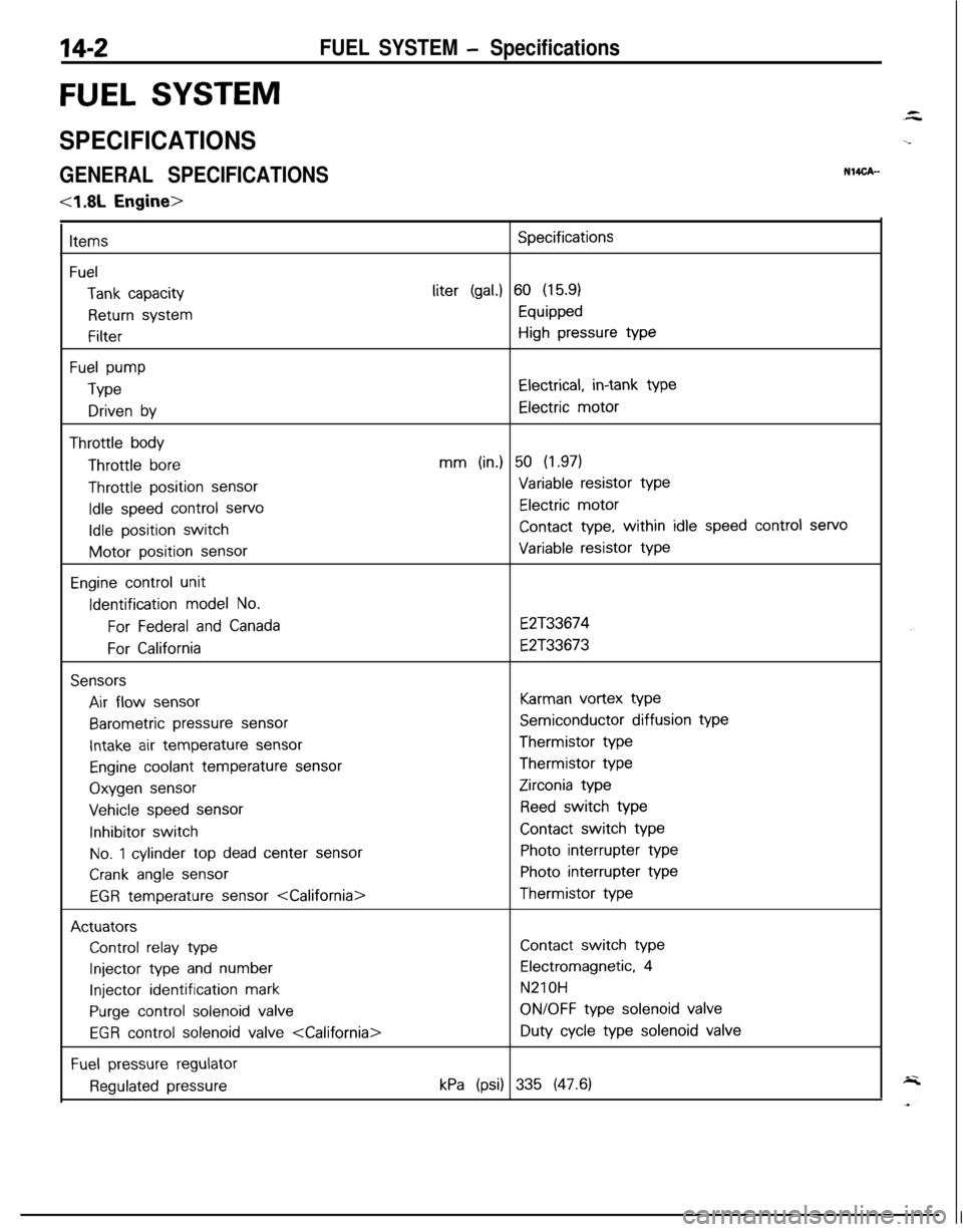
14-2FUEL SYSTEM - Specifications
FUEL SYSTEM
SPECIFICATIONS
GENERAL SPECIFICATIONSNW%-
4.8L Engine>
Items
Fuel
Tank capacity
Return system
Filter
Fuel pump
Type
Driven by
Throttle bodyThrottle
bore
Throttle position sensor
Idle speed control servo
Idle position switchMotor position
sensor
Engine control unitIdentification
model No.
For Federal and Canada
For California
SensorsAir flow
sensor
Barometric pressure sensor
Intake air temperature sensor
Engine coolant temperature sensorOxygen
sensor
Vehicle speed sensorInhibitor switch
No. 1 cylinder top dead center sensor
Crank angle sensor
EGR temperature sensor
Control relay type
Injector type and number
Injector identification mark
Purge control solenoid valve
EGR control solenoid valve
Fuel pressure regulator
Regulated pressure
Specificationsliter
(gal.) 60 (15.9)
Equipped
High pressure type
Electrical, in-tank type
Electric motor
mm (in.) 50 (1.97)
Variable resistor type
Electric motor
Contact type, within idle speed control servo
Variable resistor type
E2T33674
E2T33673
Karman vortex type
Semiconductor diffusion typeThermistor typeThermistor type
Zirconia type
Reed switch type
Contact switch type
Photo interrupter type
Photo interrupter typeThermistor type
Contact switch type
Electromagnetic, 4
N210H
ON/OFF type solenoid valveDuty
cycle type solenoid valve
kPa (psi) 335 (47.6)
Page 457 of 1216
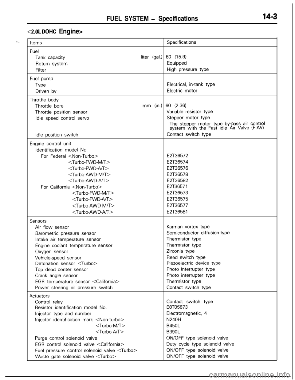
FUEL SYSTEM - Specifications14-3
<2.0L DOHC Engine>
ItemsSpecifications
Fuel
Tank capacityliter (gal.) 60 (15.9)
Return systemEquipped
FilterHigh pressure type
Fuel pump
TypeElectrical, in-tank type
Driven byElectric motor
Throttle bodyThrottle
boremm (in.) 60 (2.36)Throttle position
sensorVariable resistor type
Idle speed control servoStepper motor type
The stepper motor type by- ass air controlsystem with the Fast Idle6!rr Valve (FIAV)
Idle position switchContact switch type
Engine control unitIdentification
model No.
For Federal
E2T36574
E2T36576
E2T36578
E2T36582
For California
E2T36573
E2T36575
E2T36577
E2T36581
SensorsAir flow
sensorKarman vortex type
Barometric pressure sensorSemiconductor diffusion-type
Intake air temperature sensorThermistor type
Engine coolant temperature sensorThermistor type
Oxygen sensorZirconia type
Vehicle-speed sensorReed switch typeDetonation
sensor
Top dead center sensorPhoto interrupter type
Crank angle sensorPhoto interrupter type
EGR temperature sensor
Power steering oil pressure switchContact switch type4ctuators
Control relayContact switch type
Resistor identification model No.E8T05873
Injector type and numberElectromagnetic, 4
Injector identification mark
B450L
B390L
Purge control solenoid valveON/OFF type solenoid valve
EGR control solenoid valve
Fuel pressure control solenoid valve
gate solenoid valve
Page 500 of 1216
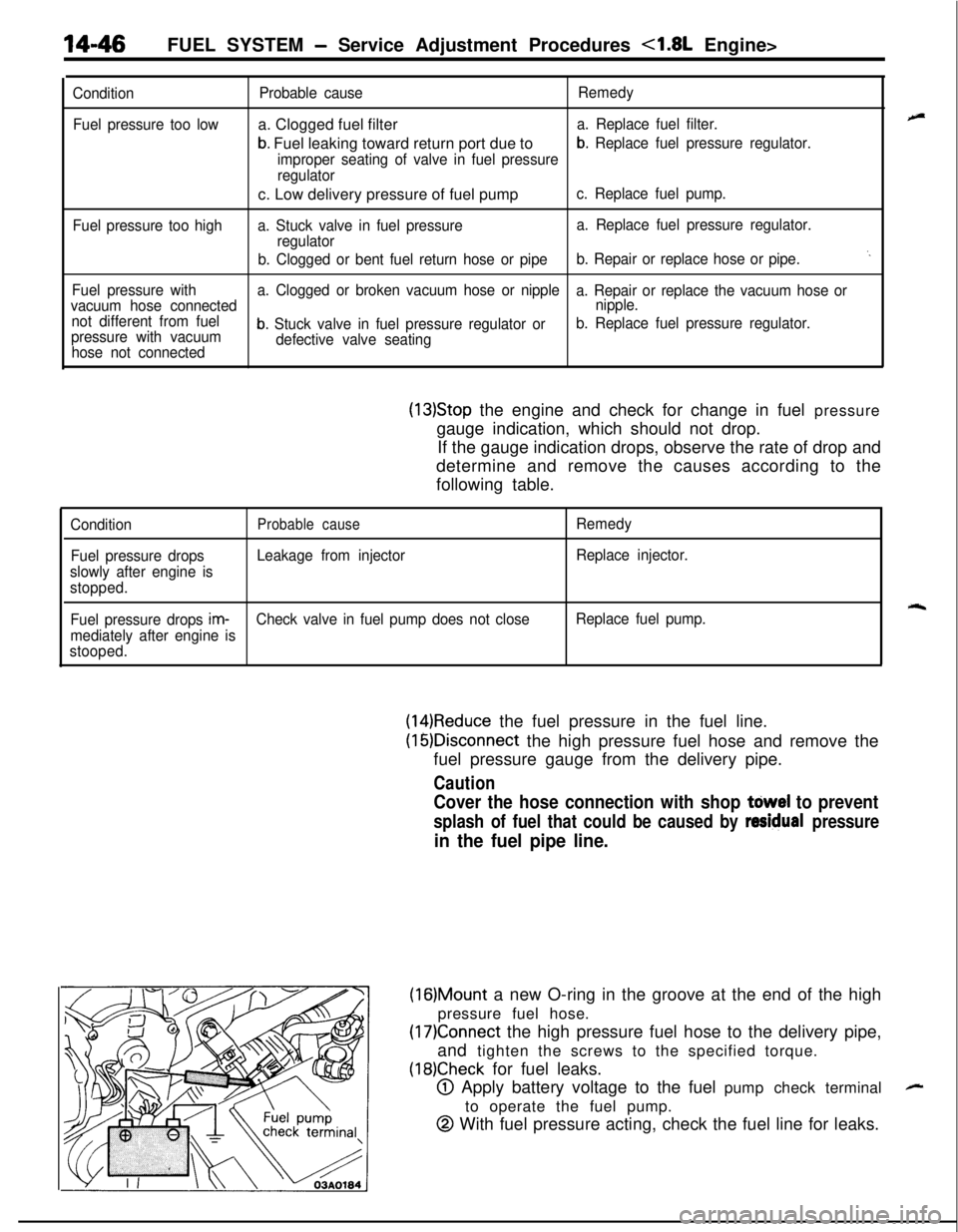
14-46FUEL SYSTEM - Service Adjustment Procedures <1.8L Engine>
Condition
Fuel pressure too low
Fuel pressure too highProbable causea. Clogged fuel filter
b. Fuel leaking toward return port due to
Remedy
a. Replace fuel filter.
improper seating of valve in fuel pressure
b. Replace fuel pressure regulator.
regulatorc. Low delivery pressure of fuel pump
c. Replace fuel pump.
a. Stuck valve in fuel pressurea. Replace fuel pressure regulator.
regulator
b. Clogged or bent fuel return hose or pipeb. Repair or replace hose or pipe.
‘.
Fuel pressure witha. Clogged or broken vacuum hose or nipple
a. Repair or replace the vacuum hose or
vacuum hose connectednipple.
not different from fuel
pressure with vacuum
b. Stuck valve in fuel pressure regulator orb. Replace fuel pressure regulator.
hose not connecteddefective valve seating
(13)Stop the engine and check for change in fuel pressure
gauge indication, which should not drop.
If the gauge indication drops, observe the rate of drop and
determine and remove the causes according to the
following table.
ConditionProbable causeRemedy
Fuel pressure dropsLeakage from injectorReplace injector.
slowly after engine is
stopped.
rqFuel pressure drops im-Check valve in fuel pump does not closeReplace fuel pump.
mediately after engine is
stooped.
(14)Reduce the fuel pressure in the fuel line.
(16)Disconnect the high pressure fuel hose and remove the
fuel pressure gauge from the delivery pipe.
Caution
Cover the hose connection with shop tdwel to prevent
splash of fuel that could be caused by residual pressure
in the fuel pipe line.
(16)Mount a new O-ring in the groove at the end of the high
pressure fuel hose.
(17)Connect the high pressure fuel hose to the delivery pipe,
and tighten the screws to the specified torque.
(18)Check for fuel leaks.
@ Apply battery voltage to the fuel pump check terminal
to operate the fuel pump.
@ With fuel pressure acting, check the fuel line for leaks.
-
Page 508 of 1216
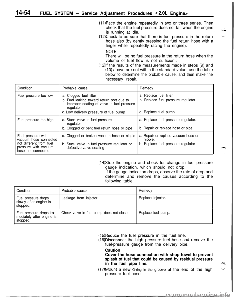
14-54FUEL SYSTEM - Service Adjustment Procedures <2.0L Engine>
(11)Race the engine repeatedly in two or three series. Then
check that the fuel pressure does not fall when the engine
is running at idle.
(12)Check to be sure that there is fuel pressure in the return
hose also (by gently pressing the fuel return hose with a
finger while repeatedly racing the engine).
NOTEThere will be no fuel pressure in the return hose when the
volume of fuel flow is not sufficient.
(13)lf the results of the measurements made in steps (9) and
(10) above are not within the standard value, use the table
below to determine the probable cause, and then make the
necessary repair.
Condition
Fuel pressure too lowProbable causeRemedy
a. Clogged fuel filtera. Replace fuel filter.
b. Fuel leaking toward return port due tob. Replace fuel pressure regulator.
improper seating of valve in fuel pressure
regulator
c. Low delivery pressure of fuel pumpc. Replace fuel pump.
Fuel pressure too higha. Stuck valve in fuel pressure
a. Replace fuel pressure regulator.regulator
b. Clogged or bent fuel return hose or pipeb. Repair or replace hose or pipe.
Fuel pressure witha. Clogged or broken vacuum hose or nipplea. Repair or replace vacuum hose or
vacuum hose connected
nipple.
not different from fuel
pressure with vacuumb. Stuck valve in fuel pressure regulator or
b. Replace fuel pressure regulator.
hose not connecteddefective valve seating
(14)Stop the engine and check for change in fuel pressure
gauge indication, which should not drop.
If the gauge indication drops, observe the rate of drop and
determine and remove the causes according to the
following table.
Condition
Fuel pressure drops
slowly after engine is
stopped.Probable cause
Leakage from injectorRemedy
Replace injector.
Fuel pressure drops
im-Check valve in fuel pump does not closeReplace fuel pump.
mediately after engine is
stopped.
(15)Reduce the fuel pressure in the fuel line.
(16)Disconnect the high pressure fuel hose and remove the
fuel-pressure gauge from the delivery pipe.
Caution
Cover the hose connection with shop towel to prevent
splash of fuel that could be caused by residual pressurein the fuel pipe line.
(17)Mount a new O-ring in the groove at the end of the high
pressure fuel hose.
Page 661 of 1216
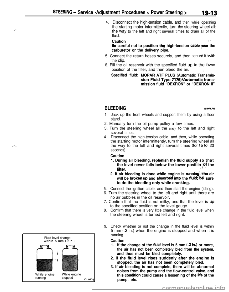
STEERING - Service -Adjustment Procedures < Power Steering >IgJf~
4.Disconnect the high-tension cable, and then while operating
the starting motor intermittently, turn the steering wheel all;
the way to the left and right several times to drain all of the
fluid.
Caution, 35
Be careful not to position thq high-tension able ye&r the
carburetor or the delivery pipe.5. Connect the return hoses securely, and then
secur& it ,with
the clip.6. Fill the oil reservoir with the specified fluid up
td the Ibwerposition of the filter, and then bleed the air.
.’
Specified fluid:MOPAR ATF PLUS (Automatic Transmis-sion Fluid Type 7176)/Automatic trans-
mission fluid “DEXRON” or “DEXRON II”Fluid level change:
within
5 mm (2 in.)While engineWhile engine
runningstoppedl?lrnl?J3
BLEEDINGNlSFKAG
1.Jack up the front wheels and support them by using a floor
stand.2. Manually turn the oil pump pulley a few times.
3. Turn the steering wheel all the way to the left and right
several times.
4.Disconnect the high-tension cable, and then, while operatingthe starting motor intermittently, turn the steering wheel all
the way to the left and right several times
(for 1-5 to 20
seconds).
Caution
1. During air bleeding, replenish the fluid supply so thatthe level never falls below the lower positiin
@f the
eiter.I .“:
2. If air bleeding is done while engine is runnind, ‘the air
will be
brokeir up and absorbed intti the fluid;‘?ti’ sureto do the bleeding only while cranking.
5.Connect the ignition cable, and then start the engine (idling).6. Turn the steering wheel to the left and right until there are
no air bubbles in the oil reservoir.
7. Confirm that the fluid is not milky, and that the level is
upito the specified position on the level gauge.
8.Confirm that there is very little change in the fluid level whenthe steering wheel is turned left and right.
9.Check whether or not the change in the fluid level is within5 mm
(.2 in.) when the engine is stopped and when it is
running.
Caution
1.If the change of the fluid level is 5 mm I.2 in.) or more,
the air has not been completely bled from the system,
and thus must be bled completely.2. If the fluid level rises suddenly after the engine is
stopped, the air has not been completely bled.
3. If air bleeding is not complete, there will be abnormal
noises from the pump and the flow-control valve, and
this
condition could cause a lessening of the life of the
pump, etc.
Page 861 of 1216
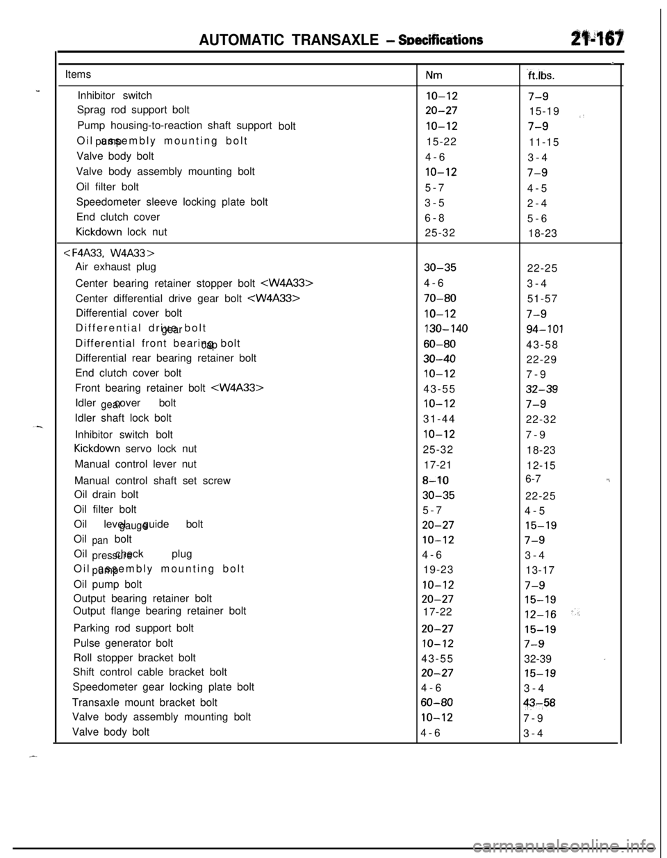
AUTOMATIC TRANSAXLE - SeecificdionsItems
Inhibitor switch
Sprag rod support bolt
Pump housing-to-reaction shaft support
bolt
Oil assembly mounting bolt
pumpValve body bolt
Valve body assembly mounting bolt
Oil filter bolt
Speedometer sleeve locking plate bolt
End clutch cover
Kickdown lock nut
< F4A33.W4A33 >Air exhaust plug
Center bearing retainer stopper bolt
Differential drive bolt
gearDifferential front bearing bolt
capDifferential rear bearing retainer bolt
End clutch cover bolt
Front bearing retainer bolt
gearIdler shaft lock bolt
Inhibitor switch bolt
Kickdown servo lock nut
Manual control lever nut
Manual control shaft set screw
Oil drain bolt
Oil filter bolt
Oil level guide bolt
gaugeOil bolt
panOil check plug
pressureOil assembly mounting bolt
pumpOil pump bolt
Output bearing retainer bolt
Output flange bearing retainer bolt
Nm
IO-12
20-27
10-1215-22
4-6
10-125-7
3-5
6-8
25-32
30-354-6
70-80
10-12
130-140
60-80
30-40
10-1243-55
10-1231-44
IO-1225-32
17-21
8-10
30-355-7
20-27
10-124-6
19-23
10-12
20-2717-22
,I
‘ft.lbs.
7-915-19
,,
7-911-15
3-4
7-94-5
2-4
5-6
18-23
22-25
3-4
51-57
7-9
94-10143-58
22-29
7-9
32-39
7-922-32
7-9
18-23
12-15
6-7
-_22-25
4-5
15-19
7-93-4
13-17
7-9
15-19
12-16"/Parking rod support bolt
20-2715-19Pulse generator bolt
IO-127-9Roll stopper bracket bolt
43-55
32-39
'Shift control cable bracket bolt
20-2715-19Speedometer gear locking plate bolt
4-6
3-4
Transaxle mount bracket bolt
60-80$-,58Valve body assembly mounting bolt
10-127-9
Valve body bolt
4-6
3-4
-.
Page 891 of 1216
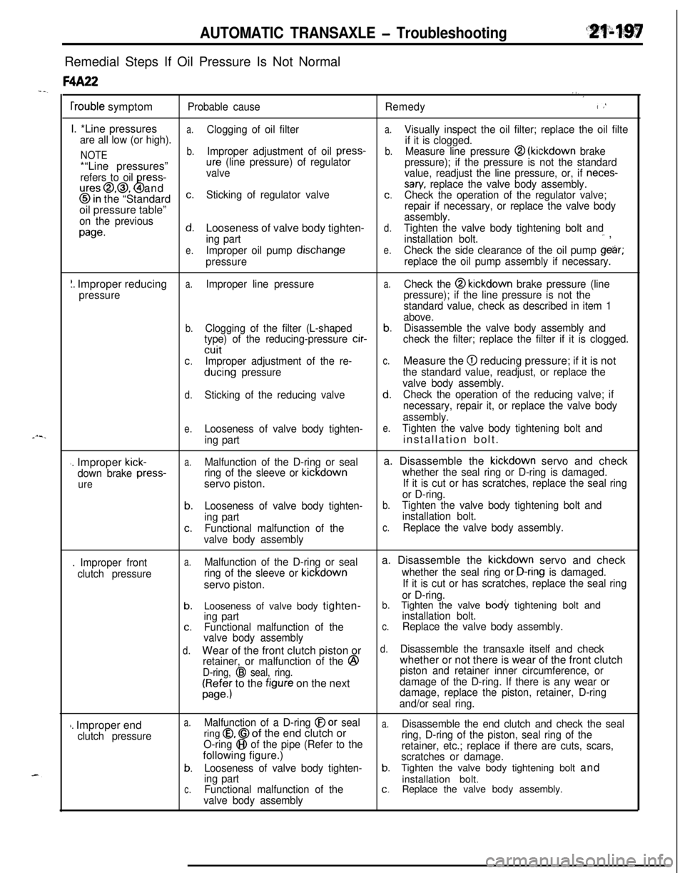
AUTOMATIC TRANSAXLE - TroubleshootingRemedial Steps If Oil Pressure Is Not Normal
F4A22.,,‘
frouble symptomProbable causeRemedy1;
I. *Line pressures
a.Clogging of oil filtera.Visually inspect the oil filter; replace the oil filte
are all low (or high).
if it is clogged.
NOTEb.Improper adjustment of oil press-b.Measure line pressure @ (kickdown brake*“Line pressures”ure (line pressure) of regulator
pressure); if the pressure is not the standard
refers to oil
ress-ures@,@, 4 and
8
valvevalue, readjust the line pressure, or, if neces-sary, replace the valve body assembly.
@in the “Standardc.Sticking of regulator valvec.Check the operation of the regulator valve;oil pressure table”repair if necessary, or replace the valve body
on the previousassembly.
page.d.Looseness of valve body tighten-d.Tighten the valve body tightening bolt and
ing partinstallation bolt.‘- ,
e.Improper oil pump dischangee.Check the side clearance of the oil pump gehr;
pressurereplace the oil pump assembly if necessary.
I. Improper reducinga.Improper line pressurea.Check the @ kickdown brake pressure (line
pressurepressure); if the line pressure is not the
standard value, check as described in item 1
above.
b.Clogging of the filter (L-shapedb.Disassemble the valve body assembly and
type) of the reducing-pressure cir-check the filter; replace the filter if it is clogged.cuit
c.Improper adjustment of the re-c.Measure the @I reducing pressure; if it is not
ducing pressurethe standard value, readjust, or replace the
valve body assembly.
d.Sticking of the reducing valved.Check the operation of the reducing valve; if
necessary, repair it, or replace the valve body
assembly.
e.Looseness of valve body tighten-e.Tighten the valve body tightening bolt and
ing partinstallation bolt.
#. Improper kick-a.Malfunction of the D-ring or seala. Disassemble the kickdown servo and check
down brake press-ring of the sleeve or kickdownwhether the seal ring or D-ring is damaged.
ureservo piston.If it is cut or has scratches, replace the seal ring
or D-ring.
b.Looseness of valve body tighten-b.Tighten the valve body tightening bolt and
ing partinstallation bolt.
c.Functional malfunction of thec.Replace the valve body assembly.
valve body assembly
. Improper front
clutch pressure
a.Malfunction of the D-ring or seala. Disassemble the kickdown servo and check
ring of the sleeve or kickdownwhether the seal ring or-D-ring is damaged.servo piston.
If it is cut or has scratches, replace the seal ring
or D-ring.
b.Looseness of valve body tighten-b.Tighten the valve body tightening bolt and
ing partinstallation bolt.c.Functional malfunction of thec.Replace the valve body assembly.
valve body assembly
d.Wear of the front clutch piston ord.Disassemble the transaxle itself and check
retainer, or malfunction of the
@whether or not there is wear of the front clutch
D-ring, @ seal, ring.piston and retainer inner circumference, or
ra;;; to the figure on the nextdamage of the D-ring. If there is any wear or
damage, replace the piston, retainer, D-ring
and/or seal ring.
1. Improper endclutch pressure
a.Malfunction of a D-ring @or seala.Disassemble the end clutch and check the sealring 0, @of the end clutch or
O-ring @I of the pipe (Refer to thering, D-ring of the piston, seal ring of thefollowing figure.)retainer, etc.; replace if there are cuts, scars,
scratches or damage.
b.Looseness of valve body tighten-b.Tighten the valve body tightening bolt and
ing partinstallation bolt.c.Functional malfunction of thec.Replace the valve body assembly.
valve body assembly
Page 899 of 1216
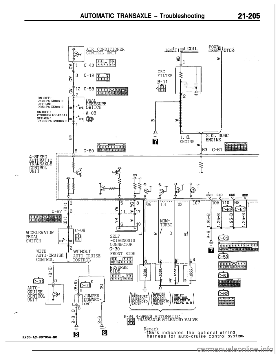
AUTOMATIC TRANSAXLE - Troubleshooting21-205
AIR CONDITIONER
CONTROL UNITIGNI
CRCFILTER
B-11
ON+OFF:2700kP.%(384Psl)OFF+ON:
$;X;kERATOR
SWITCH
WITH
WITHOUT,$J;$JR~;UISE 1AUTO-CRUISE. CONTROL
SELFJ-DIAGNOSIS
CONNECTOR
TIO1
/-1. 8LENGINE
3J
I
IL.&.j IUK1
mB
x 1
mm
CLCL
--
‘----_06
Pz
1_----
t
29I
POWE
TRANSTOR
c-30
FRONT SIDE
p&a-q
E%ERSE
p!!iQqI-----
101
NON-TURBC
/ 0
2_----II
A
-----02
9
I.----,
IL-B
GtD G:DGB“tD----1
B-24 4-SPEED AUTOMATICTRANSAXLE SOLENOID VALVE
Remark*%Mark indicates the optional wlrlnsharness for auto-cruise control system.KX35-AC-U0705A-NCfg