torque MITSUBISHI ECLIPSE 1991 User Guide
[x] Cancel search | Manufacturer: MITSUBISHI, Model Year: 1991, Model line: ECLIPSE, Model: MITSUBISHI ECLIPSE 1991Pages: 1216, PDF Size: 67.42 MB
Page 80 of 1216
2-32FRONT SUSPENSION - Strut Assemblv
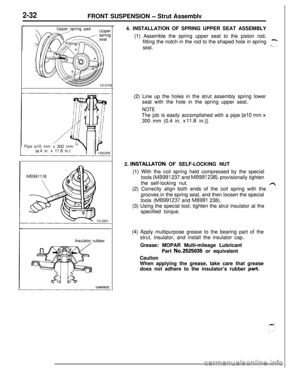
12LO251Insulator rubber12A0522,4. INSTALLATION OF SPRING UPPER SEAT ASSEMBLY
(1) Assemble the spring upper seat to the piston rod,
fitting the notch in the rod to the shaped hole in spring
-
seat.L .I(2) Line up the holes in the strut assembly spring lower
seat with the hole in the spring upper seat.
NOTEThe job is easily accomplished with a pipe
[ralO mm x300 mm (0.4 in.
x 11.8 in.)].
2.
INSTALLATON OF SELF-LOCKING NUT
(1) With the coil spring held compressed by the special
tools
(MB991 237 and MB991 238), provisionally tighten
the self-locking nut.
(2) Correctly align both ends of the coil spring with the
?grooves in the spring seat, and then loosen the special
tools (MB991237 and
MB991 238).
(3) Using the special tool, tighten the strut insulator at the
specified torque.
(4) Apply multipurpose grease to the bearing part of the
strut, insulator, and install the insulator cap.
Grease: MOPAR Multi-mileage Lubricant
Part No.2525035 or equivalent
Caution
When applying the grease, take care that grease
does not adhere to the insulator’s rubber
part.
Page 83 of 1216
FRONT SUSPENSION - Lower Arm2-35
12UOO18SERVICE POINTS OF REMOVAL
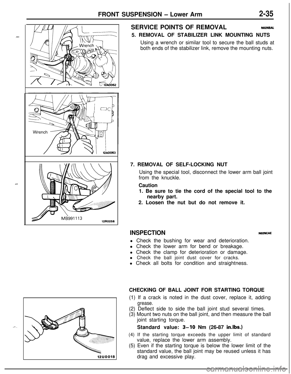
NOZNSAL5. REMOVAL OF STABILIZER LINK MOUNTING NUTS
Using a wrench or similar tool to secure the ball studs at
both ends of the stabilizer link, remove the mounting nuts.
7. REMOVAL OF SELF-LOCKING NUT
Using the special tool, disconnect the lower arm ball joint
from the knuckle.
Caution
1. Be sure to tie the cord of the special tool to the
nearby part.
2. Loosen the nut but do not remove it.
INSPECTIONNOZNCAEl Check the bushing for wear and deterioration.
l Check the lower arm for bend or breakage.
l Check the clamp for deterioration or damage.
l Check the ball joint dust cover for cracks.
l Check all bolts for condition and straightness.
CHECKING OF BALL JOINT FOR STARTING TORQUE
(1) If a crack is noted in the dust cover, replace it, adding
grease.(2) Deflect side to side the ball joint stud several times.
(3) Mount two nuts on the ball joint, and then measure the ball
joint starting torque.
Standard value:
3-10 Nm (26-87 in.lbs.)(4) If the starting torque exceeds the upper limit of standard
value, replace the lower arm assembly.
(5) Even if the starting torque is below the lower limit of the
standard value, the ball joint may be reused unless it has
drag and excessive play.
Page 88 of 1216
12LO244Z-40FRONT SUSPENSION - Stabilizer Bar
INSPECTIONNO2TCAFl Check the bushing for wear and deterioration.
l Check the stabilizer bar for deterioration or damage.
l Check the stabilizer link ball joint dust cover for cracks.
l Check all bolts for condition and straightness.
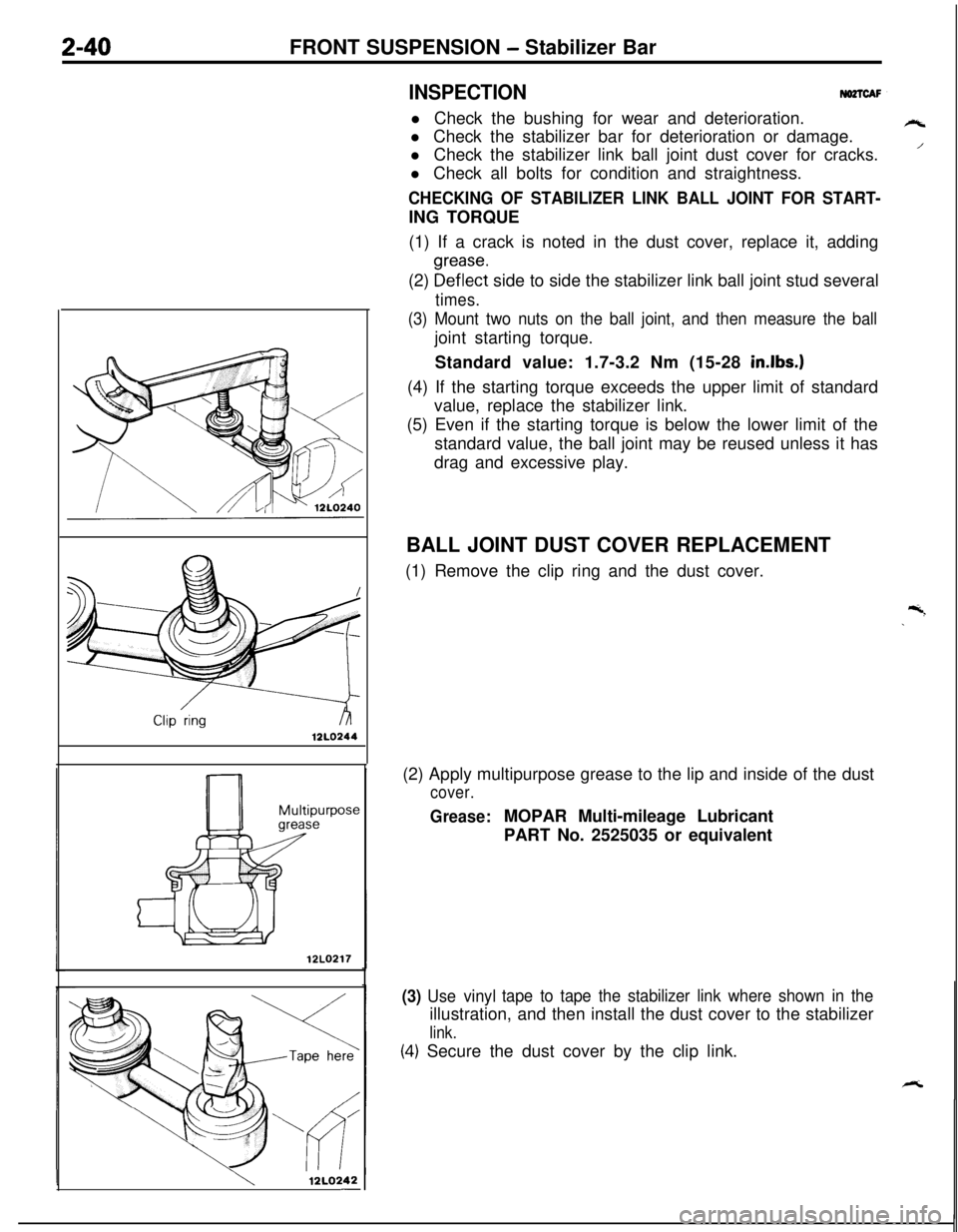
CHECKING OF STABILIZER LINK BALL JOINT FOR START-ING TORQUE
(1) If a crack is noted in the dust cover, replace it, adding
(2)
~~f~~~t side to side the stabilizer link ball joint stud several
times.
(3) Mount two nuts on the ball joint, and then measure the balljoint starting torque.
Standard value: 1.7-3.2 Nm (15-28
in.lbs.)(4) If the starting torque exceeds the upper limit of standard
value, replace the stabilizer link.
(5) Even if the starting torque is below the lower limit of the
standard value, the ball joint may be reused unless it has
drag and excessive play.
12LO217
12LQ242-BALL JOINT DUST COVER REPLACEMENT
(1) Remove the clip ring and the dust cover.
(2) Apply multipurpose grease to the lip and inside of the dust
cover.
Grease:MOPAR Multi-mileage Lubricant
PART No. 2525035 or equivalent
(3) Use vinyltape to tape the stabilizer link where shown in theillustration, and then install the dust cover to the stabilizer
link.
(4.) Secure the dust cover by the clip link.
rt
/
Page 103 of 1216
3-1
REAR AXLE
CONTENTSAXLE SHAFT
...................................................10
DIFFERENTIAL CARRIER................................19DRIVE SHAFT
..................................................13SERVICE ADJUSTMENT PROCEDURES..
.....8
GearOilLevelCheck...................................8
LimitedSlipDifferentialCheck....................9
..Rear Axle Total Backlash Check.................8Rear Wheel Bearing End Play Check
.........
8Rear Wheel Bearing Rotation Sliding
ResistanceCheck.........................................9
SPECIALTOOLS.............................................4
SPECIFICATIONS.............................................
2
GeneralSpecifications..................................2
Lubricants......................................................3Sealants and Adhesives...............................
3Service
Specifications...................................2TorqueSpecifications...................................
3
TROUBLESHOOTING......................................6Axle Shaft
Grease leakageNoise while wheels are rotatingDifferential (Conventional Differential)
Bearing noise while driving or coasting
Constant noise
Gear noise while coasting
Gear noise while driving
HeatNoise while turning
Oil leakage
Differential (Limited Slip Differential)
Abnormal noise during driving or
gear changing
Abnormal noise when cornering
Break down
Gear noise
Gear oil leakage
SeizureThe limited slip differential does
not function
Drive Shaft
Noise
Page 104 of 1216
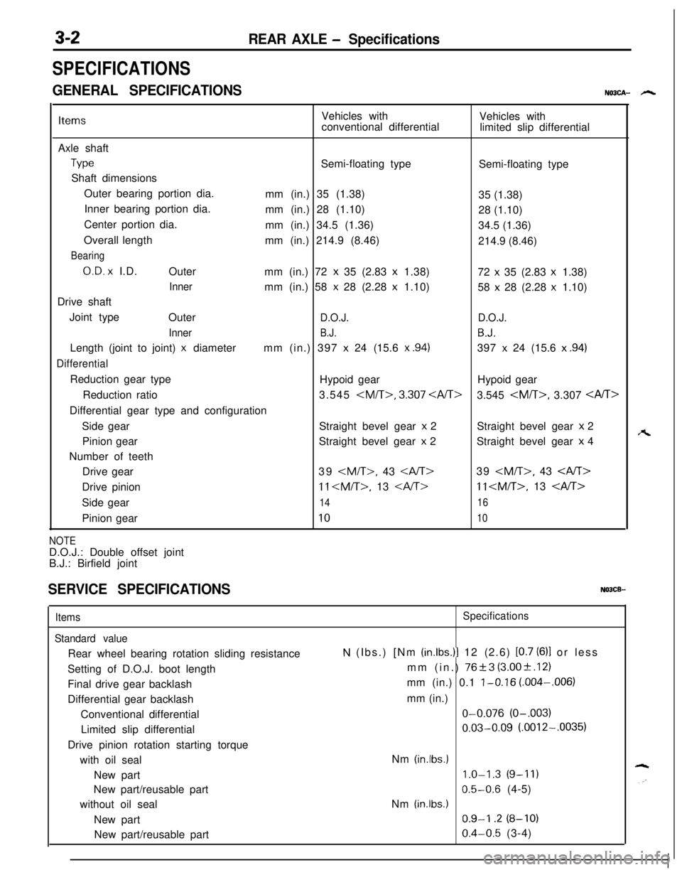
3-2REAR AXLE - Specifications
SPECIFICATIONS
GENERAL SPECIFICATIONSNO3CA- h
ItemsVehicles with
Vehicles with
conventional differential
limited slip differential
Axle shaft
TypeSemi-floating type
Semi-floating type
Shaft dimensions
Outer bearing portion dia.
mm (in.) 35 (1.38)
35 (1.38)
Inner bearing portion dia.
mm (in.) 28 (1.10)
28 (1.10)
Center portion dia.
mm (in.) 34.5 (1.36)
34.5 (1.36)
Overall length
mm (in.) 214.9 (8.46)
214.9 (8.46)
Bearing
O.D. x I.D.
Outer
mm (in.) 72 x 35 (2.83 x 1.38)
72 x 35 (2.83 x 1.38)
Innermm (in.) 58 x 28 (2.28 x 1.10)
58 x 28 (2.28 x 1.10)
Drive shaft
Joint type
Outer
D.O.J.D.O.J.
Inner
B.J.B.J.Length (joint to joint)
x diametermm (in.) 397 x 24 (15.6 x .94)397 x 24 (15.6 x .94)
DifferentialReduction gear type
Hypoid gearHypoid gear
Reduction ratio3.545
3.545
Side gearStraight bevel gear
x 2Straight bevel gear x 2
Pinion gearStraight bevel gear
x 2Straight bevel gear x 4
Number of teeth
Drive gear39
11
Side gear
1416Pinion gear
1010
NOTED.O.J.: Double offset joint
B.J.: Birfield joint
SERVICE SPECIFICATIONSNOBCB-
Items
Standard valueRear wheel bearing rotation sliding resistance
Setting of D.O.J. boot length
Final drive gear backlash
Differential gear backlash
Conventional differential
Limited slip differential
Drive pinion rotation starting torque
with oil seal
New part
New part/reusable part
without oil seal
New part
New part/reusable partSpecifications
N (Ibs.) [Nm (in.lbs.)l 12 (2.6) [0.7 (6)l or less
mm (in.)
76+3 (3.00+.12)
mm (in.) 0.1
l-0.16 (.004-,006)
mm (in.)O-0.076
(O-.003)
0.03-0.09 (.0012-.0035)
Nm
(in.lbs.)
1.0-1.3 (9-11)
0.5-0.6 (4-5)
Nm
(in.lbs.)
0.9-I .2 (8-10)
0.4-0.5 (3-4)
A
Page 105 of 1216
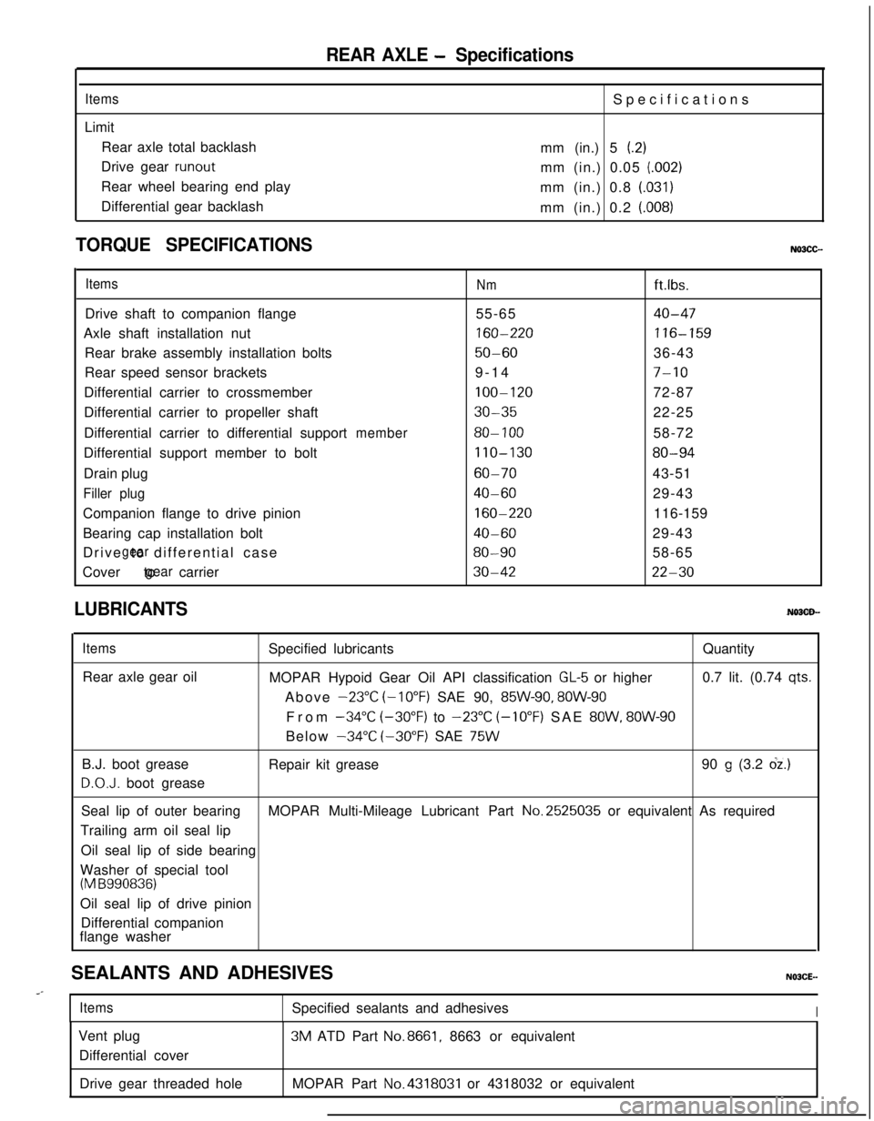
REAR AXLE - Specifications
ItemsLimit
Rear axle total backlash
Drive gear
runoutRear wheel bearing end play
Differential gear backlashSpecifications
mm (in.) 5
(.2)mm (in.) 0.05
(.002)mm (in.) 0.8
(.031)mm (in.) 0.2
(.008)
TORQUE SPECIFICATIONS
ItemsNmft.lbs.
Drive shaft to companion flange55-65
40-47Axle shaft installation nut
160-220116-159Rear brake assembly installation bolts
50-6036-43
Rear speed sensor brackets9-14
7-10Differential carrier to crossmember
100-12072-87
Differential carrier to propeller shaft
30-3522-25
Differential carrier to differential support
member80- 10058-72
Differential support member to bolt
110-13080-94Drain plug
60-7043-51
Filler plug40-6029-43
Companion flange to drive pinion
160-220116-159
Bearing cap installation bolt
40-6029-43
Drive to differential case
gear80-9058-65
Cover to carrier
gear30-4222-30
LUBRICANTS
ItemsRear axle gear oilSpecified lubricantsQuantity
MOPAR Hypoid Gear Oil API classification
GL-5 or higher0.7 lit. (0.74 qts.Above
-23°C (-10°F) SAE 90, 85W-90, 8OW-90From
-34°C (-30°F) to -23°C (-10°F) SAE 8OW, 8OW-90Below
-34°C (-30°F) SAE 75WB.J. boot grease
D.O.J. boot greaseRepair kit grease90
g (3.2 dz.)Seal lip of outer bearingMOPAR Multi-Mileage Lubricant Part No.2525035 or equivalent As required
Trailing arm oil seal lip
Oil seal lip of side bearing
Washer of special tool
(M B990836)Oil seal lip of drive pinion
Differential companion
flange washer
SEALANTS AND ADHESIVES
..-
ItemsSpecified sealants and adhesivesIVent plug
Differential cover3M ATD Part
No.8661, 8663 or equivalent
Drive gear threaded holeMOPAR Part
No.4318031 or 4318032 or equivalent
Page 106 of 1216

REAR AXLE - SDecial Tools
SPECIAL TOOLSN03DA--
ToolNumber
Name
UseMB990767
End yoke holderMeasurement of rotation torque of the limiter
/slip differentialStop axle shaft turning
CT-l 003Axle shaft pullerPress-fitting the drive pinion rear bearing outerace
Sliding hammer set
Removal of the axle shaftMB990560
Bearing removerRemoval of the axle shaft dust cover, oute
bearing and rear rotor
Press-in the outer wheel bearing and rear rotorMB991115
Oil seal installer
Press-fitting of drive shaft oil seal
Side bearing puller
Removal of the side
Page 110 of 1216
3-8REAR AXLE - Service Adjustment Procedures
09D031
llA0065SERVICE ADJUSTMENT PROCEDURES
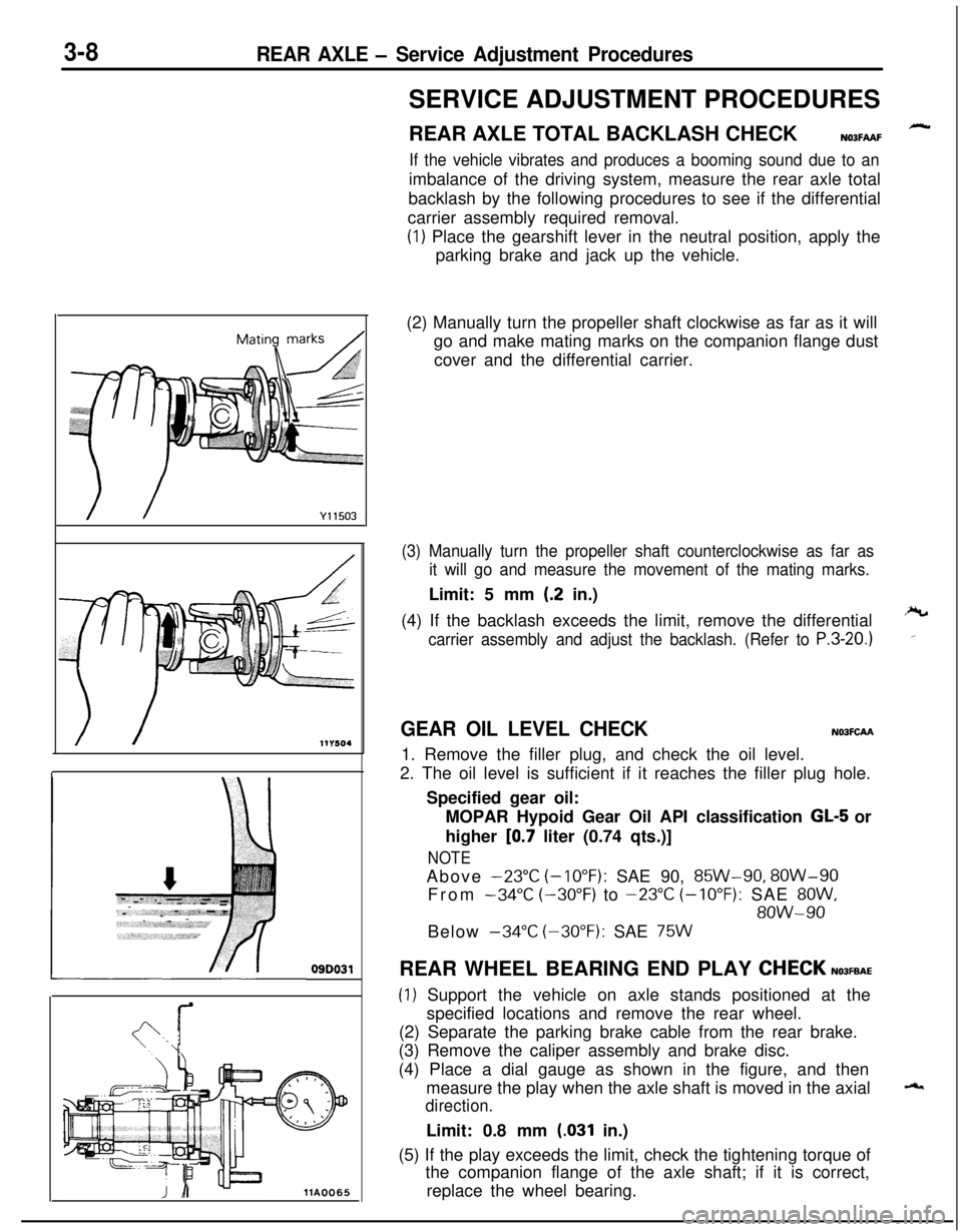
REAR AXLE TOTAL BACKLASH CHECK
N03FAAF
If the vehicle vibrates and produces a booming sound due to animbalance of the driving system, measure the rear axle total
backlash by the following procedures to see if the differential
carrier assembly required removal.
(1) Place the gearshift lever in the neutral position, apply the
parking brake and jack up the vehicle.
(2) Manually turn the propeller shaft clockwise as far as it will
go and make mating marks on the companion flange dust
cover and the differential carrier.
(3) Manually turn the propeller shaft counterclockwise as far as
it will go and measure the movement of the mating marks.Limit: 5 mm
(.2 in.)
(4) If the backlash exceeds the limit, remove the differential
carrier assembly and adjust the backlash. (Refer to P.3-20.)
GEAR OIL LEVEL CHECKN03FCAA1. Remove the filler plug, and check the oil level.
2. The oil level is sufficient if it reaches the filler plug hole.
Specified gear oil:
MOPAR Hypoid Gear Oil API classification
GL-5 or
higher
[0.7 liter (0.74 qts.)]
NOTEAbove
-23°C (-10°F): SAE 90, 85W-90, 8OW-90
From
-34°C (-30°F) to -23°C (-10°F): SAE 8OW,
8OW-90Below
-34°C (-30°F): SAE 75WREAR WHEEL BEARING END PLAY
CHECKN03FEAE
(1) Support the vehicle on axle stands positioned at the
specified locations and remove the rear wheel.
(2) Separate the parking brake cable from the rear brake.
(3) Remove the caliper assembly and brake disc.
(4) Place a dial gauge as shown in the figure, and then
measure the play when the axle shaft is moved in the axial
direction.Limit: 0.8 mm
(.031 in.)
(5) If the play exceeds the limit, check the tightening torque of
the companion flange of the axle shaft; if it is correct,
replace the wheel bearing.
Page 111 of 1216
REAR AXLE - Service Adjustment Procedures3-9
14A0521
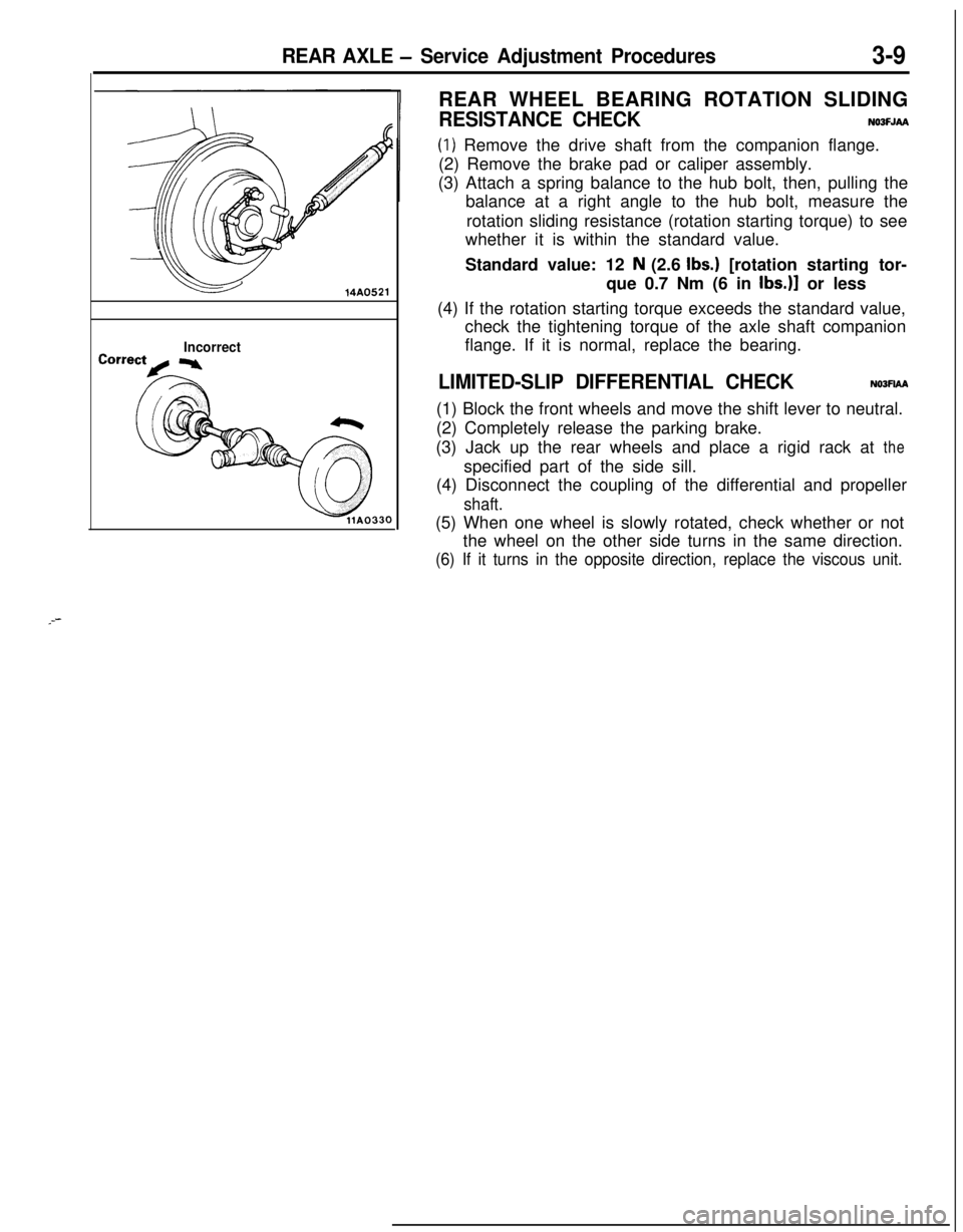
IncorrectREAR WHEEL BEARING ROTATION SLIDING
RESISTANCE CHECKNOOFJAA
(1) Remove the drive shaft from the companion flange.
(2) Remove the brake pad or caliper assembly.
(3) Attach a spring balance to the hub bolt, then, pulling the
balance at a right angle to the hub bolt, measure the
rotation sliding resistance (rotation starting torque) to see
whether it is within the standard value.
Standard value: 12
N (2.6 Ibs.) [rotation starting tor-
que 0.7 Nm (6 in
Ibs.)] or less
(4) If the rotation starting torque exceeds the standard value,
check the tightening torque of the axle shaft companion
flange. If it is normal, replace the bearing.
LIMITED-SLIP DIFFERENTIAL CHECKNOJFIAA(1) Block the front wheels and move the shift lever to neutral.
(2) Completely release the parking brake.
(3) Jack up the rear wheels and place a rigid rack at the
specified part of the side sill.
(4) Disconnect the coupling of the differential and propeller
shaft.(5) When one wheel is slowly rotated, check whether or not
the wheel on the other side turns in the same direction.
(6) If it turns in the opposite direction, replace the viscous unit.
_--
Page 117 of 1216
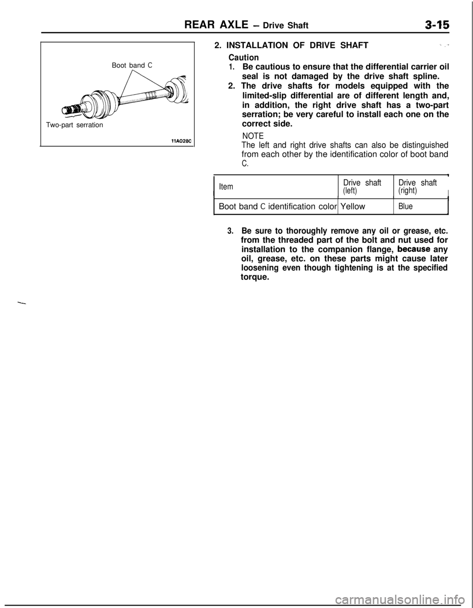
REAR AXLE - Drive Shaft
Boot band
CTwo-part serration
llA02802. INSTALLATION OF DRIVE SHAFT
I_ ,T
Caution
1.Be cautious to ensure that the differential carrier oil
seal is not damaged by the drive shaft spline.
2. The drive shafts for models equipped with the
limited-slip differential are of different length and,
in addition, the right drive shaft has a two-part
serration; be very careful to install each one on the
correct side.
NOTE
The left and right drive shafts can also be distinguishedfrom each other by the identification color of boot band
C.
IItemDrive shaftDrive shaft
(left)(right)IIIBoot band
C identification color YellowBlueI
3.Be sure to thoroughly remove any oil or grease, etc.from the threaded part of the bolt and nut used for
installation to the companion flange,
because any
oil, grease, etc. on these parts might cause later
loosening even though tightening is at the specifiedtorque.