wheel alignment MITSUBISHI ECLIPSE 1991 User Guide
[x] Cancel search | Manufacturer: MITSUBISHI, Model Year: 1991, Model line: ECLIPSE, Model: MITSUBISHI ECLIPSE 1991Pages: 1216, PDF Size: 67.42 MB
Page 613 of 1216
Special Tools/Troubleshooting/REAR SUSPENSION
SPECIAL TOOLN17DA.A
ToolNumberName1 Use1
L-451 4
Spring compressorRemoval and installation of the coil spring
bodyTROUBLESHOOTINGNI’IEA-A
Symptom
Squeaks or other
abnormal noiseProbable cause
Loose rear suspension installation bolts and nuts
Malfunction of shock absorber
Worn bushings
Remedy
Retighten
Replace
Poor rideExcessive tire inflation pressure
Malfunction of shock absorberWeak or broken springs
Adjust the pressure
Replace
Body tiltingWeak or deteriorated bushings
Weak or broken springs
Replace
SERVICE ADJUSTMENT PROCEDURES
REAR WHEEL ALIGNMENT INSPECTIONN17FAAC
The rear suspension assembly must be free of worn, loosen or
damaged parts prior to measurement of rear wheel alignment.
Standard value:
Toe-in (Left-right difference)
Of3 mm (Of.118 in.)
Camber-45’ + 30’
NOTEThe rear wheel alignment is set at the factory and cannot be
adjusted.If toe-in or camber is not within the standard value, replace
bent or damaged parts.
WHEEL BEARING END PLAY ADJUSTMENT,7FBA0
1.Inspect the play of the bearings while the vehicle is jacked
up and resting on floor jack.
2.Remove the hub cap and then release the parking brake.
3. Remove the caliper assembly and the brake disc.
4. Check the bearing’s end play.
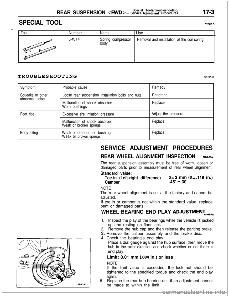
Place a dial gauge against the hub surface; then move the
hub in the axial direction and check whether or not there isend play.
Limit: 0.01 mm
(.004 in.) or less
NOTE12AO531If the limit value is exceeded, the lock nut should be
tightened to the specified torque and check the end play
again.
5.Replace the rear hub bearing unit if an adjustment cannot
be made to within the limit.
Page 630 of 1216
17-20REAR SUSPENSION
12R0556-- Upper arm
(L.H.)
12A0081
SERVICE ADJUSTMENT PROCEDURES
REAR WHEEL ALIGNMENT INSPECTIONN17FDAB is.Measure the wheel alignment with the vehicle parked on level
--’
ground.The rear suspension and wheels should be inspected for
wear’or damage and repaired prior to measurement of wheel,
alignment.
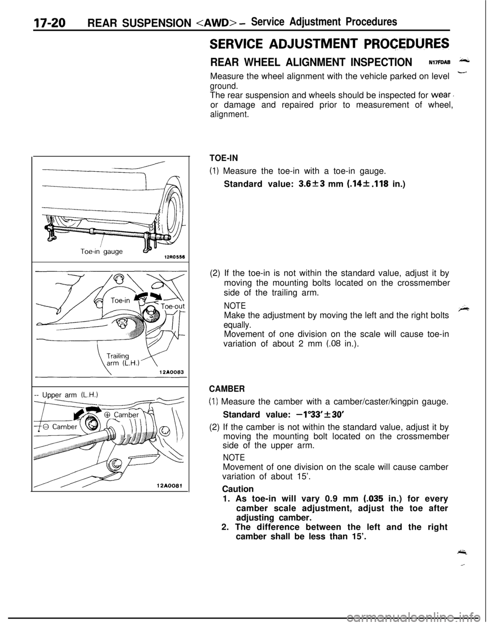
TOE-IN
(1) Measure the toe-in with a toe-in gauge.
Standard value:
3.6f3 mm (.14+ .I18 in.)
(2) If the toe-in is not within the standard value, adjust it by
moving the mounting bolts located on the crossmember
side of the trailing arm.
NOTEMake the adjustment by moving the left and the right bolts
r;hr
equally.Movement of one division on the scale will cause toe-in
variation of about 2 mm
(.08 in.).
CAMBER
(1) Measure the camber with a camber/caster/kingpin gauge.
Standard value:
-1”33’f30’(2) If the camber is not within the standard value, adjust it by
moving the mounting bolt located on the crossmember
side of the upper arm.
NOTEMovement of one division on the scale will cause camber
variation of about 15’.
Caution
1. As toe-in will vary 0.9 mm
(.035 in.) for every
camber scale adjustment, adjust the toe after
adjusting camber.
2. The difference between the left and the right
camber shall be less than 15’.
Page 631 of 1216
REAR SUSPENSION
REAR SUSPENSION ASSEMBLY
5.REMOVAL AND INSTALLATIONN17GA-BPost-installation Operation
l Check of Wheel Alignment(Refer to P.17-20.)@Check of ParkingBrakeLever Stroke
(Refer to GROUP 5-Service Adjust
ment Procedures.)
l installation of Hole Cover(Refer to GROUP 23-Trims.)9-14 Nm
7-10 ft.lbs.
/
12AO640
\lo-15 Nm7-l 1 ft.lbs.
30-40 Nm
22-29 ft.lbs.
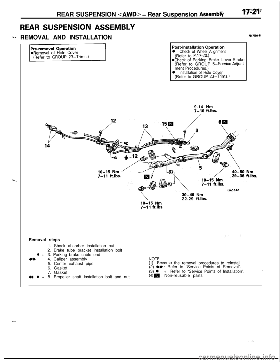
Removal steps
1. Shock absorber installation nut
2. Brake tube bracket installation bolt
l +3. Parking brake cable end
**4. Caliper assembly
5. Center exhaust pipe!rEeverse the removal procedures to reinstall.
6. Gasket(2) 4e: Refer to “Service Points of Removal”.
7. Gasket(3) l + : Refer to “Service Points of Installation”.’+I)
l +8. Propeller shaft installation bolt and nut(4) m : Non-reusable parts
Page 638 of 1216
17-28REAR SUSPENSION
TRAILING ARMr
{EMOVAL AND INSTALLATION
9-14 Nm7-10 ft.lbs.
\SO-110
Nm50-60 Nm36-43 ft.lbs. !65-80 ftlbs.
/160-220 Nm\\\ /zdnnecting
/
/
13
_-_ --- .~~~~116-159 ftlbs.55-65
Nm40-47 ft.lbs.5m
60-72 Nrn43-52 ft.lbs.
/-\
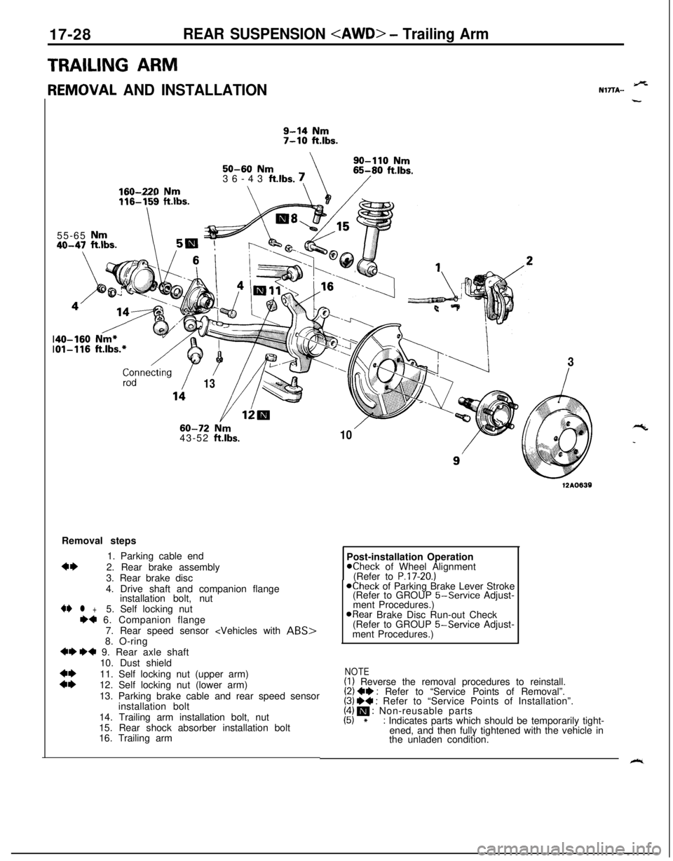
103Removal steps
1. Parking cable end
4*2. Rear brake assembly
3. Rear brake disc
4. Drive shaft and companion flange
installation bolt, nut4I)
l +5. Self locking nut++ 6. Companion flange
7. Rear speed sensor
+I) ++ 9. Rear axle shaft
10. Dust shield
::11. Self locking nut (upper arm)
12. Self locking nut (lower arm)
13. Parking brake cable and rear speed sensor
installation bolt
14. Trailing arm installation bolt, nut
15. Rear shock absorber installation bolt
16. Trailing arm
12A0639Post-installation Operation
Kheck of Wheel Alignment
(Refer to P.17-20.)@Check of Parking Brake Lever Stroke
(Refer to GROUP 5-Service Adjust-
ment Procedures.)
@Rear Brake Disc Run-out Check
(Refer to GROUP 5-Service Adjust-
ment Procedures.)
NOTE(I) Reverse the removal procedures to reinstall.(2) ++ : Refer to “Service Points of Removal”.(3) W : Refer to “Service Points of Installation”.(4) m : Non-reusable parts(5) *: Indicates parts which should be temporarily tight-
ened, and then fully tightened with the vehicle in
the unladen condition.
9%NlTTA-
“c
_
k.
Page 668 of 1216
19-20STEERING - Steering Wheel and Shaft
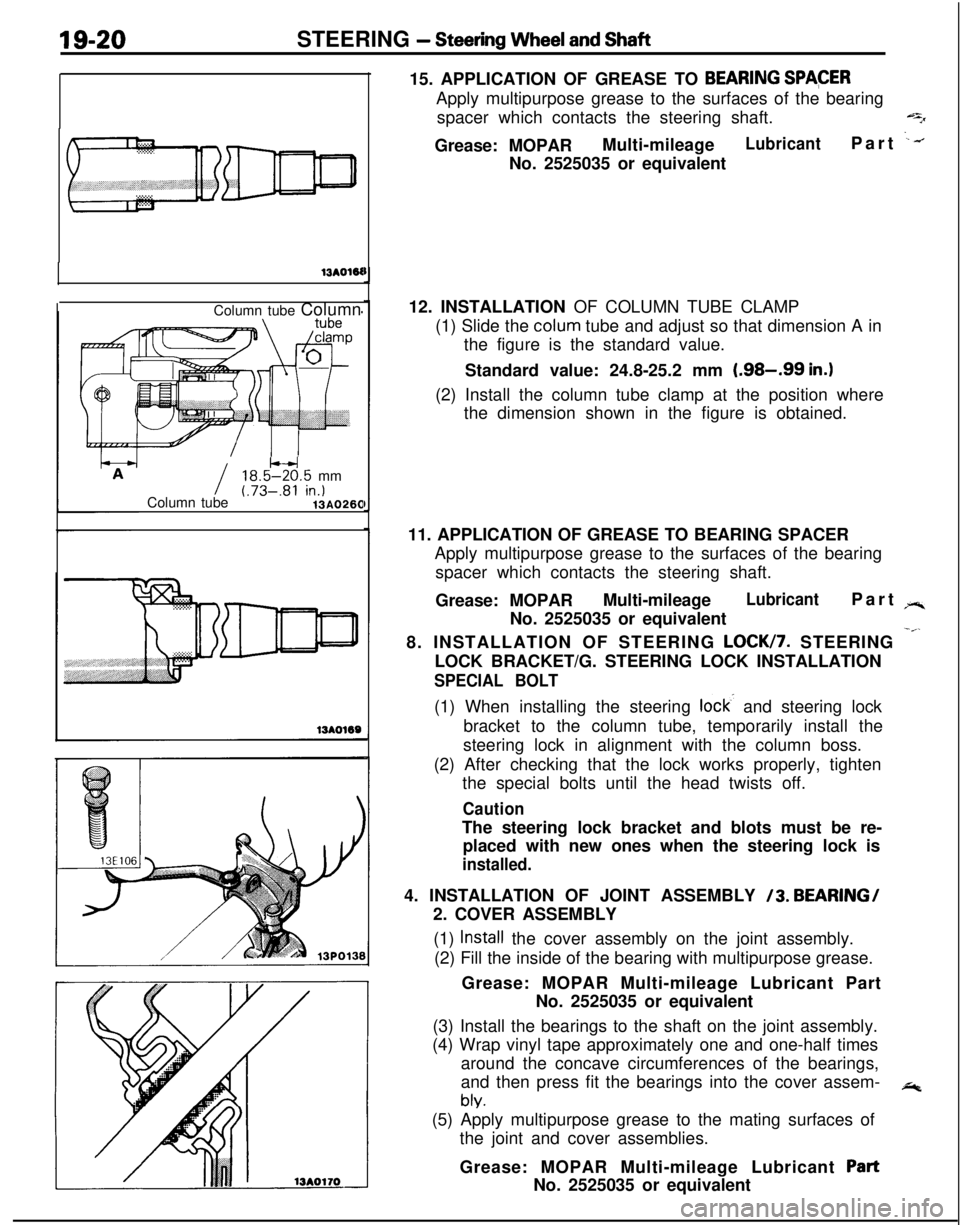
13AOWColumn tube Column
I18.5W.5 mm
Column tube(.73-.81 in.)13AO26015. APPLICATION OF GREASE TO
BEARING SPACERApply multipurpose grease to the surfaces of the bearing
spacer which contacts the steering shaft.
qGrease: MOPARMulti-mileage
LubricantPart .--.No. 2525035 or equivalent
12. INSTALLATION OF COLUMN TUBE CLAMP
(1) Slide the colum tube and adjust so that dimension A in
the figure is the standard value.
Standard value: 24.8-25.2 mm
(.98-.99 in.)(2) Install the column tube clamp at the position where
the dimension shown in the figure is obtained.
11. APPLICATION OF GREASE TO BEARING SPACER
Apply multipurpose grease to the surfaces of the bearing
spacer which contacts the steering shaft.
Grease: MOPARMulti-mileage
LubricantPart rr.No. 2525035 or equivalent
8. INSTALLATION OF STEERING
LOCK/7. STEERING -”LOCK BRACKET/G. STEERING LOCK INSTALLATION
SPECIAL BOLT(1) When installing the steering
lock- and steering lock
bracket to the column tube, temporarily install the
steering lock in alignment with the column boss.
(2) After checking that the lock works properly, tighten
the special bolts until the head twists off.
CautionThe steering lock bracket and blots must be re-
placed with new ones when the steering lock is
installed.4. INSTALLATION OF JOINT ASSEMBLY
/3. BEARING/
2. COVER ASSEMBLY
(1)
Install the cover assembly on the joint assembly.
(2) Fill the inside of the bearing with multipurpose grease.
Grease: MOPAR Multi-mileage Lubricant Part
No. 2525035 or equivalent
(3) Install the bearings to the shaft on the joint assembly.
(4) Wrap vinyl tape approximately one and one-half times
around the concave circumferences of the bearings,
and then press fit the bearings into the cover assem-
*
bly.(5) Apply multipurpose grease to the mating surfaces of
the joint and cover assemblies.
Grease: MOPAR Multi-mileage Lubricant
PartNo. 2525035 or equivalent
Page 676 of 1216
19-28STEERING - Power Steering Gear Box
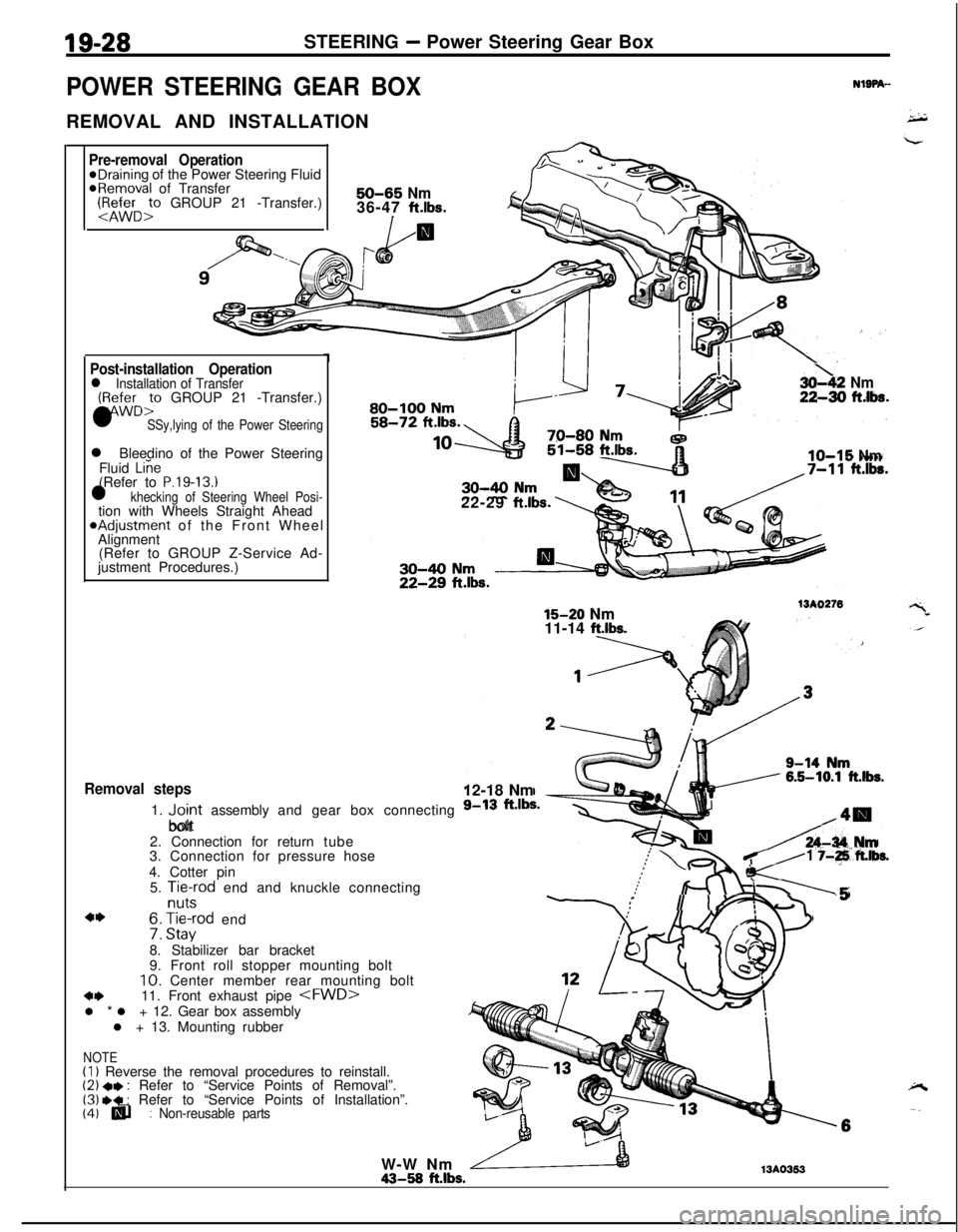
POWER STEERING GEAR BOXREMOVAL AND INSTALLATION
-
NlSPA--
Pre-removal Operation@Draining of the Power Steering Fluid@Removal of Transfer:1&&r:, GROUP 21 -Transfer.)50-65 Nm36-47 ft.lbs.
I/a
Post-installation Operationl Installation of Transfer(:zD:” GROUP 21 -Transfer.)
l SSy,lying of the Power Steeringl Bleedino of the Power Steering
Fluid
Liie(Refer to P.19-13.1l khecking of Steering Wheel Posi-tion with Wheels Straight Ahead*Adjustment of the Front Wheel
Alignment
(Refer to GROUP Z-Service Ad-
justment Procedures.)
Removal steps1.
“,;;rt assembly and gear box connecting
bolt
2. Connection for return tube
3. Connection for pressure hose
4. Cotter pin
5.
Aft-cd end and knuckle connecting
4I)f3: H,“a:od end
8. Stabilizer bar bracket
9. Front roll stopper mounting bolt10. Center member rear mounting bolt
4411. Front exhaust pipe
l + 13. Mounting rubber
(I) Reverse the removal procedures to reinstall.(2) +e : Refer to “Service Points of Removal”.(3) .* : Refer to “Service Points of Installation”.(4) q : Non-reusable parts(4) lli
3oh2 Nm22-30 ftlba.^a-aa I.au-IUU NrnI
IO-15 Nm22-29
ft.lbs.
15-20 Nm15-20 Nm
11-14 ft.lbs.
13A027612-18 Nm
A-34 IUm
K-
1 j-+ft.lbs.
:II I-.5
/ .2!
i!!1
NOTEW-W Nm43-58
ft.lbs.13A0353
Page 1041 of 1216
WHEELS AND TIRES - Troubleshooting22-3
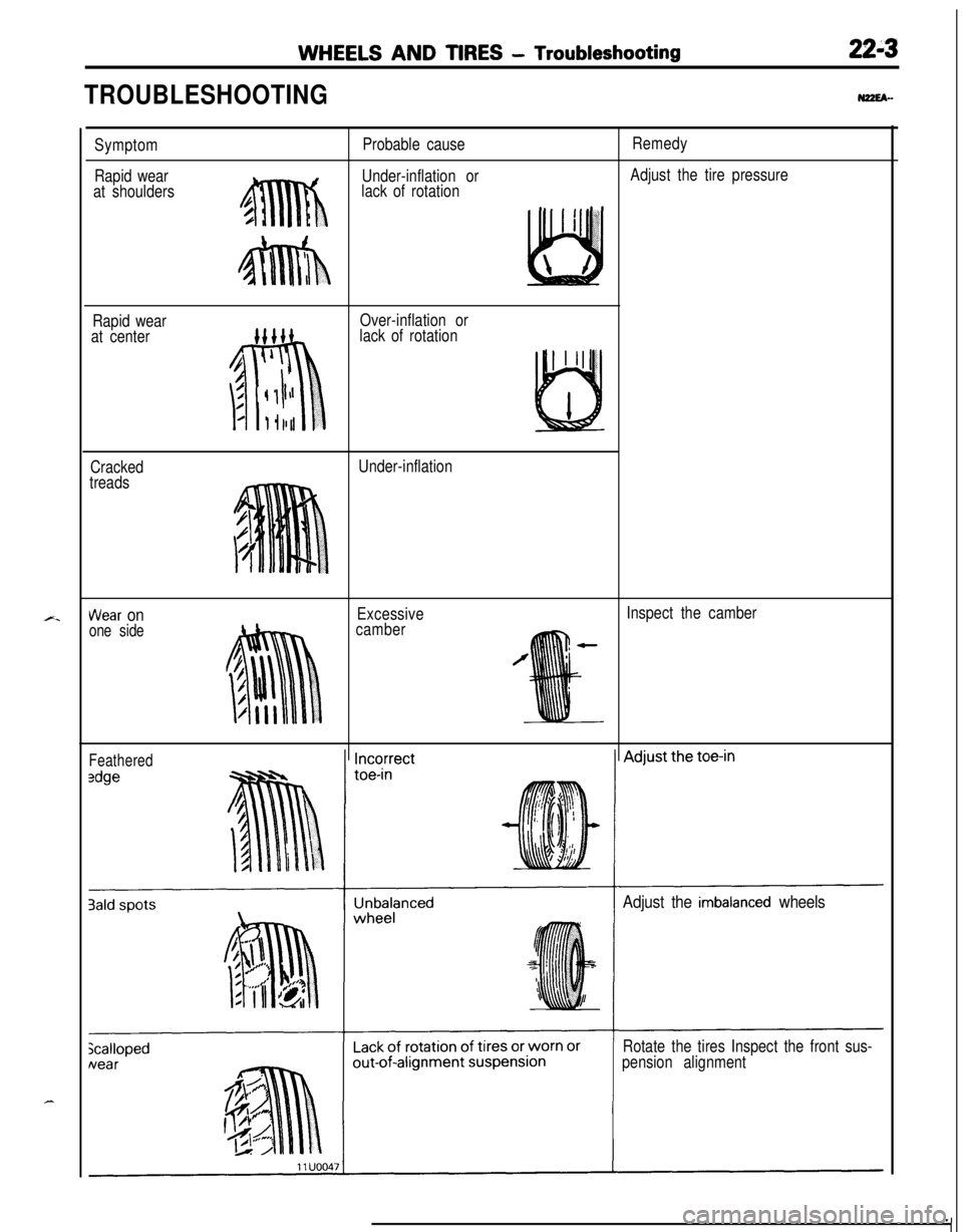
TROUBLESHOOTINGN22EA-
Symptom
Rapid wear
at shouldersProbable cause
Under-inflation or
lack of rotationRemedy
Adjust the tire pressure
Rapid wear
at centerOver-inflation or
lack of rotation
Cracked
treadsUnder-inflation
Wear onone side
Excessive
camberInspect the camber
Feathered
Adjust the imbalanced wheels
Rotate the tires Inspect the front sus-
pension alignment